Routers and switches need to use optical modules and fiber patch cord to realize the interconnection between network devices. Usually, Gigabit switch can be matched with gigabit optical module and 10 Gigabit optical module. Optical switching represents a fundamental technological evolution, shifting data routing from the domain of electrons to the realm of photons, or light. This transition allows data to remain in its native optical form as it travels through fiber optic networks, eliminating the need for. Optical switches are devices that route light signals from one path to another without converting them into electrical signals first. They're a core component in fiber-optic networks, where data travels as pulses of light through glass fibers. Every time that light needs to change direction or jump. An SFP (Small Form-factor Pluggable) module is a hot-swappable transceiver used in switches, routers, servers, and telecom equipment to transmit data over fiber or copper connections. Different SFP modules support different: That's why selecting the correct model matters. Think of it as the “translator” for your network equipment, converting electrical signals into optical signals. Switch optical modules, which convert electrical signals to optical signals and vice – versa, and optical interfaces, which serve as the physical connection points, play a pivotal role in determining the speed, distance, and reliability of data transmission.
[PDF]
Various optically switched architecture prototypes, based on the above optical switches, have been proposed to demonstrate the potential of optical data center networks. Optical data center networks are mainl.
[PDF]
Variety of applications and services depend on data centers to provide the high reliability and availability of computing and storage resource at minimal costs. Along with the emerging of traffic boosting applic.
[PDF]
This Technical Brochure describes the induction phenomena (inductive, capacitive and conductive) that can lead to presence of voltage and currents on disconnected cable systems. The optical fiber composite overhead ground wire (OPGW) has been widely used in power transmission lines. Methods of calculation to evaluate those values and touch voltages are detailed and analysed, associated with various. working on cables u al, photocopying, recording or otherwise, without the prior written or use by members of the Energy Networks Association to take account of the conditions which apply to them. Advice should. Literature review: An in-depth literature review covering the modelling and calculations of the conditions relating to faults caused by interactions between fibre optic cables and power cores in submarine cables. Examples of electrically conductive installations where induced voltage may occur could be: • Overhead lines or cables out of opera- tion •.
[PDF]
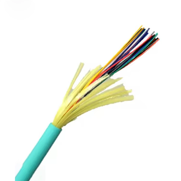
Fiber optic "cable" refers to the complete assembly of fibers, other internal parts like buffer tubes, ripcords, stiffeners, strength members all included inside an outer protective covering called the jacket. Cable provides protection for the optical fiber or fibers within it appropriate for the environment in which it is installed. You will also learn how different aspects of the product can affect budget and design. ■ The Five Key Parts of a Fiber Optic Cable A fiber optic cable. A fiber optic cable consists of five basic components: the core, the cladding, the coating, the strengthening fibers, and the cable jacket. When searching for a fiber optic cable, we need to pay attention not only to the connectors, such as SC to ST fiber cable, LC to SC fiber patch cable, or SC to. A TOSLINK optical fiber cable with a clear jacket. These cables are used mainly for digital audio connections between devices. This advanced cabling solution allows fast, secure data transfer and telecom over long distances. Understanding the components within a fiber optic cable enables. While fiber optic cable itself is cheaper than an equivalent length of copper cable, fiber optic cable connectors and the equipment needed to install them have typically been more expensive than their copper counterparts.
[PDF]
In this Cisco Tech Talk, learn how to view the optical module status on a Cisco switch using the Command Line Interface (CLI). This video demonstrates how to access the optical module status, check for any issues, and monitor the health of your network's optical components. Learn. When optical modules operate on a switch, it is usually necessary to read the module's internal information to understand its working status—such as connection status and real-time metrics like optical power and temperature. Additionally, identifying module information helps detect coding. This chapter describes how to configure the Optical Amplifier Module and Protection Switching Module (PSM). When you plan to replace a configured optical module with a different type of optical module, you must clear the configurations of the old module before you install the new module. By checking module health, compatibility, and digital diagnostics, you can quickly confirm correct installation, detect optical problems, and maintain accurate hardware. Small Form-factor Pluggable modules (SFP module) are the workhorses of modern network connectivity, enabling flexible fiber optic or copper links between switches, routers, firewalls, and servers. Whether you're upgrading bandwidth, replacing a faulty unit, or reconfiguring your topology, knowing.
[PDF]
This paper aims to study the design, simulation, and optimization of low-loss Y-branch passive optical splitters up to 64 output ports for telecommunication applications. For a waveguide channel profile, the standard material silica-on-silicon is used. Two important technologies for optical layer monitoring are Optical Performance Monitoring (OPM) and Optical Power Detection (OPD). Although they aim to maintain network health, they differ significantly in scope, technique, and deployment. This article delves into these differences, equipping. Optical Performance Monitoring (OPM) is considered a necessity over an optical network to enable sensibility of traffic line status and attain outstanding Quality-of-Service (QoS). The Y-splitters are designed and simulated at. Passive optical networks (PONs) are the network architecture of choice for residential fiber deployments. A PON is designed specifically to be cost-effective for delivering high data-rates to large customer populations. signals and various components of OPM functionalities are indispensable robust network operation and plays a key role flexibility and improve overall. Optical performance monitoring (OPM) is used for managing high capacity dense wavelength-division multiplexing (DWDM) optical transmission and switching systems in Next Generation Networks (NGN). OPM involves assessing the quality of data channel by measuring its optical characteristics without.
[PDF]
Optical trap or "tweezers" is a device used to apply piconewton sized forces and make precise measurements on a scale of roughly one micron. It can be created by applying a precisely focused laser onto a dielectric material. Thorlabs' OTKB (/M) Modular Optical Tweezers provide users with a tool for trapping and manipulating microscopic-sized objects. These laser-based tweezers, or traps, have been employed in numerous biological experiments. Biological applications for optical tweezers include trapping viruses and. Our advanced optical trap generator based on ultra-fast AOD technology. Versatile and flexible optical trap manipulation designed for biological samples. Learn to calibrate the 20. Use calibration information to observe the rotation of E. coli bacteria, and determine the forces required to stop this rotation. Based on their design, Thorlabs has collaborated with the aforementioned authors to design an OTKB optical trapping kit that includes all necessary components and provides the same capabilities. Enclosed into a high-quality aluminum box and assembled onto the. Torr Scientific offers a range of magneto-optical traps (MOT) (also known as atom trap chambers) used as part of ultra-cold vacuum systems, to capture atoms for testing purposes. This is a chamber module, formed of low-magnetic permeability materials for use at ultra-low temperatures nearing.
[PDF]
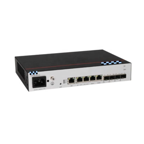
The SFP optical module is a standardized, modular assembly designed to be quickly installed or removed from a device's port without requiring the device to be powered down. This key feature—being hot-pluggable —is essential for simplifying network maintenance and minimizing downtime. SFP (Small Form-factor Pluggable) is a compact, hot-pluggable network interface module used to connect network devices (switches, routers, firewalls) to fiber optic or copper cables. It converts electrical signals into optical (or copper) signals and vice versa. An SFP transceiver acts as a compact, hot-swappable optical transceiver that. An SFP switch uses Small Form-Factor Pluggable (SFP) modules to form a network switch for high-speed connectivity between devices. These interchangeable modules support various media types, including copper or fiber-optic cables, providing flexible networking options based on specific requirements.
[PDF]
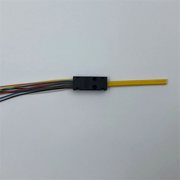
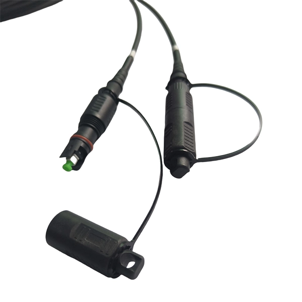
A 4-core fiber optic cable is a type of cable that contains four individual optical fibers within a single protective jacket. These fibers are used to transmit data as light signals, offering high-speed data transfer capabilities over long distances with minimal loss. This guide covers everything you need to know about 4 core fiber, including its internal structure, TIA standard color coding, and how to choose the right type. They are used to connect final user to FTTH or GPON line. Jera is a direct manufacturer who supply a wide range product for. This cable can be used for LAN and WAN backbones, telecom access lines, fibre to business and fibre to the building or the homme connections. It is equally suited for installation in ducts and on trays. This cable features a 0. 15mm corrugated steel armour which makes it rodent proof. OM3 and higher. A TOSLINK optical fiber cable with a clear jacket. What is a 4 Core Optical Cable? A 4 Core Optical Cable is a fiber optic cable that contains four individual optical fibers within a single. Unlike copper wires, which are limited by lower data transmission speeds, shorter transmission distances, and higher susceptibility to electromagnetic interference, fiber optic cables offer unparalleled performance and can cover much greater distances without bumping up against signal degradation.
[PDF]
Lasers, modulators, and photodiodes form the core architecture of optical transceivers, enabling light-speed communication across global networks. Lasers generate the optical carrier. Modulators encode digital information. An optical transmitter is a crucial device used in fiber optic communication systems. Its primary function is to convert electrical signals into optical signals It involves modulating electronic system data and transforming it into light pulses using a laser or LED, and sending the pulses through. The optical transmitter and the optical receiver are the core components that enable this process, forming the electronic-to-optical and optical-to-electronic gateways necessary for modern, high-capacity data transmission. It takes data from an electronic system, uses a laser or LED to modulate that data into pulses of light, and then sends those pulses down the fiber. Together, lasers, modulators, and. At the core of a fiber optic system is the optical fiber – a flexible, transparent strand of glass, thinner than a human hair. Optical fiber is formed by drawing glass or plastic to a diameter slightly thicker than that of a. What are the main elements of an optical transmitter? Data decoder/demodulator, electrical interface, detector, optical interface.
[PDF]
In 2024, Top exporters of Optical fibre cables, made up of individually s are China ($2,363,805. 65K, 379,127,000 Kg), United States ($1,645,814. 71K ), Mexico ($1,313,955. 67K, 18,156,300 Kg). 17 billion (according to external trade statistics of 117 countries). There are no trade data (2023) for such exporters as Korea. Asian countries collectively account for nearly 50% of global exports, with China dominating in both sectors. Looking at both optical fiber and optical cable, China ranks first with an export share of 29. 6%, followed by the United States (12%) and Mexico (11%), which shows that technology is highly. Volza's Big Data technology analyzes over 3. 5 billion verified shipment records across 203 countries to help exporters and importers identify new Fiber Optical Cable buyers and suppliers, discover profitable markets, and connect with reliable trade partners worldwide. According to Volza's Global. Analyze Fiber Optical Cable export import data and locate key markets, reliable suppliers, and active buyers by utilizing Eximpedia's data-centric platform. Whether you're a supplier looking for high-demand markets or a buyer sourcing Fiber Optical Cable from reliable exporters, Eximpedia's. Find verified buyers and sellers of fiber optic cables in 180+ countries along with their valid phone numbers and email ids. The top 3 Buyer countries for fiber optic cables are “ CHINA ”, “ UKRAINE ”, “ UNITED STATES OF AMERICA ”,.
[PDF]
An optical module is a typically hot-pluggable optical transceiver used in high-bandwidth data communications applications. Optical modules typically have an electrical interface on the side that connects to the inside of the system and an optical interface on the side that connects to the outside world through a fiber optic cable. The form factor and electrical interface are often specified by an int. Electrical Interface TypesThere have been multiple variants of the electrical interface of optical modules that have been used over the years. The earliest forms of optical modules had an analog electrical interface. In the transmit dir. Many different forms of optical modulation and multiplexing have been employed in optical modules. The most common modulation technique historically has been or NRZ.
[PDF]
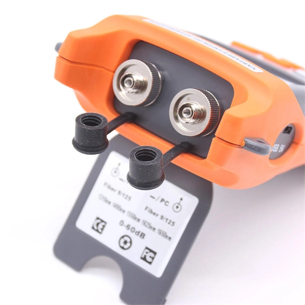
An optical time-domain reflectometer (OTDR) is an optoelectronic instrument used to characterize an optical fiber. It is the optical equivalent of an electronic time domain reflectometer which measures the impedance of the cable or transmission line under test. An OTDR injects a series of optical pulses into the fiber under test and extracts, from the same end of the fiber, light that is scatter. Reliability and quality of OTDR equipmentThe reliability and quality of an OTDR is based on its accuracy, measurement range, ability to resolve and. The common types of OTDR-like test equipment are: 1. Full-feature OTDR: 2. Hand-held OTDR and Fiber break locator: 3. RTU in RFTSs:. In the late 1990s, OTDR industry representatives and the OTDR user community developed a unique data format to store and analyze OTDR fiber data. This data was based on the specifications in GR-196, G.
[PDF]
Optical modulators are used in optical communication systems to encode data onto light waves for transmission through optical fibers. The modulator encodes the data onto the light wave by modifying its amplitude, phase, or frequency. 📦 For purchasing, use the RP Photonics Buyer's Guide for optical modulators. It provides an expert-curated supplier directory, buyer-focused technical background information, and structured selection criteria to support professional procurement decisions. What are Optical Modulators? An optical. Optical modulators are devices that modify the properties of light, such as its amplitude, phase, frequency, or polarization, in response to an external signal. These devices play a crucial role in modern optics and photonics, enabling the manipulation of light for various applications. The beam may be carried over free space, or propagated through an optical waveguide (optical fibre). It acts as the “translator” between the electronic and photonic worlds. They enable the modification of optical wave characteristics such as the intensity, phase, polar-ization, and frequency of light signals. There are basically two types of modulators: bulk and integrated-optic.
[PDF]