An optical power meter is an electronic device that measures the power of an optical signal. It helps engineers verify the performance of optical fiber systems, ensuring that the signal strength meets requirements, and is an essential tool for communication network maintenance and. An optical power meter (OPM) is a device used to measure the power in an optical signal. Other general purpose light power measuring devices are usually called radiometers, photometers, laser power meters (can be. An optical power meter (OPM) measures the power levels of light signals in devices that transmit data or power using light. The term "optical power meter" may sound generic, but in popular usage, it specifically implies a fiber optic power meter. For light power measurements outside the field of. Optical Power Meters (OPMs) are crucial instruments in the field of optical sensors and fiber optic communications. It provides an expert-curated supplier directory, buyer-focused technical background information, and structured selection criteria to support professional procurement decisions. It measures optical power directly, and it is also used in loss testing when paired with a stable light source.
[PDF]
Your AC unit won't turn on after a breaker trips, so check your fuse box and reset the breaker to repair an AC unit. Costs range from $130 to $3,000 to repair an AC unit, with average costs around $350 based on the repair. Use the information below to estimate how much electricity an appliance is using and how much the electricity costs so you can decide whether to invest in a more energy-efficient appliance. Simply connect any appliance to the Kill A Watt EZ, it will then assess how efficient each appliance really is. They were not intended to be prescriptive in terms of what people should build, but they do stipulate important dos and don'ts – many of which. Atomic Energy Act of 1954, secs. 11, 53, 63, 65, 81, 103, 104, 161, 170H, 182, 186, 223, 234, 274, 1701 (42 U. 2014, 2073, 2093, 2095, 2111, 2133, 2134, 2201, 2210h, 2232, 2236, 2273, 2282, 2021, 2297f); Energy Reorganization Act of 1974, secs. 5841, 5842); Low-Level. EPA and the Centers for Disease Control and Prevention (CDC) agree that there is no known safe level of lead in a child's blood. Taking action to reduce these exposures can improve outcomes. Lead is harmful to health, especially for children. On this page: General Information about Lead in Drinking.
[PDF]
Simply put, the output or transmit power (TX Power) is the strength of the signal that's leaving the device. This should fall within a specific range determined by the capabilities of the transmitter. Optical power is the degree of energy that comes from optical signals, which is one of the key parameters of a WDM system. The. In this section, we will learn how to do the following things: Determine the gain of a laser ampli er Find the threshold gain of a cavity Predict the output power of a laser Determine the output mode of the laser Unless otherwise stated, steady state ( d = 0) behavior may dt be assumed. When the signal received is outside of the range, there is a. When it comes to evaluating the performance of an optical transceiver, two key factors come to the fore: Output power (TX Power) and Receiver Sensitivity (RX Sensitivity). An understanding of these concepts is pivotal to establishing an effective and efficient optical network. This comprehensive. As an essential component of optical fiber communication, optical modules are optoelectronic devices that facilitate the conversion between optical and electrical signals during the transmission process. Transmitter power characterizes the average optical power output from the laser under rated conditions, while receiver sensitivity indicates the minimum.
[PDF]
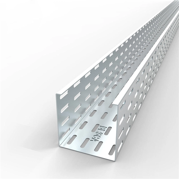
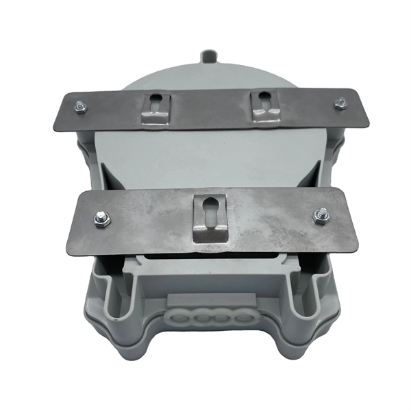
The most common and effective solution is the preformed tension clamp. This fitting consists of a set of helical rods that are wrapped around the cable, a thimble (clevis), and an extension link. The helical rods are designed to transfer the tensile load from the cable to the anchor. The function of the remaining cable rack is to store reserved optical cables, which are generally used on tensile towers (poles). There are two types: Inner button and outer disc. When the remaining cable rack is used for installation on the iron tower, it is equipped with two small splints. Additionally, adapters are available for the steel towers and steel and concrete poles. maintain alignment of and. ficing corrosion resistance. It is best suited to applications with moderate to low span ut increasing fibre strain. 3mm2 RRU Power cable. Without additional adapters, these clamps can provide sturdy, reliable, long-term support to systems. We manufacture a wide range of hardware fittings for OPGW Optical Ground Wire, including Suspension and Tension Assemblies, Down Lead clamps, Earthing Clamps, Splice Enclosure, Reinforcing Rods, Vibration Dampers, etc. Find many great new & used options and get the best deals for 5x Huawei Optical Cable Fixing Clamp 2x3 C Type Bracket Cable Clamp 27150086 at the best online prices at eBay! Free shipping for many products!.
[PDF]
The most common causes of a fluctuating multimeter reading is due to a bad connection or loose wiring in the circuit. In order to investigate this possibility you will need to thoroughly inspect all of your connections and wires for any signs of oxidation, corrosion, fraying or. However, what happens when your multimeter starts behaving erratically, displaying fluctuating readings instead of stable values? This seemingly minor issue can lead to misdiagnosis, wasted time, and even potential safety hazards. Understanding the reasons behind a jumping multimeter reading is. The reading displayed on the meter is affected by factors like voltage drop across components in the circuit being tested. If this reading keeps jumping around unexpectedly it could indicate a problem in the circuit itself. Measuring Current: For current measurement, I switch the multimeter to the current setting. This method allows me to see how much current flows through. This guide delves into the various causes of multimeter fluctuations and provides practical solutions to ensure accurate. From fluctuating readings to unresponsive display screens, recognizing these common issues early on can prevent costly mistakes and potential hazards. These types of issues can often be fixed by replacing faulty wiring and securing.
[PDF]
In this video, we'll show you how to connect an energy meter to a distribution board (DB) safely and efficiently. energy meter connection with distribution box How to Connect an Energy Meter to Your Distribution Box Easily Steps to Properly Connect Your Energy Meter to a Distribution Box. Site/existing equip info - SFH (1 story, no basement, just crawlspace) w/ attached garage. 200A main service (Leviton panel). Covers wiring, placement, standards, and expert tips for a compliant setup. A distribution box is the heart of any electrical system. It takes the incoming power and safely distributes it to different circuits throughout your building. I am going to start digging a trench to run underground cable from a service pole breaker box to a well house; the distance is 60 feet. The breaker is a 240 V 2-pole 20-20 which will run to the well house water pump pressure switch. The present UF 2-10 AVG with ground cable runs two inches under. An electric meter box wiring diagram is a visual representation of the electrical connections and circuits involved in connecting an electric meter to the rest of the electrical system in a building. The diagram provides a clear and concise overview of how the meter is connected to the electrical. Limited the meter location from pad mount transformer for PSO. APCo and TX do not allow unistrut for installations. 7/2020 Revised Figure 15. Added wording for consistency with Section 8 of document.
[PDF]
It performs error detection and alarm monitoring, serving as an essential tool for bit error testing in R&D and production of optical modules/ devices. Bit Error Ratio Tester is an instrument used to test and analyze bit error ratio in digital transmission systems, fiber optic communication systems, and digital microwave communication systems. Dimension Technology's BERT800 bit error tester series offers a comprehensive solution for testing and verifying high-speed optical transceiver modules. OPTELLENT is a provider of broadband test and measurement solutions for communications. The Company's test & measurement solutions are used in product development, manufacturing. As transmission rates continue to accelerate, accurately measuring bit error rates in optical modules is crucial to ensure reliable performance. There are three interchangeable slot boards which include QSFP, SFP+ and SFP ports separately. QSFP, SFP+ and SFP ports follow QSFP MSA, SFP+ MSA and SFP MSA. The user interface allows you to individually monitor bit error rate, error count and timer by connecting to PC via USB cable. In high-speed digital communication systems, even the smallest bit-level error can compromise performance, reduce efficiency, or lead to costly rework.
[PDF]
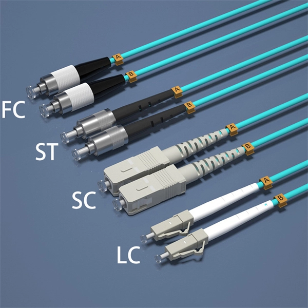
This guide provides a fully updated and industry-ready overview of LC fiber optics, explaining the origin and design of LC connectors, their key features, and the complete ecosystem of LC-based products used in modern networking. LC fiber connectors, as the most well-known representative of SFF (Small Form Factor) connector, are widely adopted in today's LAN and data center cabling. You may find LC connector has a strong family which includes but not limited to LC optical fiber connectors, LC fiber patch cables, LC fiber. Data centers will keep dominating optical module demand as AI and cloud drive revenue growth through 2030. Optical module demand is being pulled in two directions at once, faster bandwidth for dense networks and tighter constraints on power, security, and lead times. With global R&D projected to. LightCounting has proudly served our industry for 22 years with reports and services designed to help executives plan and run their businesses. We support decision-making based on our data, expert analysis and trusted forecasts. It covers LC connectors, LC patch cables, uniboot designs, armored. Optical Module Package Market was valued at 8942 million in 2024 and is projected to reach US$ 20220 million by 2032, at a CAGR of 12. With the surge in data traffic and the increasing demand for higher bandwidth, 100G optical modules have gained immense traction. These modules facilitate high-speed.
[PDF]
A WDM system uses a multiplexer at the transmitter to join the several signals together and a demultiplexer at the receiver to split them apart. With the right type of fiber, it is possible to have a device that does both simultaneously and can function as an optical add-drop. In fiber-optic communications, wavelength-division multiplexing (WDM) is a technology which multiplexes a number of optical carrier signals onto a single optical fiber by using different wavelengths (i., colors) of laser light. This technique enables bidirectional communications over a. WDM is a fiber optic transmission technique that leverages multiple light wavelengths to transmit data efficiently over a single medium. WDM technology employs different optical wavelengths, or colors, of laser light to multiplex several optical carrier signals onto a solitary optical fiber. Each. There are a lot of people who don't understand the difference between WDM and optical splitter. This allows multiple channels of data to be transmitted simultaneously. WDM technologies allow organizations to place equipment at either end of a fiber pair and combine multiple wavelength channels on a single fiber pair instead of using multiple separate fibers pairs for every separate service. The article explains the fundamental principle and its.
[PDF]
This document is a guideline for the key features, installation, and maintenance practices conducted on this type of machinery. Readers who go through performance and technical specifications will be able to learn how and where best to utilize the cable reels in a target. OCC's Modular Advanced Reel System (MARS ®), the industry's first lightweight cable deployment reel system, is designed specifically for the demanding needs of harsh-environment fiber optic installations. Unlike traditional metal-style reels, MARS is a lightweight, modular. Explore our comprehensive selection of fiber optic cable reels and spools, including custom steel and plastic options. Engineered for secure cable storage and transportation with precision fabrication to customer specifications. Our reels serve wire and cable manufacturers, offering durable. Our field drum is designed for handling fiber cables in temporary networks. It is available in three sizes, accommodating 100, 250, or 500 meters of cable. The specified capacity is based on a 5. 5 mm (4-fiber) field cable. All. Download Datasheet PDF OPTICAL CABLE REEL Ruggedised fibre optic assembly for field deployable applications. Aplications : • Broadcasting • Emergency.
[PDF]
These beamsplitters are made by coating the hypotenuse of dual prisms with a partially reflecting material and joining them together using optical or epoxy cement. They eradicate the ghosting phenomenon because the transmitted beam is consistent with the incident light beam. A beam splitter or beamsplitter is an optical device that splits a beam of light into a transmitted and a reflected beam. It is a crucial part of many optical experimental and measurement systems, such as interferometers, also finding widespread application in fibre optic telecommunications. This division allows for the simultaneous analysis or utilization of the light's properties along two separate paths. These tools can split both laser and regular light. Image Credit: Shanghai Optics Most plate beamsplitters are. 📦 For purchasing, use the RP Photonics Buyer's Guide for beam splitters. It provides an expert-curated supplier directory, buyer-focused technical background information, and structured selection criteria to support professional procurement decisions. Beamsplitters are often classified according to their construction: cube or plate. Beam splitters are used to manipulate and control light, making them valuable devices in both classical and quantum optics. A beam splitter is capable of introducing phase shifts and quantum superpositions, making them a core component of quantum technologies such as quantum computing and Quantum.
[PDF]
XGS-PON is a 10 Gbps symmetric passive optical network (X=10, S=symmetric). Optical fiber's greater transmission capacity and speed deliver upstream and downstream (symmetric) speeds of up to 10 Gbit/s (gigabits per second) on the road to connecting users in the last. 10G-PON (also known as XG-PON or G. 987) is a 2010 computer networking standard for data links, capable of delivering shared Internet access rates up to 10 Gbit/s (gigabits per second) over optical fibre. This is the ITU-T 's next-generation standard following on from GPON or gigabit-capable PON. It is commonly used to implement the link to the customer (the last kilometre, or last mile) of fibre-to-the-premises (FTTP) services, using a. Short on Ethernet ports and looking to connect an extra device or two to your wired network setup? You're likely to encounter two options: an Ethernet splitter, and an Ethernet switch. Here's why you should choose the switch every time. What Is an Ethernet Splitter? An Ethernet splitter is a simple. Recommendation ITU-T G. 1 describes a flexible optical fibre access network capable of supporting the bandwidth requirements of business and residential services and covers systems with nominal line rates of 2. 4 Gbit/s in the downstream direction and 1. 984 G-PON and ITU-T G. 9807 XGS-PON wavelengths to coexist within the same single mode fiber cabling and across the same passive optical distribution splitters. This means that users can.
[PDF]
It is 827 kilometres (514 mi) long and was activated in 2013. It has cable landing points at Sopu, a suburb of Nukuʻalofa in Tonga, and Suva, Fiji. The project was funded by Asian Development Bank and the World Bank. With reliable digital connectivity vital to Tonga's economy, the AIFFP is working with partners to provide critical redundancy for Tonga's undersea cable network. We're working with the Governments of Tonga and New Zealand to build a new international undersea telecommunications cable to Tonga. The. The Tonga-Fiji Submarine Cable System (also known as Tonga Cable) is a 827km fiber optic submarine cable system linking Nuku'alofa, Tonga and Suva, Fiji, and connects to the Southern Cross Cable Network at the Suva Cable Landing Station in Fiji. The financial and economic analyses. Tonga Cable Limited is a public enterprise, we are 80% owned by the Government, providing reliable, safe and affordable high speed internet as its core service. Tonga Cable Limited was formed in November 2009, with approval of Government of Tonga, to build and manage a submarine fibre optic cable. In my previous analysis from August 2024, I explored the vulnerability of Tonga's fiber optic submarine cable infrastructure, proposing satellite broadband as a more resilient connectivity solution. Recent events have only reinforced that assessment. As reported on Matangi Tonga, Tonga's domestic.
[PDF]
• Hollow-Core Fiber market size has reached to $1. 23 billion in 2025 • Expected to grow to $2. 1% • Growth Driver: Increasing Demand For High-Speed Internet Connectivity Fueling The Market Growth Due To Digital. The global Hollow-core Fibers market was valued at US$ 15. 7 million by 2029, growing at a Compound Annual Growth Rate (CAGR) of 30. 5% during the forecast period (2023–2029). 4% from 2026 to 2035. I need the full data tables, segment breakdown, and competitive landscape for detailed regional analysis and revenue estimates. Global Outlook – By Type Of Fiber (Photonic Bandgap Fibers, Anti-Resonant Fibers, Other Specialized Hollow-Core Fibers), By Material (Silica, Polymer, Other Materials), By Manufacturing Process (Extrusion Process, Draw Tower Process, Lasing And Sintering Methods, Other Advanced Manufacturing. » Blog » Hollow Core Fiber: The Next Frontier in Ultra-Low-Latency Optical Networks For years, fiber-optic innovation focused on sending more data through glass. The next breakthrough may come from removing the glass entirely. Hollow Core Fiber (HCF) replaces the traditional solid glass core of. The Global Hollow Core Optical Fiber (HCOF) Market is anticipated to witness robust growth at a CAGR of 17.
[PDF]
Locate Fiber Optic Cables suppliers, manufacturers & distributors in Sweden. Interactive map of Sweden provided. Nexans' range of fiber optic cables includes products intended for data and telecommunications as well as industrial applications. Robust cables for national networks, city networks, rural networks and property networks, for installation indoors, outdoors, in ground pipes, in air systems and in. The Swedish Microwave fiber cables are made as ruggedized cables with narrow bend radius and very good performance to fit together with all our RF over Fiber products. They are all single-mode fiber cables and IP 65 classed when mated. Their product range includes robust cables suitable for various environments, ensuring exceptional performance and fire. Eurolan Uni LT fiber cables are used in backbone, distribution networks or in FTTH solutions. Can be laid indoors as it is or outdoors in pipes. 8 mm gel filled loose tube with 2 - 12 fibers; ø 3. Eurolan LT fiber cables are used in backbone. Air Blown Cables are super slim fiber optic cables to be blown into microducts. Ideal for telecommunications, data centres and networking applications, our fibre optic cables are available in single-mode and multimode configurations.
[PDF]