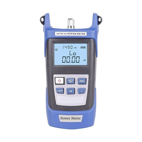
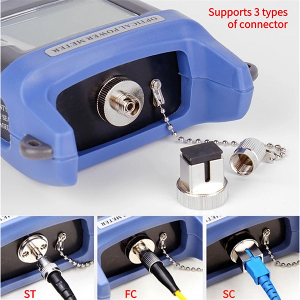
An optical power meter (OPM) works by converting light energy into electrical energy using a photodiode sensor. When light from a fiber optic cable hits the sensor, it generates a small electrical current related to the light's strength. Optical power meters are a key element in the optimization and maintenance of such optical networks and of their components. In this article, learn: What is an optical power meter? An optical power meter (OPM) measures the power levels of light signals in devices that transmit data or power using. An optical power meter (OPM) is a device used to measure the power in an optical signal. The term usually refers to a device for testing average power in fiber optic systems. It measures the optical power transmitted through a fiber, helping to verify if the light signal is strong enough for communication. Beginners may find it complex, but understanding its function makes it. This article provides a comprehensive overview of optical power meters, instruments used to measure the power of light beams. It details the main components, including sensor heads and display units, and explains the two primary sensor technologies: robust thermal sensors for high powers and. A fiber-optic power meter is a quantitative measurement instrument, not a diagnostic tool by itself.
[PDF]
An optical power meter is an electronic device that measures the power of an optical signal. It helps engineers verify the performance of optical fiber systems, ensuring that the signal strength meets requirements, and is an essential tool for communication network maintenance and. An optical power meter (OPM) is a device used to measure the power in an optical signal. Other general purpose light power measuring devices are usually called radiometers, photometers, laser power meters (can be. An optical power meter (OPM) measures the power levels of light signals in devices that transmit data or power using light. The term "optical power meter" may sound generic, but in popular usage, it specifically implies a fiber optic power meter. For light power measurements outside the field of. Optical Power Meters (OPMs) are crucial instruments in the field of optical sensors and fiber optic communications. It provides an expert-curated supplier directory, buyer-focused technical background information, and structured selection criteria to support professional procurement decisions. It measures optical power directly, and it is also used in loss testing when paired with a stable light source.
[PDF]
Absolute optical power calibration of optical power meters, radiometers and photodiodes: From 350 to 1650 nm in 5 nm steps, power range +10 to -60 dBm / 10 mW to 1 nW, with least uncertainty of 0.06 dB.
[PDF]
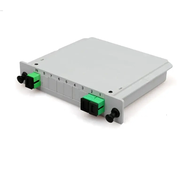
This paper aims to study the design, simulation, and optimization of low-loss Y-branch passive optical splitters up to 64 output ports for telecommunication applications. For a waveguide channel profile, the standard material silica-on-silicon is used. Two important technologies for optical layer monitoring are Optical Performance Monitoring (OPM) and Optical Power Detection (OPD). Although they aim to maintain network health, they differ significantly in scope, technique, and deployment. This article delves into these differences, equipping. Optical Performance Monitoring (OPM) is considered a necessity over an optical network to enable sensibility of traffic line status and attain outstanding Quality-of-Service (QoS). The Y-splitters are designed and simulated at. Passive optical networks (PONs) are the network architecture of choice for residential fiber deployments. A PON is designed specifically to be cost-effective for delivering high data-rates to large customer populations. signals and various components of OPM functionalities are indispensable robust network operation and plays a key role flexibility and improve overall. Optical performance monitoring (OPM) is used for managing high capacity dense wavelength-division multiplexing (DWDM) optical transmission and switching systems in Next Generation Networks (NGN). OPM involves assessing the quality of data channel by measuring its optical characteristics without.
[PDF]
In this video, we'll show you how to connect an energy meter to a distribution board (DB) safely and efficiently. energy meter connection with distribution box How to Connect an Energy Meter to Your Distribution Box Easily Steps to Properly Connect Your Energy Meter to a Distribution Box. Site/existing equip info - SFH (1 story, no basement, just crawlspace) w/ attached garage. 200A main service (Leviton panel). Covers wiring, placement, standards, and expert tips for a compliant setup. A distribution box is the heart of any electrical system. It takes the incoming power and safely distributes it to different circuits throughout your building. I am going to start digging a trench to run underground cable from a service pole breaker box to a well house; the distance is 60 feet. The breaker is a 240 V 2-pole 20-20 which will run to the well house water pump pressure switch. The present UF 2-10 AVG with ground cable runs two inches under. An electric meter box wiring diagram is a visual representation of the electrical connections and circuits involved in connecting an electric meter to the rest of the electrical system in a building. The diagram provides a clear and concise overview of how the meter is connected to the electrical. Limited the meter location from pad mount transformer for PSO. APCo and TX do not allow unistrut for installations. 7/2020 Revised Figure 15. Added wording for consistency with Section 8 of document.
[PDF]
Check the diagnostic information, which shows that the received optical power is low, with a threshold of -3 to -23. 01, currently at -22. Once it exceeds the threshold, an alarm will be triggered. Troubleshoot the link, and if the link is normal, replace the optical. Run the display interface transceiver verbose command in the user view to check whether the transmit optical power (Tx Power) of the interface is within the allowed range. If yes, collect alarm, log, and configuration information, and contact technical support personnel. If the optical module is. An optical module was faulty. Cause 2: Output Optical Power Too High. Services on the optical module may be affected, which may cause bit errors, error packets, or even service interruption. During use, reading optical module information helps understand its real-time operating status, enabling faster troubleshooting of link abnormalities. The following uses the. The International Photonics & Electronics Committee (IPEC) is an international standards organization that is committed to developing open optoelectronic standards and delivering strategic roadmap reports. IPEC focuses on standardizing solutions in optical chips, optical/electrical components, and. The optical module on the port generates an alarm. Often referred as I²C, I2C, IIC (Inter-Integrated Circuit), MDIO (Management Data Input/Output) or CMIS (Common Management Interface Specification), these serial bus.
[PDF]
FBT splitters are more sensitive to fiber bending and environmental expansion, particularly under uneven thermal conditions. A beam splitter or beamsplitter is an optical device that splits a beam of light into a transmitted and a reflected beam. It is a crucial part of many optical experimental and measurement systems, such as interferometers, also finding widespread application in fibre optic telecommunications. a laser beam) into two (or sometimes more) beams, which may or may not have the same optical power (radiant flux). Different types of beam splitters exist, as described in the. Fiber optic splitters distribute optical power from one input fiber to multiple output fibers through either fused biconical taper (FBT) coupling or planar lightwave circuit (PLC) waveguide structures. Their performance depends on optical symmetry, waveguide integrity, and mechanical stability of. : The invention provides a light generating system (1000) comprising a first light generating device (110), a second light generating device (120), a luminescent material (200), a diffuser assembly (700), optical elements (500) comprising a first redirection optical element (1510), and a light exit. When splitting one incident light beam into two separate beams, beamsplitters are applied. Depending on the beam split based on intensity, wavelength, or polarization, its level of optical power on beam penetration differ. Just to mention few, these beamsplitter components are commonly required for.
[PDF]
The most common causes of a fluctuating multimeter reading is due to a bad connection or loose wiring in the circuit. In order to investigate this possibility you will need to thoroughly inspect all of your connections and wires for any signs of oxidation, corrosion, fraying or. However, what happens when your multimeter starts behaving erratically, displaying fluctuating readings instead of stable values? This seemingly minor issue can lead to misdiagnosis, wasted time, and even potential safety hazards. Understanding the reasons behind a jumping multimeter reading is. The reading displayed on the meter is affected by factors like voltage drop across components in the circuit being tested. If this reading keeps jumping around unexpectedly it could indicate a problem in the circuit itself. Measuring Current: For current measurement, I switch the multimeter to the current setting. This method allows me to see how much current flows through. This guide delves into the various causes of multimeter fluctuations and provides practical solutions to ensure accurate. From fluctuating readings to unresponsive display screens, recognizing these common issues early on can prevent costly mistakes and potential hazards. These types of issues can often be fixed by replacing faulty wiring and securing.
[PDF]
The most common and effective solution is the preformed tension clamp. This fitting consists of a set of helical rods that are wrapped around the cable, a thimble (clevis), and an extension link. The helical rods are designed to transfer the tensile load from the cable to the anchor. The function of the remaining cable rack is to store reserved optical cables, which are generally used on tensile towers (poles). There are two types: Inner button and outer disc. When the remaining cable rack is used for installation on the iron tower, it is equipped with two small splints. Additionally, adapters are available for the steel towers and steel and concrete poles. maintain alignment of and. ficing corrosion resistance. It is best suited to applications with moderate to low span ut increasing fibre strain. 3mm2 RRU Power cable. Without additional adapters, these clamps can provide sturdy, reliable, long-term support to systems. We manufacture a wide range of hardware fittings for OPGW Optical Ground Wire, including Suspension and Tension Assemblies, Down Lead clamps, Earthing Clamps, Splice Enclosure, Reinforcing Rods, Vibration Dampers, etc. Find many great new & used options and get the best deals for 5x Huawei Optical Cable Fixing Clamp 2x3 C Type Bracket Cable Clamp 27150086 at the best online prices at eBay! Free shipping for many products!.
[PDF]
To meet the needs of multi-way power distribution applied to high-power solid-state sources, a multi-way power distribution device based on coaxial waveguide is designed and studied. In this work, two dynamically tunable power dividers using waveguide ENZ media are proposed by precisely modulating the internal magnetic field and the widths of the output waveguides. The first approach features a mechanically reconfigurable ring-shaped ENZ waveguide. By analyzing the transmission characteristics of coaxial waveguides and by applying the theory of impedance. In this paper, an E -plane stepped-impedance transformer and Y-junction bifurcation are used to form a waveguide power divider with ceramic substrate loaded with thin film resistors. This structure is realized high isolation in V-band by inserting a ceramic substrate at the H -plane center of the. A numerical model of an equal power divider based on the 4-branch single-mode waveguide is proposed. This proposed design does not require extra fabrication process and supplementary structure modification compared to other typical multibranch waveguides. The condition of uniform output power.
[PDF]
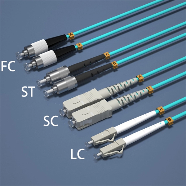
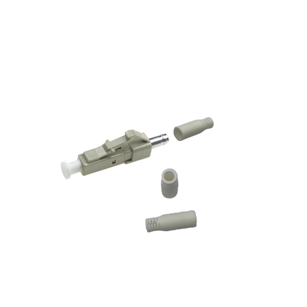
Use the command display transceiver to view the optical module information of all optical ports, and use the command display transceiver interface interface-type interface-number to view the optical module information of a specific optical port. Related Information Video Identify a Huawei-Certified Optical Module Run the display transceiver [ interface interface-type interface-number | slot slot-id ] [ verbose ]. Here is an example on how to query or display optical power of an interface in a Huawei Router. This is tested using NetEngine40E Universal Service Router or NE40E running version 8. The specific viewing information is as follows:. Optical modules are widely used in switches, network interface cards (NICs), routers, and other communication devices. During use, reading optical module information helps understand its real-time operating status, enabling faster troubleshooting of link abnormalities. Transceiver Type : 1000 _BASE_SX_SFP Connector Type :LC Wavelength(nm) : 850 Transfer Distance(m) : 300 (50 um), 150. We want to troubleshoot transceiver on Huawei router, Huawei switch, Huawei systems. 1 Show details, warning etc. from transceivers Check “Alarm information” section for warnings, LOS Alarm means no inbound signal, execute display this to check shutdown mode, execute undo shutdown if necessary.
[PDF]
Calibration & Repair services in Ireland. 5 day turn around with competitive pricing! View full electrical test and measurement equipment list here. is an independent calibration laboratory focused on meeting the total quality requirements of industry. Proper calibration of today's sophisticated test and measurement equipment is essential for preserving measurement accuracy, complying with international standards. Parameters covered include; Temperature, Humidity, Dewpoint, Various Gases, Pressure, Electrical, Weights & Scales, Analytical and some Specialist calibrations. Calibration is performed using the very latest Calibration Equipment/Standards & Calibration/Asset Management Software. Fast Efficient. PTM Calibration offers a wide range of services that complement our core business. We aim to be your one stop shop for all your calibration, test & measurement needs. From major blue chip companies & medium enterprises to small companies and sole traders. Including: aerospace, pharmaceuticals. OptiCal Sciences are an authorised service centre with service, repair and calibration experience and procedures for an extensive variety of models from a wide range of manufacturers.
[PDF]
Full Technical Specifications: Explore our complete range of directional and dual directional couplers, featuring ultra-wideband operation from 0. This catalog details models with coupling values from 5 dB to 50 dB and power ratings up to 500 Watts. How does 6W market outlook report help businesses in making decisions? 6W monitors the market across 60+ countries Globally, publishing an annual market outlook report that analyses trends, key drivers, Size, Volume, Revenue, opportunities, and market segments. This report offers comprehensive. IPP's directional couplers offer some of the widest bandwidths at the highest power levels in the industry. These directional couplers are available in frequencies from 1 MHz., in power. Directional couplers are critical components in radio frequency (RF) and microwave systems, used to split or combine signals while maintaining signal integrity. These passive devices allow a signal to be directed from one port to another, with a portion of the signal being coupled to an auxiliary. We are an RF / Microwave / Wireless Telecom Manufacturer for component, modules and systems. We offer the widest range and best performance RF Directional Couplers and Quadrature Hybrids in the world, extremely aggressive pricing structure. RF directional couplers often. CorechTEK's Directional Couplers are engineered for precise RF and Microwave signal monitoring and power sampling. CorechTEK Couplers.
[PDF]
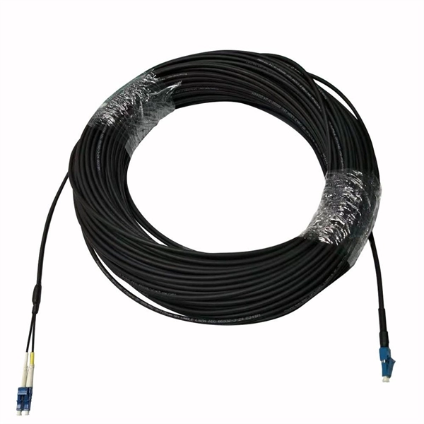
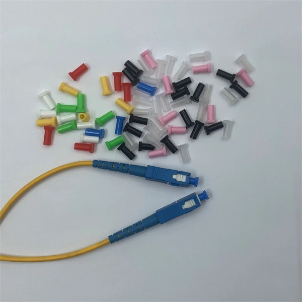
The majority of high-performance telecommunications fibers are manufactured using ultra-pure silica glass, which is silicon dioxide ($text {SiO}_2$). This material forms the two fundamental components of the fiber: the inner Core and the surrounding Cladding. An optical fiber, or optical fibre, is a flexible glass or plastic fiber that can transmit light from one end to the other. To ensure the light signal remains. Single-mode fiber is made from a super-thin fiber core of glass or plastic, through which only one ray of light can travel at a time. This makes it ideal for long-distance data transmission, as there is very little signal loss over distance. However, single-mode fiber requires specialized equipment. Fiber optic cables are made up of a core, cladding, and protective layers, with materials chosen based on the application requirements. What is an optical fiber? It's more than just a piece of glass or. An optical fiber is a single, hair-fine filament drawn from molten silica glass. These fibers are replacing metal wire as the transmission medium in high-speed, high-capacity communications systems that convert information into light, which is then transmitted via fiber optic cable.
[PDF]
Discover 10 Optical Line Terminals manufacturers and distributors on GlobalSpec. Find products, technical articles, videos, and more. Modern OLTs offer communication service providers (CSP) the ability to launch multigigabit services to tens of thousands of subscribers from a single location or just ten. Fiber-to-the-home (FTTH) network operators benefit from deploying OLT solutions that span dense urban, suburban, and rural. Find 10 Optical Line Terminals suppliers with GlobalSpec. The GlobalSpec database includes 62,437 manufacturers and 16,054 distributors headquartered in the United States. Our international database. Explore our range of high-quality GPON, EPON, and XG (S)PON OLT products. NCM Solutions is a leader supplier of FTTH products solution. Optical network terminal (ONT) A single-subscriber device that terminates any one of the distributed (leaf) endpoints of an optical distribution network (ODN), implements a passive optical network (PON) protocol and adapts PON protocol. High-Performance 16-Port XGS-PON OLT with 40G/100G Uplink CapabilityPLANET XGPL-16000 is a high-density 16-Port XGS-PON Optical Line Terminal ( OLT) designed for next-generation fiber broadband access. Product overview GXR101 Pro is an integrated optical access node combining ONU, OLT. A gigabit passive optical network (G-PON) comprises optical line terminals (OLTs) and optical network units (ONUs), and Murata's lineup of products for use in OLTs is introduced here.
[PDF]