An optical power meter is an electronic device that measures the power of an optical signal. It helps engineers verify the performance of optical fiber systems, ensuring that the signal strength meets requirements, and is an essential tool for communication network maintenance and. An optical power meter (OPM) is a device used to measure the power in an optical signal. Other general purpose light power measuring devices are usually called radiometers, photometers, laser power meters (can be. An optical power meter (OPM) measures the power levels of light signals in devices that transmit data or power using light. The term "optical power meter" may sound generic, but in popular usage, it specifically implies a fiber optic power meter. For light power measurements outside the field of. Optical Power Meters (OPMs) are crucial instruments in the field of optical sensors and fiber optic communications. It provides an expert-curated supplier directory, buyer-focused technical background information, and structured selection criteria to support professional procurement decisions. It measures optical power directly, and it is also used in loss testing when paired with a stable light source.
[PDF]

The actual number of optical modules used primarily depends on the following factors. Discrepancies in Calculating the Ratio of Optical Modules to GPU-The Varying Usage Quantity Due to Different Networking Architectures. Network Card Model. GPUs such as the A100, H100, and upcoming GH100 require high-speed optical interconnects to link thousands of GPU nodes, enabling large-scale AI model training and inference. Network Card Model It mainly includes two network cards, ConnectX-6. Traditional optical transceivers, especially in 400G and 800G deployments, generate significant heat and demand substantial power just to keep the lights blinking. 1) NIC Models Mainly includes two types of network cards, ConnectX-6 (200Gb / s, mainly used with the A100) mainly used optical modules are MMA1T00-HS (200G Infiniband HDR QSFP56 SR4 PAM4 850nm 100m) and ConnectX-7. Two complementary approaches are used to grow these systems: scale-up (tightly coupling many accelerators as one unit) and scale-out (networking multiple units across racks or clusters). In both cases, optical connectivity is playing an increasingly vital role. Below, we explain the trends in. While the industry-standard OSFP (Octal Small Form-Factor Pluggable) module has successfully enabled 400Gbps, 800Gbps, and 1. 6Tbps optical pluggable modules , it is limited to 32 modules per Rack Unit (RU), typically requiring 2 RUs to achieve 102. 4Tbps and 4 RUs to reach 204. 8Tbps of switching.
[PDF]

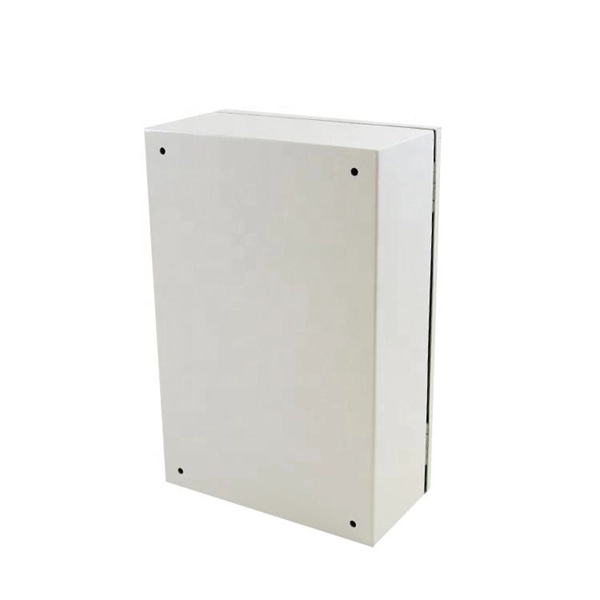
In this video, we'll show you how to connect an energy meter to a distribution board (DB) safely and efficiently. energy meter connection with distribution box How to Connect an Energy Meter to Your Distribution Box Easily Steps to Properly Connect Your Energy Meter to a Distribution Box. Site/existing equip info - SFH (1 story, no basement, just crawlspace) w/ attached garage. 200A main service (Leviton panel). Covers wiring, placement, standards, and expert tips for a compliant setup. A distribution box is the heart of any electrical system. It takes the incoming power and safely distributes it to different circuits throughout your building. I am going to start digging a trench to run underground cable from a service pole breaker box to a well house; the distance is 60 feet. The breaker is a 240 V 2-pole 20-20 which will run to the well house water pump pressure switch. The present UF 2-10 AVG with ground cable runs two inches under. An electric meter box wiring diagram is a visual representation of the electrical connections and circuits involved in connecting an electric meter to the rest of the electrical system in a building. The diagram provides a clear and concise overview of how the meter is connected to the electrical. Limited the meter location from pad mount transformer for PSO. APCo and TX do not allow unistrut for installations. 7/2020 Revised Figure 15. Added wording for consistency with Section 8 of document.
[PDF]
Your AC unit won't turn on after a breaker trips, so check your fuse box and reset the breaker to repair an AC unit. Costs range from $130 to $3,000 to repair an AC unit, with average costs around $350 based on the repair. Use the information below to estimate how much electricity an appliance is using and how much the electricity costs so you can decide whether to invest in a more energy-efficient appliance. Simply connect any appliance to the Kill A Watt EZ, it will then assess how efficient each appliance really is. They were not intended to be prescriptive in terms of what people should build, but they do stipulate important dos and don'ts – many of which. Atomic Energy Act of 1954, secs. 11, 53, 63, 65, 81, 103, 104, 161, 170H, 182, 186, 223, 234, 274, 1701 (42 U. 2014, 2073, 2093, 2095, 2111, 2133, 2134, 2201, 2210h, 2232, 2236, 2273, 2282, 2021, 2297f); Energy Reorganization Act of 1974, secs. 5841, 5842); Low-Level. EPA and the Centers for Disease Control and Prevention (CDC) agree that there is no known safe level of lead in a child's blood. Taking action to reduce these exposures can improve outcomes. Lead is harmful to health, especially for children. On this page: General Information about Lead in Drinking.
[PDF]
Check the diagnostic information, which shows that the received optical power is low, with a threshold of -3 to -23. 01, currently at -22. Once it exceeds the threshold, an alarm will be triggered. Troubleshoot the link, and if the link is normal, replace the optical. Run the display interface transceiver verbose command in the user view to check whether the transmit optical power (Tx Power) of the interface is within the allowed range. If yes, collect alarm, log, and configuration information, and contact technical support personnel. If the optical module is. An optical module was faulty. Cause 2: Output Optical Power Too High. Services on the optical module may be affected, which may cause bit errors, error packets, or even service interruption. During use, reading optical module information helps understand its real-time operating status, enabling faster troubleshooting of link abnormalities. The following uses the. The International Photonics & Electronics Committee (IPEC) is an international standards organization that is committed to developing open optoelectronic standards and delivering strategic roadmap reports. IPEC focuses on standardizing solutions in optical chips, optical/electrical components, and. The optical module on the port generates an alarm. Often referred as I²C, I2C, IIC (Inter-Integrated Circuit), MDIO (Management Data Input/Output) or CMIS (Common Management Interface Specification), these serial bus.
[PDF]

Simply put, the output or transmit power (TX Power) is the strength of the signal that's leaving the device. This should fall within a specific range determined by the capabilities of the transmitter. Optical power is the degree of energy that comes from optical signals, which is one of the key parameters of a WDM system. The. In this section, we will learn how to do the following things: Determine the gain of a laser ampli er Find the threshold gain of a cavity Predict the output power of a laser Determine the output mode of the laser Unless otherwise stated, steady state ( d = 0) behavior may dt be assumed. When the signal received is outside of the range, there is a. When it comes to evaluating the performance of an optical transceiver, two key factors come to the fore: Output power (TX Power) and Receiver Sensitivity (RX Sensitivity). An understanding of these concepts is pivotal to establishing an effective and efficient optical network. This comprehensive. As an essential component of optical fiber communication, optical modules are optoelectronic devices that facilitate the conversion between optical and electrical signals during the transmission process. Transmitter power characterizes the average optical power output from the laser under rated conditions, while receiver sensitivity indicates the minimum.
[PDF]
Calibration & Repair services in Ireland. 5 day turn around with competitive pricing! View full electrical test and measurement equipment list here. is an independent calibration laboratory focused on meeting the total quality requirements of industry. Proper calibration of today's sophisticated test and measurement equipment is essential for preserving measurement accuracy, complying with international standards. Parameters covered include; Temperature, Humidity, Dewpoint, Various Gases, Pressure, Electrical, Weights & Scales, Analytical and some Specialist calibrations. Calibration is performed using the very latest Calibration Equipment/Standards & Calibration/Asset Management Software. Fast Efficient. PTM Calibration offers a wide range of services that complement our core business. We aim to be your one stop shop for all your calibration, test & measurement needs. From major blue chip companies & medium enterprises to small companies and sole traders. Including: aerospace, pharmaceuticals. OptiCal Sciences are an authorised service centre with service, repair and calibration experience and procedures for an extensive variety of models from a wide range of manufacturers.
[PDF]
Are you purchasing a new router or upgrading an old one? Use this tool to find the router that fits your needs. Juniper's single-box Packet Optical convergence solutions help operators simplify operations, lower transport costs, and tap new revenue opportunities. The ACX5400 Series of 1U routers provide power-efficient metro aggregation and support full IP/MPLS functionality. They deliver the performance. AI readiness comprises six pillars: Strategy, Infrastructure, Data, Governance, Talent, and Culture. Is your organization AI ready? Build the bridge between business outcomes and technology with our new interactive tool. Provide outsourced IT and consulting services with a broad technology. Whether you're upgrading enterprise Wi-Fi or need a high-performance enterprise wireless router, finding the right fit is essential. At Meter, we know how important it is to choose a router that delivers on performance, security, and scalability. That's why we've curated this guide to the best. The Huawei FTTR-SME OptiXstar B50 can function an intelligent optical network hub for SMEs by providing converged network, cloud, security, video, and computing services. It can be used to build secure, reliable, ultra-high bandwidth, and ultra-high concurrency all-optical Wi-Fi networks for SMEs. For SMBs, enterprise routers offer. Milesight helps customers in buildings, retail, healthcare, education, and more achieve their goals smarter and faster. Explore Milesight's.
[PDF]
Discover 10 Optical Line Terminals manufacturers and distributors on GlobalSpec. Find products, technical articles, videos, and more. Modern OLTs offer communication service providers (CSP) the ability to launch multigigabit services to tens of thousands of subscribers from a single location or just ten. Fiber-to-the-home (FTTH) network operators benefit from deploying OLT solutions that span dense urban, suburban, and rural. Find 10 Optical Line Terminals suppliers with GlobalSpec. The GlobalSpec database includes 62,437 manufacturers and 16,054 distributors headquartered in the United States. Our international database. Explore our range of high-quality GPON, EPON, and XG (S)PON OLT products. NCM Solutions is a leader supplier of FTTH products solution. Optical network terminal (ONT) A single-subscriber device that terminates any one of the distributed (leaf) endpoints of an optical distribution network (ODN), implements a passive optical network (PON) protocol and adapts PON protocol. High-Performance 16-Port XGS-PON OLT with 40G/100G Uplink CapabilityPLANET XGPL-16000 is a high-density 16-Port XGS-PON Optical Line Terminal ( OLT) designed for next-generation fiber broadband access. Product overview GXR101 Pro is an integrated optical access node combining ONU, OLT. A gigabit passive optical network (G-PON) comprises optical line terminals (OLTs) and optical network units (ONUs), and Murata's lineup of products for use in OLTs is introduced here.
[PDF]
A WDM system uses a multiplexer at the transmitter to join the several signals together and a demultiplexer at the receiver to split them apart. With the right type of fiber, it is possible to have a device that does both simultaneously and can function as an optical add-drop. In fiber-optic communications, wavelength-division multiplexing (WDM) is a technology which multiplexes a number of optical carrier signals onto a single optical fiber by using different wavelengths (i., colors) of laser light. This technique enables bidirectional communications over a. WDM is a fiber optic transmission technique that leverages multiple light wavelengths to transmit data efficiently over a single medium. WDM technology employs different optical wavelengths, or colors, of laser light to multiplex several optical carrier signals onto a solitary optical fiber. Each. There are a lot of people who don't understand the difference between WDM and optical splitter. This allows multiple channels of data to be transmitted simultaneously. WDM technologies allow organizations to place equipment at either end of a fiber pair and combine multiple wavelength channels on a single fiber pair instead of using multiple separate fibers pairs for every separate service. The article explains the fundamental principle and its.
[PDF]
Naficon Liitin Oy, the parent company based out of Finland is one of the most trusted suppliers for telecom, data centers and utility across Northern Europe. Naficon Fiber Optic Manufacturing LLC in Dubai, UAE serves as a major Manufacturing and Supply Centre in the Middle East. We are a leading manufacturer of Optic Fiber Cables in the United Arab Emirates. With advanced technology, strict quality standards. The United Arab Emirates (UAE) is a thriving hub for fiber optic cable manufacturing, offering advanced solutions to meet the region's growing demand for high-speed internet and reliable telecommunications infrastructure. Here, we explore some of the leading fiber optic cable manufacturers in the. The best connection for your application. New web catalogue, with productfinder and new search function. Search the complete range of products of Lapp Group. This website uses cookies and similar technologies (hereinafter "cookies"). Providing a happier, richer future through providing solutions for copper and optical communication for the past 20 Years. Established to meet the evolving needs of the telecommunication infrastructure network, AFOC focuses on delivering innovative, customized, and competitive optic fiber cable products. NAFICON is a fiber industry expert with over 30 years of manufacturing legacy.
[PDF]
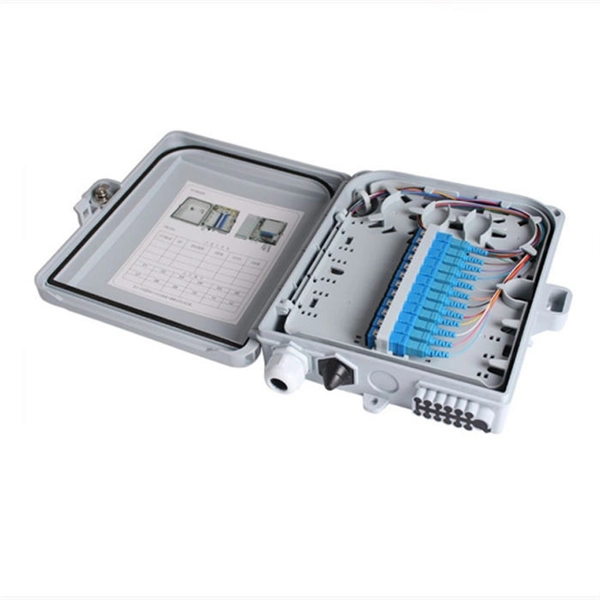
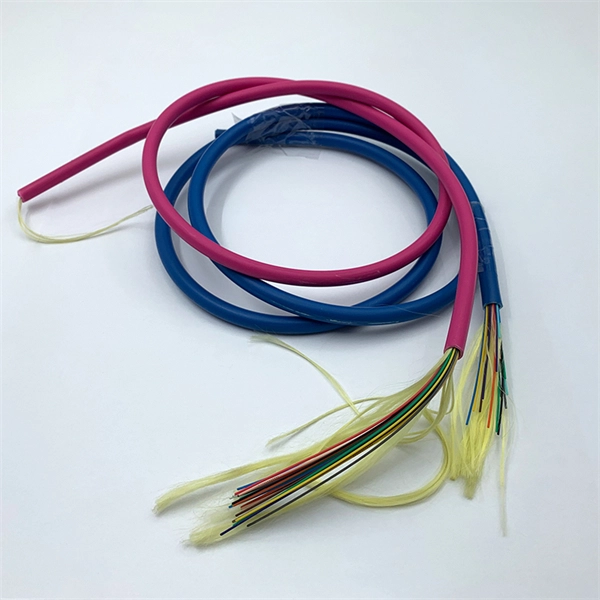
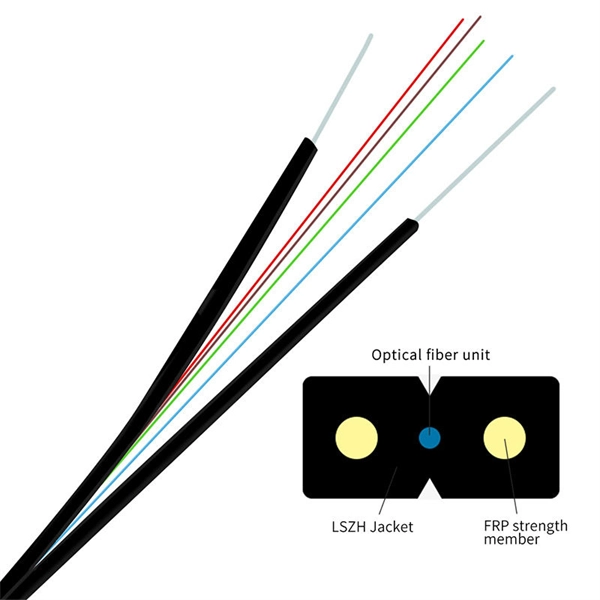
Evenly divide the cables connected to the storage device into two groups. Place the left group of cables into the troughs of the left cable tray, and the right group into those the right. When. In this article, we will explore four key aspects of dividing the wiring sequence and wiring of multi-core cables. This involves determining the optimal path for. Before attempting to split a fiber optic cable, gather the necessary tools and equipment: Fiber Optic Splitter: This device divides a single optical signal into multiple signals. Splitters come in various configurations, such as 1x2, 1x4, or 1x8, depending on how many splits are needed. Route optical fibers inside the cabinet along the posts on the sides of the cabinet and attach. In this video I will show you how to routing a fiber core in a joint enclosure. more In this video I will show you how to routing a fiber core in a joint. When it comes to understanding optical cables, it's essential to grasp the anatomy of these crucial components. An optical cable consists of three primary parts: the core, the cladding, and the protective sheath.
[PDF]
This document discusses techniques for trenching and laying optical fiber ducts. Installing fiber optic cables underground involves far more than digging trenches and placing cables. It forms a critical backbone for modern communication networks across both urban and rural environments. Project success depends on careful planning, precise installation practices, and proper. Installing underground fiber optic cables is critical to establishing high speed internet infrastructure that delivers reliable connectivity for businesses nationwide. Fiber optic cables are the shining stars of modern connectivity, transmitting data at lightning-fast speeds through glass. This comprehensive guide walks through the essential steps and best practices for successful underground fiber optic cable deployment, ensuring optimal performance and longevity of your network installation. Why Choose Underground Fiber Optic Installation? Underground fiber optic installations. Placing cables underground has the added benefits of reducing transmission losses, aiding planning consent and reduced risk of service supply loss through extreme weather.
[PDF]
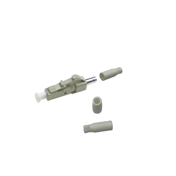
With a powerful 40KM transmission capability and SC interface, this GPON OLT module is fully compatible with Huawei, ZTE, and Cisco devices. Built for carrier-grade reliability, it ensures stable, high-speed data transmission in fiber-to-the-home (FTTH) and enterprise GPON. The SFP-FE-SX-MM1310 (part number: 02315233) is a Huawei-certified 100M optical module. However, the Vendor Name field displays the original manufacturer name, instead of HUAWEI. Huawei. For Class C+ module, it can support with 64 ONUs at most. OptiXstar MA5671A is a mini plug-and-play Passive Optical Network (PON) access device an Optical Network Unit (ONU) that supports one-stop deployment, even achievable offline when using Gigabit-capable Passive Optical Network (GPON) upstream transmission. Once deployed, OptiXstar MA5671A. Huawei SFP GPON OLT C+ is fit with Huawei OLT devices like MA5608T MA5683T and MA5680T. It is inserted in devices such as routers or network interface cards which provide one or more transceiver module slot. Huawei. Haile GPON OLT Optical Fiber Module SFP-GPON-OLT-40 is a high-performance optical transceiver designed for long-distance fiber optic communication.
[PDF]

At its core, a fiber optic splitter relies on the principles of light reflection, refraction, and waveguiding to divide signals. Its design varies by type, but the underlying mechanism involves manipulating light to distribute its power across multiple output ports. A fiber optic splitter is a passive optical component that divides a single incoming optical signal into two or more outgoing signals, or combines multiple incoming signals into one. Their ability to efficiently manage optical signals makes them indispensable in various. This guide will demystify this pivotal passive device, exploring its types, working principles, and how it seamlessly integrates with optical transceivers to bring high-speed internet to your doorstep. 📄 What is an Optical Splitter? An Optical Splitter, also known as a beam splitter, is a passive. Fiber optic splitter is a passive optical device that includes multiple input and output ends. This principle allows a single input light beam to be split into N output light beams. The splitting can be achieved through two main methods: parallel beam splitting and beam divergence splitting. For example, an optical splitter.
[PDF]