Need some clarification about NEC 770. 47 (B), it says that the direct buried conductive fiber optic cable shall be 12 in (300 mm) away from the power cables. Separating high-voltage power cables from low-voltage communication cables is a fundamental requirement in any electrical installation. This practice is mandatory for two distinct reasons: ensuring the safety of the structure and its occupants, and preserving the integrity of sensitive data. Maintaining proper separation between power, data, and limited energy cabling is foundational to system performance, safety, and code compliance. Separation isn't just an EMI precaution — it protects signaling, reduces rework, and ensures pathways meet inspection expectations across risers. TECHNICAL GUIDELINE July 30, 2020 TG030 Rev. 4 Pathway Separation Between Telecommunication Cables and Power Cables Communications cables are, by design or necessity, often installed in close proximity and/or in the same pathway as power service cables. The electrical energy of the power cables can. This standard titled “Commercial Building Standard for Telecommunications Pathways and Spaces” is a joint publication of ANSI/TIA/EIA. Its current version (ANSI/TIA/EIA/-569-B) was published in October 1, 2004 and describes EMI aspects in Article 10. ca with numerous contributions by others. "UTP Separation Guidelines From EMI Sources". The values are the same as the cabling pathways standard, EIA-569, table 4.
[PDF]
Simply put, the output or transmit power (TX Power) is the strength of the signal that's leaving the device. This should fall within a specific range determined by the capabilities of the transmitter. Optical power is the degree of energy that comes from optical signals, which is one of the key parameters of a WDM system. The. In this section, we will learn how to do the following things: Determine the gain of a laser ampli er Find the threshold gain of a cavity Predict the output power of a laser Determine the output mode of the laser Unless otherwise stated, steady state ( d = 0) behavior may dt be assumed. When the signal received is outside of the range, there is a. When it comes to evaluating the performance of an optical transceiver, two key factors come to the fore: Output power (TX Power) and Receiver Sensitivity (RX Sensitivity). An understanding of these concepts is pivotal to establishing an effective and efficient optical network. This comprehensive. As an essential component of optical fiber communication, optical modules are optoelectronic devices that facilitate the conversion between optical and electrical signals during the transmission process. Transmitter power characterizes the average optical power output from the laser under rated conditions, while receiver sensitivity indicates the minimum.
[PDF]
FBT splitters are more sensitive to fiber bending and environmental expansion, particularly under uneven thermal conditions. A beam splitter or beamsplitter is an optical device that splits a beam of light into a transmitted and a reflected beam. It is a crucial part of many optical experimental and measurement systems, such as interferometers, also finding widespread application in fibre optic telecommunications. a laser beam) into two (or sometimes more) beams, which may or may not have the same optical power (radiant flux). Different types of beam splitters exist, as described in the. Fiber optic splitters distribute optical power from one input fiber to multiple output fibers through either fused biconical taper (FBT) coupling or planar lightwave circuit (PLC) waveguide structures. Their performance depends on optical symmetry, waveguide integrity, and mechanical stability of. : The invention provides a light generating system (1000) comprising a first light generating device (110), a second light generating device (120), a luminescent material (200), a diffuser assembly (700), optical elements (500) comprising a first redirection optical element (1510), and a light exit. When splitting one incident light beam into two separate beams, beamsplitters are applied. Depending on the beam split based on intensity, wavelength, or polarization, its level of optical power on beam penetration differ. Just to mention few, these beamsplitter components are commonly required for.
[PDF]
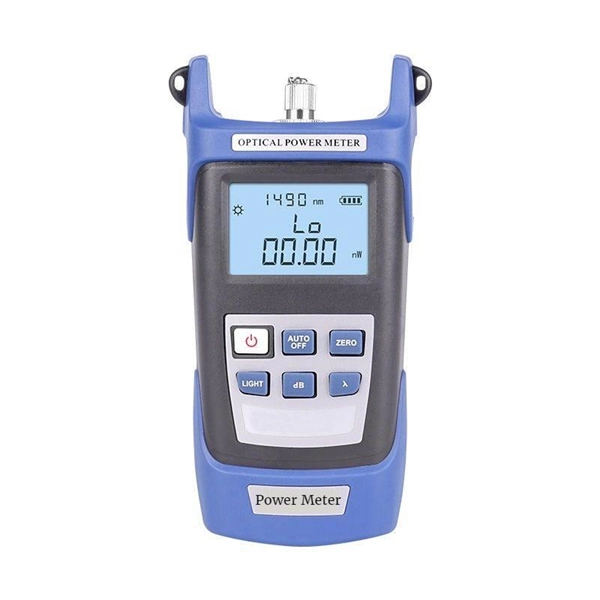
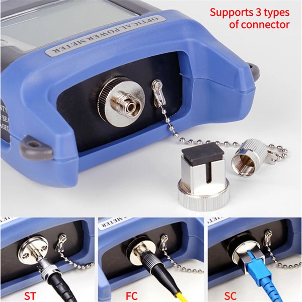
An optical power meter (OPM) works by converting light energy into electrical energy using a photodiode sensor. When light from a fiber optic cable hits the sensor, it generates a small electrical current related to the light's strength. Optical power meters are a key element in the optimization and maintenance of such optical networks and of their components. In this article, learn: What is an optical power meter? An optical power meter (OPM) measures the power levels of light signals in devices that transmit data or power using. An optical power meter (OPM) is a device used to measure the power in an optical signal. The term usually refers to a device for testing average power in fiber optic systems. It measures the optical power transmitted through a fiber, helping to verify if the light signal is strong enough for communication. Beginners may find it complex, but understanding its function makes it. This article provides a comprehensive overview of optical power meters, instruments used to measure the power of light beams. It details the main components, including sensor heads and display units, and explains the two primary sensor technologies: robust thermal sensors for high powers and. A fiber-optic power meter is a quantitative measurement instrument, not a diagnostic tool by itself.
[PDF]
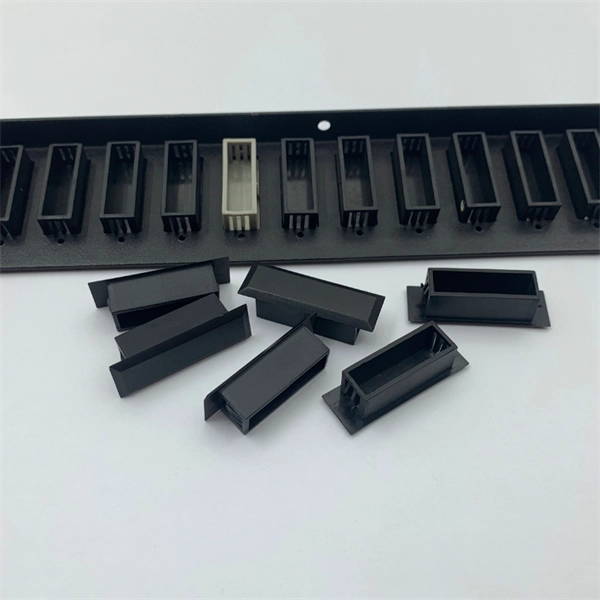
The most common and effective solution is the preformed tension clamp. This fitting consists of a set of helical rods that are wrapped around the cable, a thimble (clevis), and an extension link. The helical rods are designed to transfer the tensile load from the cable to the anchor. The function of the remaining cable rack is to store reserved optical cables, which are generally used on tensile towers (poles). There are two types: Inner button and outer disc. When the remaining cable rack is used for installation on the iron tower, it is equipped with two small splints. Additionally, adapters are available for the steel towers and steel and concrete poles. maintain alignment of and. ficing corrosion resistance. It is best suited to applications with moderate to low span ut increasing fibre strain. 3mm2 RRU Power cable. Without additional adapters, these clamps can provide sturdy, reliable, long-term support to systems. We manufacture a wide range of hardware fittings for OPGW Optical Ground Wire, including Suspension and Tension Assemblies, Down Lead clamps, Earthing Clamps, Splice Enclosure, Reinforcing Rods, Vibration Dampers, etc. Find many great new & used options and get the best deals for 5x Huawei Optical Cable Fixing Clamp 2x3 C Type Bracket Cable Clamp 27150086 at the best online prices at eBay! Free shipping for many products!.
[PDF]
To meet the needs of multi-way power distribution applied to high-power solid-state sources, a multi-way power distribution device based on coaxial waveguide is designed and studied. In this work, two dynamically tunable power dividers using waveguide ENZ media are proposed by precisely modulating the internal magnetic field and the widths of the output waveguides. The first approach features a mechanically reconfigurable ring-shaped ENZ waveguide. By analyzing the transmission characteristics of coaxial waveguides and by applying the theory of impedance. In this paper, an E -plane stepped-impedance transformer and Y-junction bifurcation are used to form a waveguide power divider with ceramic substrate loaded with thin film resistors. This structure is realized high isolation in V-band by inserting a ceramic substrate at the H -plane center of the. A numerical model of an equal power divider based on the 4-branch single-mode waveguide is proposed. This proposed design does not require extra fabrication process and supplementary structure modification compared to other typical multibranch waveguides. The condition of uniform output power.
[PDF]
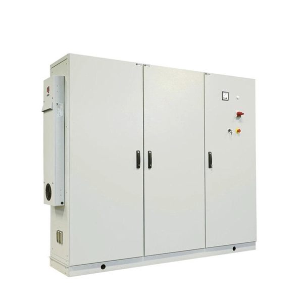
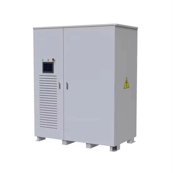
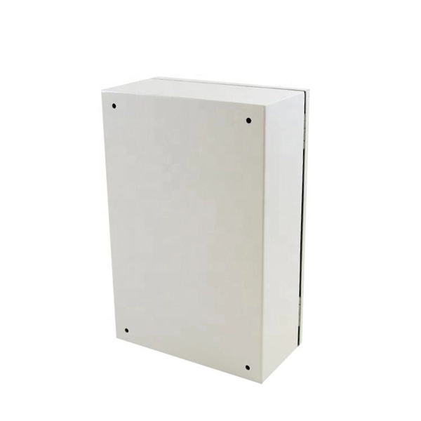
With vast rural areas lacking grid access, battery energy storage systems (BESS) provide reliable electricity for communities and industries. Imagine a solar farm in the Andes storing excess dayt Bolivia's growing energy demands and remote terrain make the BESS outdoor power . As Bolivia's fastest-growing urban center, Santa Cruz faces unique energy demands that require robust outdoor power solutions. Whether you're a homeowner seeking backup options or a business owner. Imagine a solar farm in the Andes storing excess dayt. The world"s largest PV-diesel hybrid power plant system with battery storage was commissioned in December 2014, in the Bolivian province of Pando. SMA is not only supplying photovoltaic inverters Bolivia"s growing industrial and commercial sectors demand stable power solutions. Whether you're a homeowner seeking backup options or a business owner. Aug 13, 2025 · How We Selected and Tested To pick the best solar generators, we tested some of these power stations for charging capacity, Aug 29, 2025 · Bolivia"s solar development has reached a new height of a 3MW ground solar project, the largest solar plant in the private sector within the. If you are looking for Electrical Panel, we have LT Distribution Panel, Load Management Panel, Outdoor Power Panel, Marshalling Panel, and Power Control Panel In Bolivia. So get in touch with us for your Panel need. An electrical cable is a current-carrying assembly of wires that runs side by side.
[PDF]
Absolute optical power calibration of optical power meters, radiometers and photodiodes: From 350 to 1650 nm in 5 nm steps, power range +10 to -60 dBm / 10 mW to 1 nW, with least uncertainty of 0.06 dB.
[PDF]
Acceptable dB loss for fiber depends on the component you're measuring: a single mated connector pair should lose no more than 0. 75 dB, a fusion splice should stay under 0. 3 dB, and fiber cable itself loses between 0. To be able to judge whether a fiber optic cable plant is good, one does a insertion loss test with a light source and power meter and compares that to an estimate of what is a reasonable loss for that cable plant. The estimate, called a "loss budget" is calculated using typical component losses for. Q: What is fiber optic loss? A: Fiber optic loss refers to the reduction in signal strength as it travels through the fiber optic cable. This can be due to various factors, including attenuation, connectors, and splices. Q: How is fiber optic loss measured? A: Fiber optic loss is typically measured. Fiber loss can be also called fiber optic attenuation or attenuation loss, which measures the amount of light loss between input and output. 5 dB per kilometer depending on the type and wavelength. The total. Attenuation is the natural loss of signal power over distance. This is inherent in all fiber types and happens even under ideal conditions. Factors such as wavelength and fiber quality influence attenuation. Measured in decibels (dB), loss degrades signal quality, limits distance, increases bit-error rate, and escalates infrastructure cost. Understanding and managing it is critical to.
[PDF]
The optical budget refers to the maximum allowable signal loss between the transmitter and receiver in a fiber-optic link. It ensures that the received signal is strong enough for the equipment to process data without errors. Calculated in decibels (dB), it is the difference between the. After measuring the loss of a fiber link, you now have to determine if that fiber link loss is acceptable or not. You can either compare this loss value to the application requirement or calculate the expected loss based on how many connectors and splices are in the link along with the length of. Optical module channel loss resistance refers to the maximum optical path attenuation that an optical transceiver module can tolerate while still maintaining compliant signal integrity, error performance, and link stability. There are many reasons for optical fiber loss, such as optical fiber material's absorption/scattering of light energy, bending.
[PDF]
Use this selector tool to quickly identify the best power supply for your aerospace and defense ATE requirements. Explore engineer-authored content and a vast knowledge base with thousands of learning opportunities. Use 25+ X-Series applications to analyze, demodulate, and troubleshoot signals across wireless, aerospace/defense, EMI, and phase noise. With extra memory and storage, these enhanced NPBs run Keysight's AI security and performance monitoring software and AI stack. Achieve fast, accurate board-level. Fiber-optic switches control light paths within fiber optics, ranging from simple on/off types to complex matrix configurations like 64×64. Fiber-optic switches are optical switches in the context of fiber optics. They're a core component in fiber-optic networks, where data travels as pulses of light through glass fibers. This technology allows for high bit rate transmission to be switched between various optical lines. All of these optical switches are purely optical path, there is no optical to electrical to optical conversion. Click to jump to class of switch --- Provides a bypass of.
[PDF]
Full Technical Specifications: Explore our complete range of directional and dual directional couplers, featuring ultra-wideband operation from 0. This catalog details models with coupling values from 5 dB to 50 dB and power ratings up to 500 Watts. How does 6W market outlook report help businesses in making decisions? 6W monitors the market across 60+ countries Globally, publishing an annual market outlook report that analyses trends, key drivers, Size, Volume, Revenue, opportunities, and market segments. This report offers comprehensive. IPP's directional couplers offer some of the widest bandwidths at the highest power levels in the industry. These directional couplers are available in frequencies from 1 MHz., in power. Directional couplers are critical components in radio frequency (RF) and microwave systems, used to split or combine signals while maintaining signal integrity. These passive devices allow a signal to be directed from one port to another, with a portion of the signal being coupled to an auxiliary. We are an RF / Microwave / Wireless Telecom Manufacturer for component, modules and systems. We offer the widest range and best performance RF Directional Couplers and Quadrature Hybrids in the world, extremely aggressive pricing structure. RF directional couplers often. CorechTEK's Directional Couplers are engineered for precise RF and Microwave signal monitoring and power sampling. CorechTEK Couplers.
[PDF]
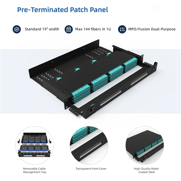
The actual number of optical modules used primarily depends on the following factors. Discrepancies in Calculating the Ratio of Optical Modules to GPU-The Varying Usage Quantity Due to Different Networking Architectures. Network Card Model. GPUs such as the A100, H100, and upcoming GH100 require high-speed optical interconnects to link thousands of GPU nodes, enabling large-scale AI model training and inference. Network Card Model It mainly includes two network cards, ConnectX-6. Traditional optical transceivers, especially in 400G and 800G deployments, generate significant heat and demand substantial power just to keep the lights blinking. 1) NIC Models Mainly includes two types of network cards, ConnectX-6 (200Gb / s, mainly used with the A100) mainly used optical modules are MMA1T00-HS (200G Infiniband HDR QSFP56 SR4 PAM4 850nm 100m) and ConnectX-7. Two complementary approaches are used to grow these systems: scale-up (tightly coupling many accelerators as one unit) and scale-out (networking multiple units across racks or clusters). In both cases, optical connectivity is playing an increasingly vital role. Below, we explain the trends in. While the industry-standard OSFP (Octal Small Form-Factor Pluggable) module has successfully enabled 400Gbps, 800Gbps, and 1. 6Tbps optical pluggable modules , it is limited to 32 modules per Rack Unit (RU), typically requiring 2 RUs to achieve 102. 4Tbps and 4 RUs to reach 204. 8Tbps of switching.
[PDF]
A WDM system uses a multiplexer at the transmitter to join the several signals together and a demultiplexer at the receiver to split them apart. With the right type of fiber, it is possible to have a device that does both simultaneously and can function as an optical add-drop. In fiber-optic communications, wavelength-division multiplexing (WDM) is a technology which multiplexes a number of optical carrier signals onto a single optical fiber by using different wavelengths (i., colors) of laser light. This technique enables bidirectional communications over a. WDM is a fiber optic transmission technique that leverages multiple light wavelengths to transmit data efficiently over a single medium. WDM technology employs different optical wavelengths, or colors, of laser light to multiplex several optical carrier signals onto a solitary optical fiber. Each. There are a lot of people who don't understand the difference between WDM and optical splitter. This allows multiple channels of data to be transmitted simultaneously. WDM technologies allow organizations to place equipment at either end of a fiber pair and combine multiple wavelength channels on a single fiber pair instead of using multiple separate fibers pairs for every separate service. The article explains the fundamental principle and its.
[PDF]
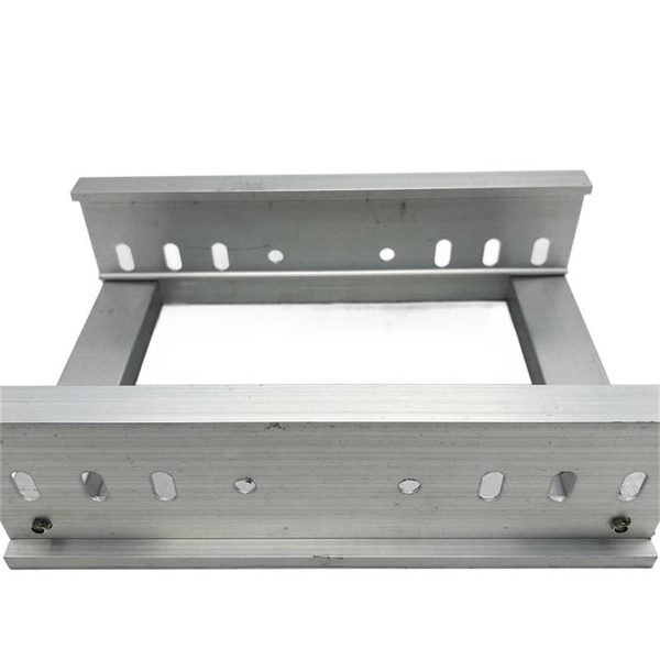
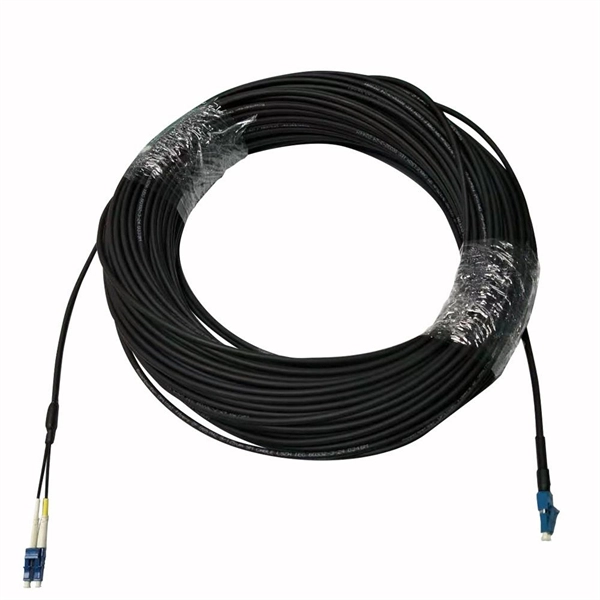
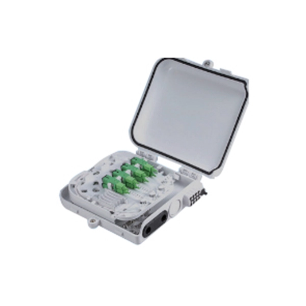
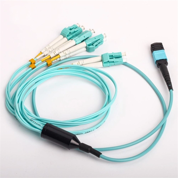
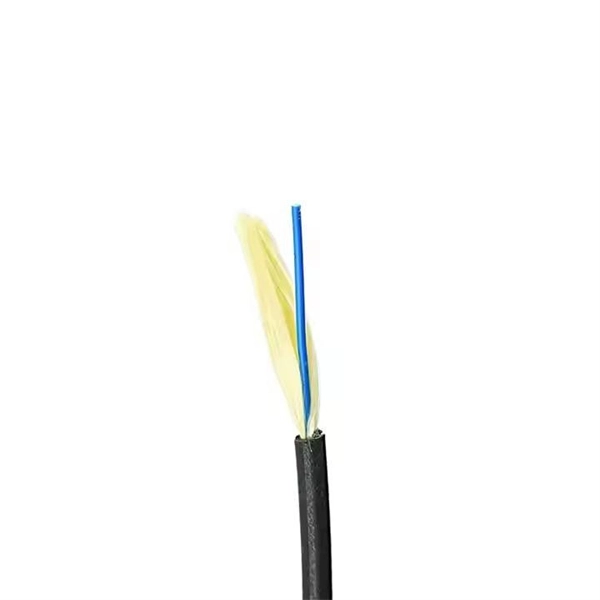
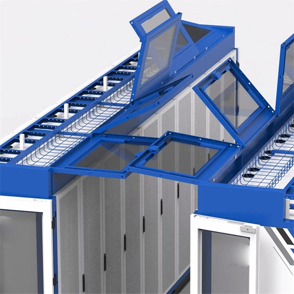
Evenly divide the cables connected to the storage device into two groups. Place the left group of cables into the troughs of the left cable tray, and the right group into those the right. When. In this article, we will explore four key aspects of dividing the wiring sequence and wiring of multi-core cables. This involves determining the optimal path for. Before attempting to split a fiber optic cable, gather the necessary tools and equipment: Fiber Optic Splitter: This device divides a single optical signal into multiple signals. Splitters come in various configurations, such as 1x2, 1x4, or 1x8, depending on how many splits are needed. Route optical fibers inside the cabinet along the posts on the sides of the cabinet and attach. In this video I will show you how to routing a fiber core in a joint enclosure. more In this video I will show you how to routing a fiber core in a joint. When it comes to understanding optical cables, it's essential to grasp the anatomy of these crucial components. An optical cable consists of three primary parts: the core, the cladding, and the protective sheath.
[PDF]