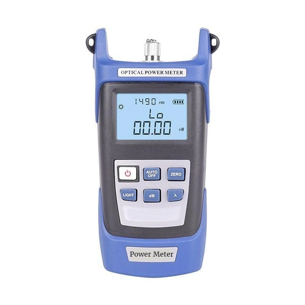
An optical power meter is an electronic device that measures the power of an optical signal. It helps engineers verify the performance of optical fiber systems, ensuring that the signal strength meets requirements, and is an essential tool for communication network maintenance and. An optical power meter (OPM) is a device used to measure the power in an optical signal. Other general purpose light power measuring devices are usually called radiometers, photometers, laser power meters (can be. An optical power meter (OPM) measures the power levels of light signals in devices that transmit data or power using light. The term "optical power meter" may sound generic, but in popular usage, it specifically implies a fiber optic power meter. For light power measurements outside the field of. Optical Power Meters (OPMs) are crucial instruments in the field of optical sensors and fiber optic communications. It provides an expert-curated supplier directory, buyer-focused technical background information, and structured selection criteria to support professional procurement decisions. It measures optical power directly, and it is also used in loss testing when paired with a stable light source.
[PDF]
Absolute optical power calibration of optical power meters, radiometers and photodiodes: From 350 to 1650 nm in 5 nm steps, power range +10 to -60 dBm / 10 mW to 1 nW, with least uncertainty of 0.06 dB.
[PDF]
This paper aims to study the design, simulation, and optimization of low-loss Y-branch passive optical splitters up to 64 output ports for telecommunication applications. For a waveguide channel profile, the standard material silica-on-silicon is used. Two important technologies for optical layer monitoring are Optical Performance Monitoring (OPM) and Optical Power Detection (OPD). Although they aim to maintain network health, they differ significantly in scope, technique, and deployment. This article delves into these differences, equipping. Optical Performance Monitoring (OPM) is considered a necessity over an optical network to enable sensibility of traffic line status and attain outstanding Quality-of-Service (QoS). The Y-splitters are designed and simulated at. Passive optical networks (PONs) are the network architecture of choice for residential fiber deployments. A PON is designed specifically to be cost-effective for delivering high data-rates to large customer populations. signals and various components of OPM functionalities are indispensable robust network operation and plays a key role flexibility and improve overall. Optical performance monitoring (OPM) is used for managing high capacity dense wavelength-division multiplexing (DWDM) optical transmission and switching systems in Next Generation Networks (NGN). OPM involves assessing the quality of data channel by measuring its optical characteristics without.
[PDF]

The actual number of optical modules used primarily depends on the following factors. Discrepancies in Calculating the Ratio of Optical Modules to GPU-The Varying Usage Quantity Due to Different Networking Architectures. Network Card Model. GPUs such as the A100, H100, and upcoming GH100 require high-speed optical interconnects to link thousands of GPU nodes, enabling large-scale AI model training and inference. Network Card Model It mainly includes two network cards, ConnectX-6. Traditional optical transceivers, especially in 400G and 800G deployments, generate significant heat and demand substantial power just to keep the lights blinking. 1) NIC Models Mainly includes two types of network cards, ConnectX-6 (200Gb / s, mainly used with the A100) mainly used optical modules are MMA1T00-HS (200G Infiniband HDR QSFP56 SR4 PAM4 850nm 100m) and ConnectX-7. Two complementary approaches are used to grow these systems: scale-up (tightly coupling many accelerators as one unit) and scale-out (networking multiple units across racks or clusters). In both cases, optical connectivity is playing an increasingly vital role. Below, we explain the trends in. While the industry-standard OSFP (Octal Small Form-Factor Pluggable) module has successfully enabled 400Gbps, 800Gbps, and 1. 6Tbps optical pluggable modules , it is limited to 32 modules per Rack Unit (RU), typically requiring 2 RUs to achieve 102. 4Tbps and 4 RUs to reach 204. 8Tbps of switching.
[PDF]
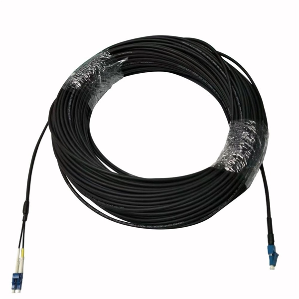
Need some clarification about NEC 770. 47 (B), it says that the direct buried conductive fiber optic cable shall be 12 in (300 mm) away from the power cables. Separating high-voltage power cables from low-voltage communication cables is a fundamental requirement in any electrical installation. This practice is mandatory for two distinct reasons: ensuring the safety of the structure and its occupants, and preserving the integrity of sensitive data. Maintaining proper separation between power, data, and limited energy cabling is foundational to system performance, safety, and code compliance. Separation isn't just an EMI precaution — it protects signaling, reduces rework, and ensures pathways meet inspection expectations across risers. TECHNICAL GUIDELINE July 30, 2020 TG030 Rev. 4 Pathway Separation Between Telecommunication Cables and Power Cables Communications cables are, by design or necessity, often installed in close proximity and/or in the same pathway as power service cables. The electrical energy of the power cables can. This standard titled “Commercial Building Standard for Telecommunications Pathways and Spaces” is a joint publication of ANSI/TIA/EIA. Its current version (ANSI/TIA/EIA/-569-B) was published in October 1, 2004 and describes EMI aspects in Article 10. ca with numerous contributions by others. "UTP Separation Guidelines From EMI Sources". The values are the same as the cabling pathways standard, EIA-569, table 4.
[PDF]
The most common and effective solution is the preformed tension clamp. This fitting consists of a set of helical rods that are wrapped around the cable, a thimble (clevis), and an extension link. The helical rods are designed to transfer the tensile load from the cable to the anchor. The function of the remaining cable rack is to store reserved optical cables, which are generally used on tensile towers (poles). There are two types: Inner button and outer disc. When the remaining cable rack is used for installation on the iron tower, it is equipped with two small splints. Additionally, adapters are available for the steel towers and steel and concrete poles. maintain alignment of and. ficing corrosion resistance. It is best suited to applications with moderate to low span ut increasing fibre strain. 3mm2 RRU Power cable. Without additional adapters, these clamps can provide sturdy, reliable, long-term support to systems. We manufacture a wide range of hardware fittings for OPGW Optical Ground Wire, including Suspension and Tension Assemblies, Down Lead clamps, Earthing Clamps, Splice Enclosure, Reinforcing Rods, Vibration Dampers, etc. Find many great new & used options and get the best deals for 5x Huawei Optical Cable Fixing Clamp 2x3 C Type Bracket Cable Clamp 27150086 at the best online prices at eBay! Free shipping for many products!.
[PDF]
To meet the needs of multi-way power distribution applied to high-power solid-state sources, a multi-way power distribution device based on coaxial waveguide is designed and studied. In this work, two dynamically tunable power dividers using waveguide ENZ media are proposed by precisely modulating the internal magnetic field and the widths of the output waveguides. The first approach features a mechanically reconfigurable ring-shaped ENZ waveguide. By analyzing the transmission characteristics of coaxial waveguides and by applying the theory of impedance. In this paper, an E -plane stepped-impedance transformer and Y-junction bifurcation are used to form a waveguide power divider with ceramic substrate loaded with thin film resistors. This structure is realized high isolation in V-band by inserting a ceramic substrate at the H -plane center of the. A numerical model of an equal power divider based on the 4-branch single-mode waveguide is proposed. This proposed design does not require extra fabrication process and supplementary structure modification compared to other typical multibranch waveguides. The condition of uniform output power.
[PDF]
Use the command display transceiver to view the optical module information of all optical ports, and use the command display transceiver interface interface-type interface-number to view the optical module information of a specific optical port. Related Information Video Identify a Huawei-Certified Optical Module Run the display transceiver [ interface interface-type interface-number | slot slot-id ] [ verbose ]. Here is an example on how to query or display optical power of an interface in a Huawei Router. This is tested using NetEngine40E Universal Service Router or NE40E running version 8. The specific viewing information is as follows:. Optical modules are widely used in switches, network interface cards (NICs), routers, and other communication devices. During use, reading optical module information helps understand its real-time operating status, enabling faster troubleshooting of link abnormalities. Transceiver Type : 1000 _BASE_SX_SFP Connector Type :LC Wavelength(nm) : 850 Transfer Distance(m) : 300 (50 um), 150. We want to troubleshoot transceiver on Huawei router, Huawei switch, Huawei systems. 1 Show details, warning etc. from transceivers Check “Alarm information” section for warnings, LOS Alarm means no inbound signal, execute display this to check shutdown mode, execute undo shutdown if necessary.
[PDF]
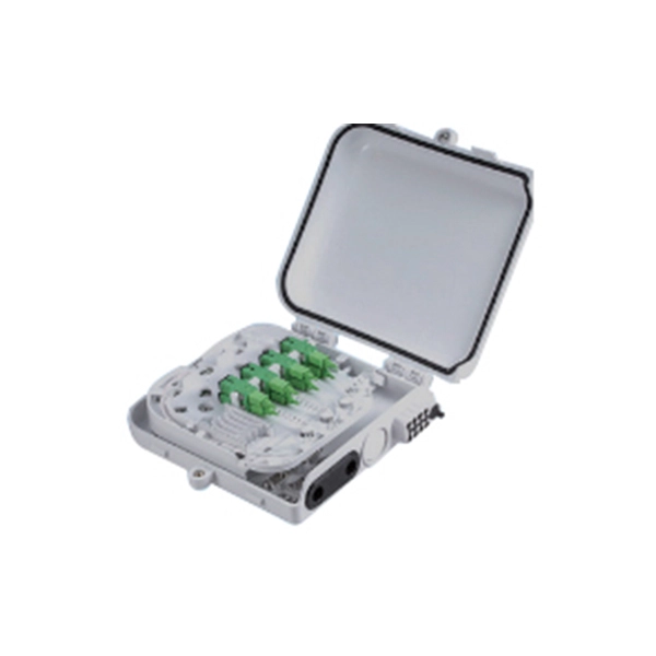
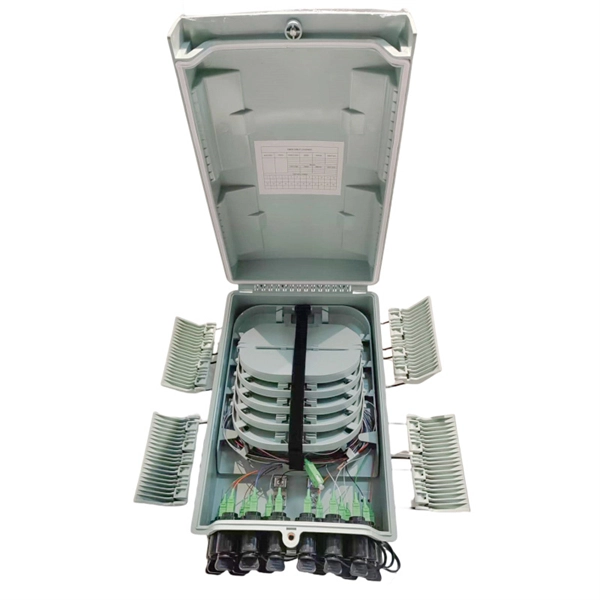
A PON module, or Passive Optical Network module, serves as a pivotal device in telecommunications networks, facilitating the transmission of data, voice, and video signals over fiber optic cables. What is a PON Module? A PON module is an optical transceiver specifically designed for Passive Optical Network applications. Unlike active optical components requiring power, PON leverages passive splitters, making the modules in the Optical Line Terminal (OLT) at the provider's end and the Optical. Passive optical networking (PON), like active optical networking, uses fiber-optic cabling to provide Ethernet connectivity from a main data source to endpoints. While there are many subtle differences, a clear distinction between active optical networking and PON topology is PON's use of a. A passive optical network (PON) is a fiber‑based access network that uses unpowered optical components to deliver high‑speed connectivity from a service provider to many end users. In practice, PONs are typically used for the last mile between Internet service providers (ISP) and their customers. Read on to learn everything you need to know about passive optical networks and why they might just be the solution to.
[PDF]
Calibration & Repair services in Ireland. 5 day turn around with competitive pricing! View full electrical test and measurement equipment list here. is an independent calibration laboratory focused on meeting the total quality requirements of industry. Proper calibration of today's sophisticated test and measurement equipment is essential for preserving measurement accuracy, complying with international standards. Parameters covered include; Temperature, Humidity, Dewpoint, Various Gases, Pressure, Electrical, Weights & Scales, Analytical and some Specialist calibrations. Calibration is performed using the very latest Calibration Equipment/Standards & Calibration/Asset Management Software. Fast Efficient. PTM Calibration offers a wide range of services that complement our core business. We aim to be your one stop shop for all your calibration, test & measurement needs. From major blue chip companies & medium enterprises to small companies and sole traders. Including: aerospace, pharmaceuticals. OptiCal Sciences are an authorised service centre with service, repair and calibration experience and procedures for an extensive variety of models from a wide range of manufacturers.
[PDF]
These rugged and lightweight corner blocks are used to guide cable and evenly distribute the load on the cable when pulling around corners. (70 mm) single roller block is designed to support fiber optic, self-support or small copper cables at poles. How can we improve? Choose from our selection of guide rollers, including roller conveyors, threaded track rollers, and more. Same and Next Day Delivery. Check each product page for other buying options. Pulling Pal - Low Voltage & Network Cable Installation Pulley. The Best Cat5e & 6, Coax, Fire Alarm, Access Control & Audio Cable Pulley for Low Voltage Wire Pulling & Safe Working – Assembled in USA Shop products from small business brands sold in. 12mm X 200m FRP Fiberglass Duct Rodder for Fiber Cable and Electric Cable Laying Out Duct Rod Fiber duct rodder, sometimes called python rod by its nature passing through under ground ducts by up and down negotiating the duct curvature, thus very convenient to pull the cables, wires inside the. Greenlee Tools are backed by the best coverage in the industry. Be the first to hear about our latest tools, industry trends and get exclusive offers! Shop Greenlee tools Cable Roller Guides from our line of cable pulling and fishing accessories that every electrician needs. Aerial Buddy™ Sheave, 8″. 00″, SCH 40, Aluminum Alloy Sheave, Steel Frame.
[PDF]
Optical modules typically have an electrical interface on the side that connects to the inside of the system and an optical interface on the side that connects to the outside world through a fiber optic cable. An optical module is a typically hot-pluggable optical transceiver used in high-bandwidth data communications applications. Composition of Optical Modules The optical module, known as Optical Transceiver in. Optical modules are electronic devices that convert electrical signals into optical signals for transmitting data over an optical fiber. These modules typically consist of a transmitter, which converts electrical signals into a light signal, and a receiver, which converts the received signal back. The optical module serves as a crucial component in optical fiber communication systems, operating at the physical layer, which is the lowest layer in the OSI model. Operating at the physical layer of the OSI model, optical modules are core devices in optical. SFP modules perform three primary functions in a network: For optical modules, the SFP contains a TOSA (Transmit Optical Subassembly) and ROSA (Receive Optical Subassembly) to handle the fiber signal. For copper SFP modules (RJ-45), the module integrates the necessary PHY and magnetics to convert.
[PDF]
A WDM system uses a multiplexer at the transmitter to join the several signals together and a demultiplexer at the receiver to split them apart. With the right type of fiber, it is possible to have a device that does both simultaneously and can function as an optical add-drop. In fiber-optic communications, wavelength-division multiplexing (WDM) is a technology which multiplexes a number of optical carrier signals onto a single optical fiber by using different wavelengths (i., colors) of laser light. This technique enables bidirectional communications over a. WDM is a fiber optic transmission technique that leverages multiple light wavelengths to transmit data efficiently over a single medium. WDM technology employs different optical wavelengths, or colors, of laser light to multiplex several optical carrier signals onto a solitary optical fiber. Each. There are a lot of people who don't understand the difference between WDM and optical splitter. This allows multiple channels of data to be transmitted simultaneously. WDM technologies allow organizations to place equipment at either end of a fiber pair and combine multiple wavelength channels on a single fiber pair instead of using multiple separate fibers pairs for every separate service. The article explains the fundamental principle and its.
[PDF]
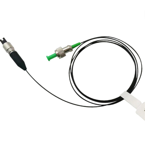
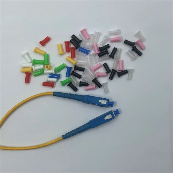
This guide provides a fully updated and industry-ready overview of LC fiber optics, explaining the origin and design of LC connectors, their key features, and the complete ecosystem of LC-based products used in modern networking. LC fiber connectors, as the most well-known representative of SFF (Small Form Factor) connector, are widely adopted in today's LAN and data center cabling. You may find LC connector has a strong family which includes but not limited to LC optical fiber connectors, LC fiber patch cables, LC fiber. Data centers will keep dominating optical module demand as AI and cloud drive revenue growth through 2030. Optical module demand is being pulled in two directions at once, faster bandwidth for dense networks and tighter constraints on power, security, and lead times. With global R&D projected to. LightCounting has proudly served our industry for 22 years with reports and services designed to help executives plan and run their businesses. We support decision-making based on our data, expert analysis and trusted forecasts. It covers LC connectors, LC patch cables, uniboot designs, armored. Optical Module Package Market was valued at 8942 million in 2024 and is projected to reach US$ 20220 million by 2032, at a CAGR of 12. With the surge in data traffic and the increasing demand for higher bandwidth, 100G optical modules have gained immense traction. These modules facilitate high-speed.
[PDF]

At its core, a fiber optic splitter relies on the principles of light reflection, refraction, and waveguiding to divide signals. Its design varies by type, but the underlying mechanism involves manipulating light to distribute its power across multiple output ports. A fiber optic splitter is a passive optical component that divides a single incoming optical signal into two or more outgoing signals, or combines multiple incoming signals into one. Their ability to efficiently manage optical signals makes them indispensable in various. This guide will demystify this pivotal passive device, exploring its types, working principles, and how it seamlessly integrates with optical transceivers to bring high-speed internet to your doorstep. 📄 What is an Optical Splitter? An Optical Splitter, also known as a beam splitter, is a passive. Fiber optic splitter is a passive optical device that includes multiple input and output ends. This principle allows a single input light beam to be split into N output light beams. The splitting can be achieved through two main methods: parallel beam splitting and beam divergence splitting. For example, an optical splitter.
[PDF]