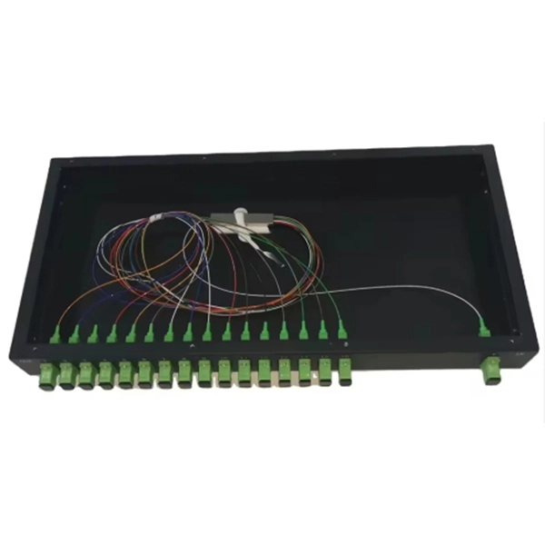
A PLC splitter is a passive optical device that divides one incoming optical signal from an input fiber into multiple output signals across several output fibers. PLC splitters utilize a planar lightwave circuit chip made of silica glass waveguides to distribute the optical power. PLC optical splitters (planar waveguide optical splitter) is a key component in optical fiber communication networks and is widely used in optical fiber distribution systems such as FTTH (fiber to the home) and PON (passive optical network). This passive yet sophisticated device utilizes integrated optics technology to split a single input signal into multiple. PLC splitter, also called Planar Waveguide Circuit splitter, is a device used to divide one or two light beams into multiple light beams uniformly or combine multiple light beams to one or two light beams. This helps share signals in fiber optic networks. Pick the split ratio that matches what you need. Lower ratios work for fewer users. Choose the connector type like SC, LC, or FC.
[PDF]
The centralized splitter approach typically uses a 1×32 splitter in an outside plant (OSP) enclosure, such as a fiber distribution terminal. The 1×32 splitter is directly connected via a single fiber to an OLT in the central office. They are typically installed in each optical network between the PON OLT (optical line terminal) and ONTs (optical network terminals) that the OLT serves. Generally, two kinds of fiber optic splitters are popular, which are FBT splitters and PLC splitters. The differences between the two have been. A fiber broadband provider typically determines and overall split ratio for the network, such as 1x32 or 1x64, and uses combinations of splitters to meet that ratio with each PON port. 1x32 splits were common in North America for G-PON architectures. As XGS-PON continues to be adopted, some service. This comprehensive guide explains how optical splitters work, what types are available, and how to select the optical splitter best buy or optical cable splitter best buy for your network deployment. What Is a Fiber Optic Splitter? A fiber optic splitter is a passive optical component designed to. Star couplers are used for their uniform splitting, while WDM splitters are used to split light beams of different wavelengths. Application Areas Fiber optic splitters are used in various areas, including active optical networks, passive optical networks, FTTX access networks, and measurement.
[PDF]
These beamsplitters are made by coating the hypotenuse of dual prisms with a partially reflecting material and joining them together using optical or epoxy cement. They eradicate the ghosting phenomenon because the transmitted beam is consistent with the incident light beam. A beam splitter or beamsplitter is an optical device that splits a beam of light into a transmitted and a reflected beam. It is a crucial part of many optical experimental and measurement systems, such as interferometers, also finding widespread application in fibre optic telecommunications. This division allows for the simultaneous analysis or utilization of the light's properties along two separate paths. These tools can split both laser and regular light. Image Credit: Shanghai Optics Most plate beamsplitters are. 📦 For purchasing, use the RP Photonics Buyer's Guide for beam splitters. It provides an expert-curated supplier directory, buyer-focused technical background information, and structured selection criteria to support professional procurement decisions. Beamsplitters are often classified according to their construction: cube or plate. Beam splitters are used to manipulate and control light, making them valuable devices in both classical and quantum optics. A beam splitter is capable of introducing phase shifts and quantum superpositions, making them a core component of quantum technologies such as quantum computing and Quantum.
[PDF]
Also, please take a look at the list of 18 fiber optic splitter manufacturers and their company rankings. YINGDA TECHNOLOGY LIMITED, 2. Shenzhen Spring Optical Communication Co. What Is a Fiber Optic. PPC Broadband offers a range of optical splitters designed for various applications, including indoor and outdoor use. Their expertise in fiber solutions for telecommunications ensures high-quality performance in connectivity technology. T&S Communications specializes in optical network. The global market for Optical Splitter was estimated to be worth US$ 698. 9 million in 2023 and is forecast to a readjusted size of US$ 1021. 5% during the forecast period 2024-2030 China is the largest producer of Optical Splitter, with a market share about 50%. Whether you're a homeowner upgrading your FTTH setup or a small business installing a new fiber network, knowing the best brands, their popular products, and pricing can help you make an informed decision. By comparing these factories, you'll discover the best quality and value. Dive in to find out which options can elevate your connectivity experience! Fiber Optic Splitters – Maxcom, Inc. Contract manufacturing services are also offered. Suitable for micro-electromechanical systems (MEMS). Distributor of fiberoptic equipment including splitters.
[PDF]
FBT splitters are more sensitive to fiber bending and environmental expansion, particularly under uneven thermal conditions. A beam splitter or beamsplitter is an optical device that splits a beam of light into a transmitted and a reflected beam. It is a crucial part of many optical experimental and measurement systems, such as interferometers, also finding widespread application in fibre optic telecommunications. a laser beam) into two (or sometimes more) beams, which may or may not have the same optical power (radiant flux). Different types of beam splitters exist, as described in the. Fiber optic splitters distribute optical power from one input fiber to multiple output fibers through either fused biconical taper (FBT) coupling or planar lightwave circuit (PLC) waveguide structures. Their performance depends on optical symmetry, waveguide integrity, and mechanical stability of. : The invention provides a light generating system (1000) comprising a first light generating device (110), a second light generating device (120), a luminescent material (200), a diffuser assembly (700), optical elements (500) comprising a first redirection optical element (1510), and a light exit. When splitting one incident light beam into two separate beams, beamsplitters are applied. Depending on the beam split based on intensity, wavelength, or polarization, its level of optical power on beam penetration differ. Just to mention few, these beamsplitter components are commonly required for.
[PDF]
At its core, a fiber optic splitter relies on the principles of light reflection, refraction, and waveguiding to divide signals. Its design varies by type, but the underlying mechanism involves manipulating light to distribute its power across multiple output ports. A fiber optic splitter is a passive optical component that divides a single incoming optical signal into two or more outgoing signals, or combines multiple incoming signals into one. Their ability to efficiently manage optical signals makes them indispensable in various. This guide will demystify this pivotal passive device, exploring its types, working principles, and how it seamlessly integrates with optical transceivers to bring high-speed internet to your doorstep. 📄 What is an Optical Splitter? An Optical Splitter, also known as a beam splitter, is a passive. Fiber optic splitter is a passive optical device that includes multiple input and output ends. This principle allows a single input light beam to be split into N output light beams. The splitting can be achieved through two main methods: parallel beam splitting and beam divergence splitting. For example, an optical splitter.
[PDF]
By dividing a single optical signal from a central Optical Line Terminal (OLT) into multiple outputs for Optical Network Terminals (ONTs) at users' homes, splitters eliminate the need for dedicated fibers to each residence—slashing infrastructure costs while scaling network reach. Understanding Fiber Optic Splitters: Principles, Parameters, Types, Applications, and Future Trends 1. Introduction Fiber optic splitters are integral components in the world of optical networks. They are devices that split an incident light beam into several light beams at certain splitting. The PLC optical splitter (Planar Lightwave Circuit splitter) is one of the most widely used passive components in modern optical communication systems. A fiber optic PLC splitter distributes a single optical signal into multiple outputs with high uniformity and low loss, making it ideal for. Optical splitter is a core passive device in FTTH system. Fiber splitters can effectively split optical signals into. Fiber optic splitters are essential passive devices in modern optical communication systems, enabling the division of a single light signal into multiple outputs or combining multiple signals into one. It is a crucial part of many optical experimental and measurement systems, such as interferometers, also finding widespread application in fibre optic telecommunications.
[PDF]
A PLC Splitter takes one optical signal and splits it into many outputs. This helps share signals in fiber optic networks. Pick the split ratio that matches what you need. Lower ratios work for fewer users. Choose the connector type like SC, LC, or FC. This. The optical splitter is an important passive device in the optical fiber link. It generally has one or two input ends and many outputs end for laser signal distribution. This article will explain the. Planar Lightwave Circuit (PLC) splitters play a vital role in modern fiber optic communication networks by enabling the efficient distribution of high-speed optical signals. It is one of the core components in Passive Optical Networks (PON) and is widely used in FTTx deployments, where a single fiber connection. This video provides a step-by-step guide on how to efficiently install optical splitter into a fiber terminal box, demonstrating a professional and reliable deployment for optical distribution network solution ( https://www. com/c/optical-distribu. more This video provides a step-by-step.
[PDF]
XGS-PON is a 10 Gbps symmetric passive optical network (X=10, S=symmetric). Optical fiber's greater transmission capacity and speed deliver upstream and downstream (symmetric) speeds of up to 10 Gbit/s (gigabits per second) on the road to connecting users in the last. 10G-PON (also known as XG-PON or G. 987) is a 2010 computer networking standard for data links, capable of delivering shared Internet access rates up to 10 Gbit/s (gigabits per second) over optical fibre. This is the ITU-T 's next-generation standard following on from GPON or gigabit-capable PON. It is commonly used to implement the link to the customer (the last kilometre, or last mile) of fibre-to-the-premises (FTTP) services, using a. Short on Ethernet ports and looking to connect an extra device or two to your wired network setup? You're likely to encounter two options: an Ethernet splitter, and an Ethernet switch. Here's why you should choose the switch every time. What Is an Ethernet Splitter? An Ethernet splitter is a simple. Recommendation ITU-T G. 1 describes a flexible optical fibre access network capable of supporting the bandwidth requirements of business and residential services and covers systems with nominal line rates of 2. 4 Gbit/s in the downstream direction and 1. 984 G-PON and ITU-T G. 9807 XGS-PON wavelengths to coexist within the same single mode fiber cabling and across the same passive optical distribution splitters. This means that users can.
[PDF]
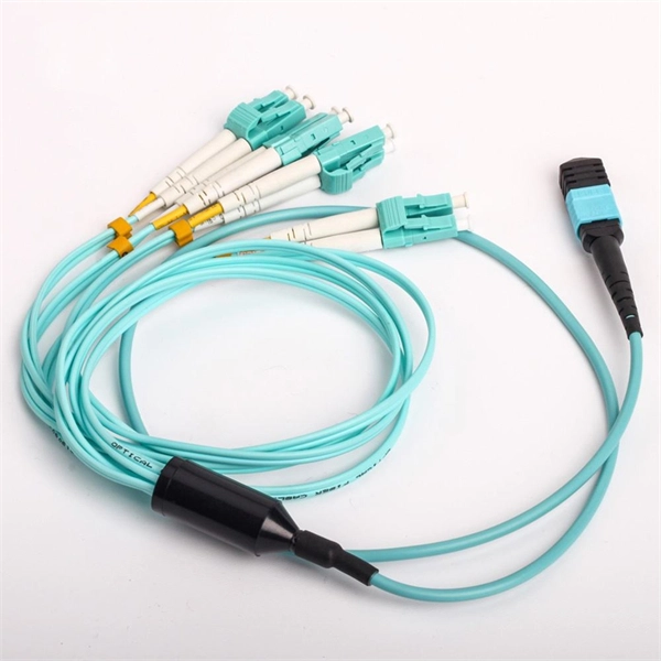
The SFP optical module is a standardized, modular assembly designed to be quickly installed or removed from a device's port without requiring the device to be powered down. This key feature—being hot-pluggable —is essential for simplifying network maintenance and minimizing downtime. SFP (Small Form-factor Pluggable) is a compact, hot-pluggable network interface module used to connect network devices (switches, routers, firewalls) to fiber optic or copper cables. It converts electrical signals into optical (or copper) signals and vice versa. An SFP transceiver acts as a compact, hot-swappable optical transceiver that. An SFP switch uses Small Form-Factor Pluggable (SFP) modules to form a network switch for high-speed connectivity between devices. These interchangeable modules support various media types, including copper or fiber-optic cables, providing flexible networking options based on specific requirements.
[PDF]
The optical module is the foundation of optical communication that provides photoelectric conversion (see Figure 2). The photoelectric conversion efficiency of optical modules is crucial, and it directly affects the quality and performance of optical communications. From the technical level, HISILICON makes improvements. These two products are part of the LIGHTPASS ® Series active optical modules expected to be used for optical interconnection applications and IOWN* structures used for data centers and other uses. Demo kits for evaluating these products will be available from September 2023, and mass production is. Microwave photonics technology (MWP), which has been applied to various radar, Telcom, Electronic Warfare systems, is now facing more and more challenging development trend of miniaturization and modular array for increasing node counts and system complexity. In the context of data communication, it involves transforming data into light pulses for transmission through optical fibers and converting received light signals back into electrical. The optical module is the key device in all the links of this circulation process (see Figure 1). Two modules are used in pairs. The radio-frequency signal.
[PDF]
BARCELONA, Spain, March 6, 2025 /PRNewswire/ -- At the Mobile World Congress 2025 (MWC 2025), Huawei launched the StarryLink optical modules, designed to enhance network experiences with "3S" quality (Spanning, Stable, Secure). This announcement occurred during the data center session titled. Very little is written about Huawei's optical DWDM technology, but that doesn't mean the company hasn't made some big waves in the industry. We had the chance to sit down with the Huawei optical team, led by Gavin Gu, at MWC 2026 to learn about their latest coherent DWDM technology.
[PDF]
Frequent status changes from up to down or vice versa in the ports logged by the switch port syslog indicates a port flap. On a big industrial plant we've replaced an old HP switch with a brand new couple of C2960x switches in stack configuration and ever since then, every 6/8 hours or so, the two fiber optics links of switch #2 go down at once. These are connected to a ring of 3 similar other access switches, that. EX4650 2-switch virtual chassis, running version 19. 2, optic p/n 740-031981 (SFP+-10G-LR) is plugged into port xe-0/0/10 and connected to an ISP via single mode fiber. Nothing special is configured on the port, it is running at 10G speed, show interfaces diagnostics optics shows that it's. This article describes steps to diagnose the Continuous port flapping on a FortiSwitch. Verify Cable Connection: Ensure the cable is properly connected between the switch port and the end device. Run the command below on FortiSwitch multiple times and check the. Real head scratcher this morning that I'm hoping someone can help me with! The port on our core switch (HP A5500) that our Smoothwall box is connected to keeps going up and down. Port flapping, also known as link flapping, causes a switch port's state to fluctuate between up and down within concise periods of time. This instability caused by flapping ports affects network connectivity. Port flapping is a common network issue that can disrupt communication between devices and degrade overall network performance.
[PDF]
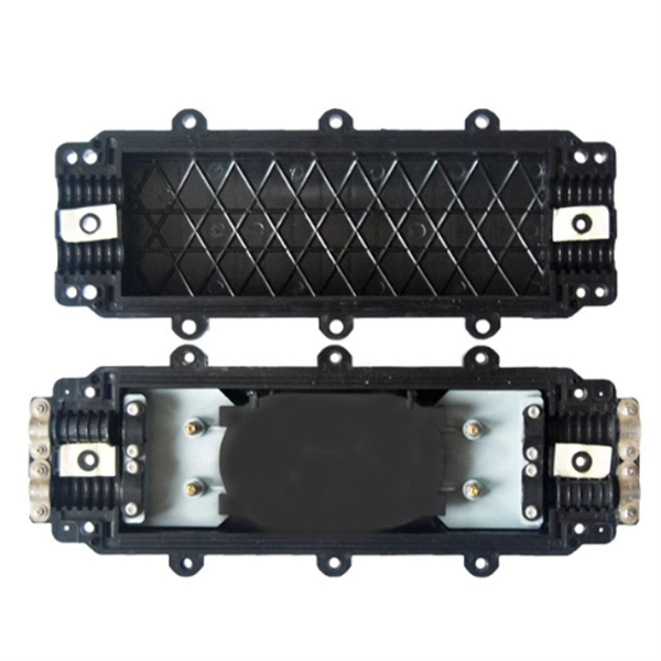
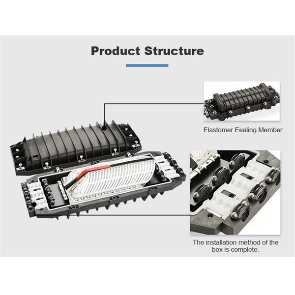
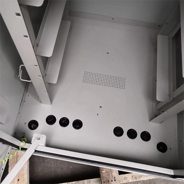
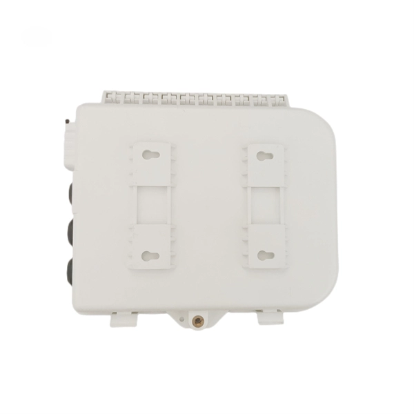
OPGW cable joint box installation involves several key stages: selecting the appropriate location, preparing both the cable and the joint box, splicing fibers, and sealing the joint box properly. Adhering to these steps ensures optimal performance and longevity of the telecommunications system. Optical fiber junction boxes are essential components in outdoor optical fiber cable installations. In this article, we will discuss the necessary steps and best practices. The Indoor/Outdoor Splice Box is a wall-mounted, indoor/outdoor fiber splice enclosure for centralized splice-only applications. These boxes are well suited as optical cable splice collection points for MDU (Multi-Dwelling Unit) residential fiber network applications, MTU (Multi-Tenant Unit). The installation of an optical cable junction box is crucial in ensuring the integrity and performance of optical networks. As we enter 2024, adhering to best practices not only enhances system reliability but also mitigates potential issues that can affect customer experiences. Installing a fiber optic splice closure efficiently and effectively requires attention to detail and. AFL's SB01 splice enclosure provides protection from all types of elements. From weather to bullets, the iron and steel construction requires no additional protective covering. Furnished with four plugged cable ports (2 aluminum and 2 plastic) for either All-Dielectric Self-Supporting (ADSS) or.
[PDF]
Lasers, modulators, and photodiodes form the core architecture of optical transceivers, enabling light-speed communication across global networks. Lasers generate the optical carrier. Modulators encode digital information. An optical transmitter is a crucial device used in fiber optic communication systems. Its primary function is to convert electrical signals into optical signals It involves modulating electronic system data and transforming it into light pulses using a laser or LED, and sending the pulses through. The optical transmitter and the optical receiver are the core components that enable this process, forming the electronic-to-optical and optical-to-electronic gateways necessary for modern, high-capacity data transmission. It takes data from an electronic system, uses a laser or LED to modulate that data into pulses of light, and then sends those pulses down the fiber. Together, lasers, modulators, and. At the core of a fiber optic system is the optical fiber – a flexible, transparent strand of glass, thinner than a human hair. Optical fiber is formed by drawing glass or plastic to a diameter slightly thicker than that of a. What are the main elements of an optical transmitter? Data decoder/demodulator, electrical interface, detector, optical interface.
[PDF]