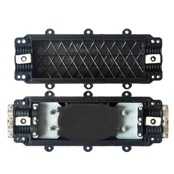
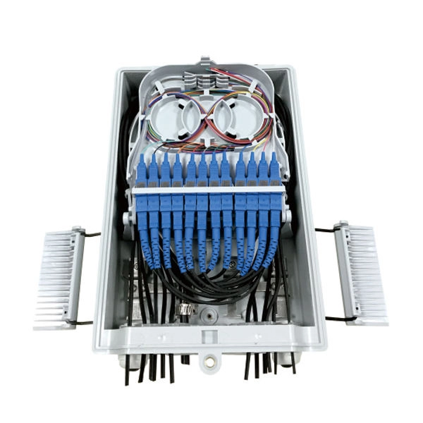
OPGW cable joint box installation involves several key stages: selecting the appropriate location, preparing both the cable and the joint box, splicing fibers, and sealing the joint box properly. Adhering to these steps ensures optimal performance and longevity of the telecommunications system. Optical fiber junction boxes are essential components in outdoor optical fiber cable installations. In this article, we will discuss the necessary steps and best practices. The Indoor/Outdoor Splice Box is a wall-mounted, indoor/outdoor fiber splice enclosure for centralized splice-only applications. These boxes are well suited as optical cable splice collection points for MDU (Multi-Dwelling Unit) residential fiber network applications, MTU (Multi-Tenant Unit). The installation of an optical cable junction box is crucial in ensuring the integrity and performance of optical networks. As we enter 2024, adhering to best practices not only enhances system reliability but also mitigates potential issues that can affect customer experiences. Installing a fiber optic splice closure efficiently and effectively requires attention to detail and. AFL's SB01 splice enclosure provides protection from all types of elements. From weather to bullets, the iron and steel construction requires no additional protective covering. Furnished with four plugged cable ports (2 aluminum and 2 plastic) for either All-Dielectric Self-Supporting (ADSS) or.
[PDF]
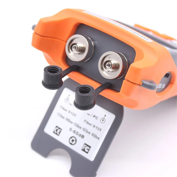
The optical budget refers to the maximum allowable signal loss between the transmitter and receiver in a fiber-optic link. It ensures that the received signal is strong enough for the equipment to process data without errors. Calculated in decibels (dB), it is the difference between the. After measuring the loss of a fiber link, you now have to determine if that fiber link loss is acceptable or not. You can either compare this loss value to the application requirement or calculate the expected loss based on how many connectors and splices are in the link along with the length of. Optical module channel loss resistance refers to the maximum optical path attenuation that an optical transceiver module can tolerate while still maintaining compliant signal integrity, error performance, and link stability. There are many reasons for optical fiber loss, such as optical fiber material's absorption/scattering of light energy, bending.
[PDF]
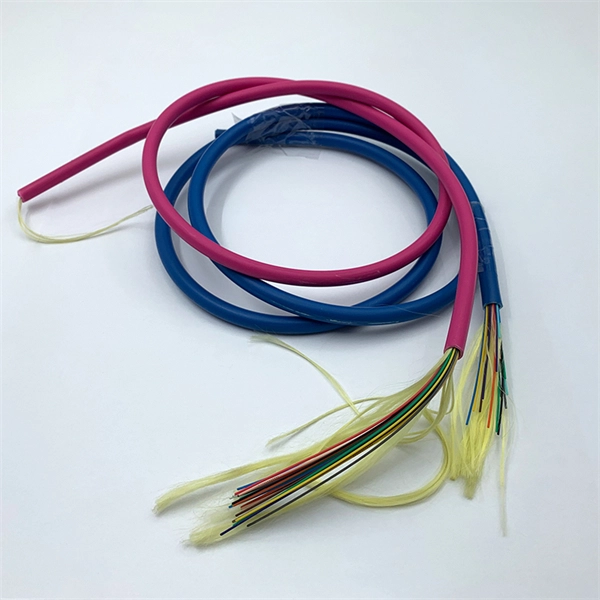
A 4-core fiber optic cable is a type of cable that contains four individual optical fibers within a single protective jacket. These fibers are used to transmit data as light signals, offering high-speed data transfer capabilities over long distances with minimal loss. This guide covers everything you need to know about 4 core fiber, including its internal structure, TIA standard color coding, and how to choose the right type. They are used to connect final user to FTTH or GPON line. Jera is a direct manufacturer who supply a wide range product for. This cable can be used for LAN and WAN backbones, telecom access lines, fibre to business and fibre to the building or the homme connections. It is equally suited for installation in ducts and on trays. This cable features a 0. 15mm corrugated steel armour which makes it rodent proof. OM3 and higher. A TOSLINK optical fiber cable with a clear jacket. What is a 4 Core Optical Cable? A 4 Core Optical Cable is a fiber optic cable that contains four individual optical fibers within a single. Unlike copper wires, which are limited by lower data transmission speeds, shorter transmission distances, and higher susceptibility to electromagnetic interference, fiber optic cables offer unparalleled performance and can cover much greater distances without bumping up against signal degradation.
[PDF]
ExxonMobil Guyana's fibre optic cable has landed, Guyana Vice President Bharrat Jagdeo said during a December 28 press conference. Ongoing construction of an offshore command centre at Ogle, East Coast Demerara, is expected to conclude this year. Prime Minister Bridgadier (Ret'd) Mark Phillips commissioned a new multi-billion-dollar direct submarine fibre-optic cable, marking a historic moment for the region and closing the long-standing digital gap between the coastland and the hinterland. The milestone ushers in gigabit-speed. ENet has completed a transformative multibillion dollar telecommunications project, landing the first ever direct submarine fiber‑optic cable to Bartica. This pioneering investment brings state-of-the-art fiber connectivity and 5G mobile service to the hinterland town, connecting Bartica directly. – PM Phillips says no region will be left behind in Guyana's digital transformation IN a ground-breaking development for Guyana's hinterland connectivity, Prime Minister Brigadier (Ret'd) Mark Phillips on Wednesday hailed the commissioning of the first-ever direct submarine fibre-optic cable to. Prime Minister Brigadier (Ret'd) the Honourable Mark Phillips hailed the commissioning of the first direct submarine fibre-optic cable to Bartica as a transformative development that brings the hinterland town in line with the capital city's digital capabilities. Speaking at the commissioning.
[PDF]
This paper aims to study the design, simulation, and optimization of low-loss Y-branch passive optical splitters up to 64 output ports for telecommunication applications. For a waveguide channel profile, the standard material silica-on-silicon is used. Two important technologies for optical layer monitoring are Optical Performance Monitoring (OPM) and Optical Power Detection (OPD). Although they aim to maintain network health, they differ significantly in scope, technique, and deployment. This article delves into these differences, equipping. Optical Performance Monitoring (OPM) is considered a necessity over an optical network to enable sensibility of traffic line status and attain outstanding Quality-of-Service (QoS). The Y-splitters are designed and simulated at. Passive optical networks (PONs) are the network architecture of choice for residential fiber deployments. A PON is designed specifically to be cost-effective for delivering high data-rates to large customer populations. signals and various components of OPM functionalities are indispensable robust network operation and plays a key role flexibility and improve overall. Optical performance monitoring (OPM) is used for managing high capacity dense wavelength-division multiplexing (DWDM) optical transmission and switching systems in Next Generation Networks (NGN). OPM involves assessing the quality of data channel by measuring its optical characteristics without.
[PDF]
Fiber optic "cable" refers to the complete assembly of fibers, other internal parts like buffer tubes, ripcords, stiffeners, strength members all included inside an outer protective covering called the jacket. Cable provides protection for the optical fiber or fibers within it appropriate for the environment in which it is installed. You will also learn how different aspects of the product can affect budget and design. ■ The Five Key Parts of a Fiber Optic Cable A fiber optic cable. A fiber optic cable consists of five basic components: the core, the cladding, the coating, the strengthening fibers, and the cable jacket. When searching for a fiber optic cable, we need to pay attention not only to the connectors, such as SC to ST fiber cable, LC to SC fiber patch cable, or SC to. A TOSLINK optical fiber cable with a clear jacket. These cables are used mainly for digital audio connections between devices. This advanced cabling solution allows fast, secure data transfer and telecom over long distances. Understanding the components within a fiber optic cable enables. While fiber optic cable itself is cheaper than an equivalent length of copper cable, fiber optic cable connectors and the equipment needed to install them have typically been more expensive than their copper counterparts.
[PDF]
In this paper, a thermally tuned silicon-based three-channel reconfigurable multimode interference (MMI) optical power splitter with four optimized thermal isolations is proposed. Specific and flexible reconfig-urable functions (1, , and MMI splitters) can be achieved by. Abstract: We demonstrate integrated photonic circuits for quantum devices using sputtered polycrystalline aluminum nitride (AlN) on insulator. 56(1), 017106 (2017), doi: 10. The two most common types of splitters offered are polarizing beam splitters and polarization maintaining beam splitters. Their operating principles are as follows: Polarization Maintaining. optical transimission & integration needs of any system. MEISU specializes in precise custom fiber array sub-assemblies and PM fiber optical components and assemblies for different areas like integrated optics, sensoring, healthcare, spectroscopy, etc., 50/50 FBS, can be used as the frequency-mode Hadamard gate for frequency-encoded photonic qubits. Quantum cryptography is the key point of quantum communication. In classical cryptography classical bits are used but in quantum cryptography quantum bits (qubit) are used. Quantum communication sends the information through some channels such that, optical fibre, satellite etc.
[PDF]
BARCELONA, Spain, March 6, 2025 /PRNewswire/ -- At the Mobile World Congress 2025 (MWC 2025), Huawei launched the StarryLink optical modules, designed to enhance network experiences with "3S" quality (Spanning, Stable, Secure). This announcement occurred during the data center session titled. Very little is written about Huawei's optical DWDM technology, but that doesn't mean the company hasn't made some big waves in the industry. We had the chance to sit down with the Huawei optical team, led by Gavin Gu, at MWC 2026 to learn about their latest coherent DWDM technology.
[PDF]
This Technical Brochure describes the induction phenomena (inductive, capacitive and conductive) that can lead to presence of voltage and currents on disconnected cable systems. The optical fiber composite overhead ground wire (OPGW) has been widely used in power transmission lines. Methods of calculation to evaluate those values and touch voltages are detailed and analysed, associated with various. working on cables u al, photocopying, recording or otherwise, without the prior written or use by members of the Energy Networks Association to take account of the conditions which apply to them. Advice should. Literature review: An in-depth literature review covering the modelling and calculations of the conditions relating to faults caused by interactions between fibre optic cables and power cores in submarine cables. Examples of electrically conductive installations where induced voltage may occur could be: • Overhead lines or cables out of opera- tion •.
[PDF]
In this Cisco Tech Talk, learn how to view the optical module status on a Cisco switch using the Command Line Interface (CLI). This video demonstrates how to access the optical module status, check for any issues, and monitor the health of your network's optical components. Learn. When optical modules operate on a switch, it is usually necessary to read the module's internal information to understand its working status—such as connection status and real-time metrics like optical power and temperature. Additionally, identifying module information helps detect coding. This chapter describes how to configure the Optical Amplifier Module and Protection Switching Module (PSM). When you plan to replace a configured optical module with a different type of optical module, you must clear the configurations of the old module before you install the new module. By checking module health, compatibility, and digital diagnostics, you can quickly confirm correct installation, detect optical problems, and maintain accurate hardware. Small Form-factor Pluggable modules (SFP module) are the workhorses of modern network connectivity, enabling flexible fiber optic or copper links between switches, routers, firewalls, and servers. Whether you're upgrading bandwidth, replacing a faulty unit, or reconfiguring your topology, knowing.
[PDF]
Total number of cores = Number of branches × Number of cores per branch If there are no branches, the number of branches equals one. For example, an MTP®-8 trunk cable with four branches and eight cores per branch has a total of 32 cores (4 × 8 = 32). For example, if you have three optical fiber access switches, you need to have three cores. (actually use a four core optical cable) This is because apart from one-core optical fiber, there are basically no optical cables with an odd number of cores, such as three-core, five-core, etc. It is worth. Fiber cores are the heart of fiber optic cables, transmitting light signals that carry data. Made from either high-quality glass or plastic, the core plays a critical role in determining the cable's performance. The total number of cores for a 1pc fiber patch cable is calculated as the number of. One key factor is the number of cores, which impacts how much data you can transmit. Single-mode: A. Common fiber cores include 1 core, 2 cores, 6 cores, 8 cores, etc., and there are many types. This article will focus on the number of fiber cores, introducing their respective characteristics and usage scenarios. Of course, this is a general situation, and it can be considered as follows: 1.
[PDF]
Calibration & Repair services in Ireland. 5 day turn around with competitive pricing! View full electrical test and measurement equipment list here. is an independent calibration laboratory focused on meeting the total quality requirements of industry. Proper calibration of today's sophisticated test and measurement equipment is essential for preserving measurement accuracy, complying with international standards. Parameters covered include; Temperature, Humidity, Dewpoint, Various Gases, Pressure, Electrical, Weights & Scales, Analytical and some Specialist calibrations. Calibration is performed using the very latest Calibration Equipment/Standards & Calibration/Asset Management Software. Fast Efficient. PTM Calibration offers a wide range of services that complement our core business. We aim to be your one stop shop for all your calibration, test & measurement needs. From major blue chip companies & medium enterprises to small companies and sole traders. Including: aerospace, pharmaceuticals. OptiCal Sciences are an authorised service centre with service, repair and calibration experience and procedures for an extensive variety of models from a wide range of manufacturers.
[PDF]

Venezuelan and Iranian authorities announced this weekend the signing of an agreement to build a fiber optic factory in the South American country, more specifically in La Guaira, a State just 30 kilometers north of Caracas and home to the country's gateway Simón Bolívar Airport. Photo: La Guaira EEZ Home La Guaira The first production line for manufacturing cables arrives in La Guaira. The rest of the machinery to put the plant. The Islamic Republic of Iran has extended its export of advanced technology to the heart of Latin America with the establishment of a fiber optic plant in Venezuela. This strategic move is part of Iran's broader objective to expand its technology diplomacy and showcase its advanced technical capabilities on an international scale. The. The new plant, named Venefibra, represents an effort in the pursuit of technological sovereignty and economic diversification. Photograph: Radio Miraflores. Guacamaya, July 10, 2025. Venezuela has received a significant boost to its.
[PDF]
An optical module is a typically hot-pluggable optical transceiver used in high-bandwidth data communications applications. Optical modules typically have an electrical interface on the side that connects to the inside of the system and an optical interface on the side that connects to the outside world through a fiber optic cable. The form factor and electrical interface are often specified by an int. Electrical Interface TypesThere have been multiple variants of the electrical interface of optical modules that have been used over the years. The earliest forms of optical modules had an analog electrical interface. In the transmit dir. Many different forms of optical modulation and multiplexing have been employed in optical modules. The most common modulation technique historically has been or NRZ.
[PDF]
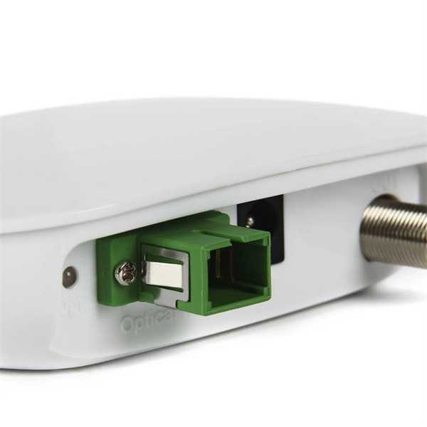
The SFP optical module is a standardized, modular assembly designed to be quickly installed or removed from a device's port without requiring the device to be powered down. This key feature—being hot-pluggable —is essential for simplifying network maintenance and minimizing downtime. SFP (Small Form-factor Pluggable) is a compact, hot-pluggable network interface module used to connect network devices (switches, routers, firewalls) to fiber optic or copper cables. It converts electrical signals into optical (or copper) signals and vice versa. An SFP transceiver acts as a compact, hot-swappable optical transceiver that. An SFP switch uses Small Form-Factor Pluggable (SFP) modules to form a network switch for high-speed connectivity between devices. These interchangeable modules support various media types, including copper or fiber-optic cables, providing flexible networking options based on specific requirements.
[PDF]