In this guide, you will find a chronological description of the fusion splicing process, the principal technical standards, and answers to the real-life questions network engineers and procurement teams may have. Splicing fiber optic cable is an extremely important phase for making dependable, high-speed communication infrastructures. Regardless of the type of fiber network you're deploying, be it for telecom, enterprise data centers, or smart city infrastructure, fusion splicing provides the benefits of. This is where fiber optic cable splicing—the process of creating a permanent, high-performance join between two fiber ends—becomes critical. For network managers and technicians, a poor splice can lead to significant signal degradation, network downtime, and costly troubleshooting. At Turn-Key. So in essence, fiber optic splicing is a process used to join two separate fiber optic cables together. There are numerous use cases for fiber optic splicing. Ensure Your Splicing Tools are Clean – #2. And tools used for fiber fusion: fusion splicer; fiber cleaver; cable stripper; fiber optic stripper; alcohol;. Splicing with fusion splicers, in particular, has become an attractive method to quickly and easily connect fiber optic fibers. Using the proper tool allows to connect the individual fibers of fiber optic cables extremely professionally. However, there are a few points to keep in mind during the.
[PDF]
The number of optical cores in an optical fiber is the total number of equipment interfaces multiplied by 2, plus 10% to 20% of the spare quantity, and if the communication mode of the equipment has serial communication and equipment multiplexing, you can reduce the number of cores. The number of. There are several ways to know the number of multi-spliced cores. For example, 12 core fibers, 12*2=24 cores, 12 cores at the beginning and 12 cores at the end; 2. If. This article will walk you through the basics of fiber optic cores and provide practical guidance for selecting the suitable fiber optic cable to meet your networking needs. Fiber cores are the heart of fiber optic cables, transmitting light signals that carry data. Made from either high-quality. By adopting the TIA/EIA‑598C standard, you gain a universal “language” of colors that speeds identification, reduces miswiring, and enhances safety across cable jackets, connectors, buffer tubes, and splice trays. Error Reduction: A standardized palette prevents costly mis‑splices and. The number of cores is the number of glass fibers contained in each fiber. First of all, clearly know the number of wiring points in this layer, calculate the number of switches, and whether the connections.
[PDF]
Even when splicing identical fibers together, if they are not perfectly aligned, optical power will be lost and attenuation across the splice will exist. The performance of a fiber optic splice is determined by a number of factors, including the quality of the fiber, the cleanliness of the splice, and the techniques used to make the splice. Intrinsic factors, such as the refractive index of the fiber, are those that are inherent to the fiber itself. Fiber optic cable splicing is the process of joining two fibers end-to-end to create a continuous optical path. In PON and FTTx networks (e., FTTH, FTTP, FTTM), splicing is essential for extending cables, repairing breaks, or connecting backbone and distribution lines. To protect these vulnerable. Fiber loss, also called fiber optic attenuation or attenuation loss, refers to the loss of signal between input and output. Losses can be introduced by various means such as intrinsic material absorption, scattering, bending, connector loss and more. The absorption is caused by the absorption of the light and conversion to heat by molecules in the glass. Primary absorbers are residual OH+ and dopants used to modify the refractive index of the glass. Unlike using connectors, which are designed for frequent connection and disconnection at patch panels, splicing creates a permanent, stable joint with minimal light loss. This process is fundamental to building and.
[PDF]
A fusion splicer is a specialized device used to join two optical fibers end-to-end through the process of fusion. By aligning the fibers precisely and applying a controlled electric arc, the fusion splicer melts the ends of the fibers, creating a single, continuous fiber. Fusion splicers are essential for creating low-loss, high-performance fiber optic connections in telecom, FTTH, and data center applications. The best splicers offer core alignment, fast splice times, durable designs, and smart features like cloud syncing and automated calibration. This process minimizes. Fiber splicing is the process of permanently joining two fibers together. Unlike fiber connectors, which are designed for easy reconfiguration on cross-connect or patch panels. There are two types of fiber splicing – mechanical splicing and fusion splicing. It is the technique that has the least insertion loss and almost no back reflection, hence ensuring strong connections over a long period. Fiber optic splicers are.
[PDF]
This guide reveals the secrets to fusion splicing with little fluff—just proven, straightforward techniques refined from years of work in the field. In this guide, you will find a chronological description of the fusion splicing process, the principal technical standards, and answers to the real-life questions network engineers and procurement teams may have. The guide provides the complete workflow, covering safety precautions, tool selection, fiber preparation, fusion operation, quality control, and. Summary: Fiber color codes, defined by the TIA-598-C standard, help technicians quickly identify individual fibers, buffer tubes, and connectors in multi-strand cables. Using proper color coding makes installation easier, speeds up troubleshooting, reduces downtime, and supports future network. When a tech opens a fiber optic cable to prepare it for splicing, they will find a colorful bundle of buffer tubes as on this armored cable. The colors of the buffer tubes and likewise the fibers in the tubes provide the identification the tech needs to complete the splicing of the fibers as the. Fusion splicing is the bedrock of high-performance fiber optic networks, enabling seamless signal transmission through permanent, low-loss fiber joins. By adopting the TIA/EIA‑598C standard, you gain a universal “language” of colors that speeds identification, reduces miswiring, and enhances safety.
[PDF]
Merriam-Webster defines it as a “humorous internet slang term” meaning “to outclass,” typically used to describe someone as far more attractive than another. While forecasts are more uncertain in the spring and the strength of the upcoming warming phase remains very uncertain, NOAA is forecasting a 1-in-3 chance of a super El Niño by October, November and December. A super El Niño is defined as water temperatures being at least 2°C above average over. At its core, “mogging” is about comparison: when one person significantly outshines another in looks, physique, or even life status. Being “mogged,” on the other hand, means being on the losing end of that comparison. However, it does have some meaning depending on how it is used. Teens will often say 67 while making a hand gesture as if they're weighing things on a balance. Saying 67 with that hand gesture can mean “so-so” or “about”, but the emote can. While “SYBAU” sounds like the name of a luxury car or some new technology software, it's far from that. ICYMI, “SYBAU” is a Gen Z internet slang term that's popping up all over social media. Whether it's used in the caption of a TikTok, plastered in the comment section, or sent to you by your.
[PDF]
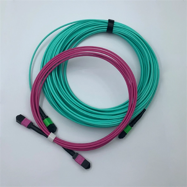
Total number of cores = Number of branches × Number of cores per branch If there are no branches, the number of branches equals one. For example, an MTP®-8 trunk cable with four branches and eight cores per branch has a total of 32 cores (4 × 8 = 32). For example, if you have three optical fiber access switches, you need to have three cores. (actually use a four core optical cable) This is because apart from one-core optical fiber, there are basically no optical cables with an odd number of cores, such as three-core, five-core, etc. It is worth. Fiber cores are the heart of fiber optic cables, transmitting light signals that carry data. Made from either high-quality glass or plastic, the core plays a critical role in determining the cable's performance. The total number of cores for a 1pc fiber patch cable is calculated as the number of. One key factor is the number of cores, which impacts how much data you can transmit. Single-mode: A. Common fiber cores include 1 core, 2 cores, 6 cores, 8 cores, etc., and there are many types. This article will focus on the number of fiber cores, introducing their respective characteristics and usage scenarios. Of course, this is a general situation, and it can be considered as follows: 1.
[PDF]
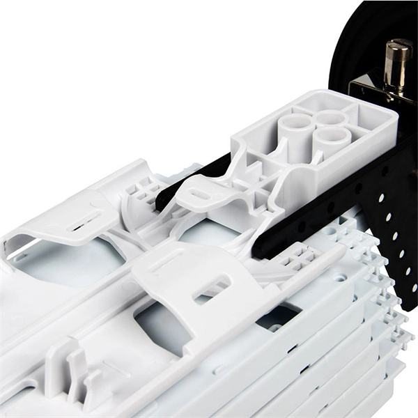
This guide delves into the structure and working principle of fiber optic connectors and outlines the critical steps for creating a successful connection. Proper connection of fiber optic cables is essential to harness these benefits fully, as even minor errors can lead to significant performance issues like signal loss. This article will guide you through the necessary tools, materials, and methods on how to connect fiber optic cables effectively. The FCR-1000 series cable reels are designed to fit Princetel's standard FORJs and slip rings. The rotary joints are protected inside the drum for durability and seamless deployment of single or multi-channel fiber optic and/or electrical cable with uninterrupted optical and/or electrical signal. Fiber optic connectors play an essential role in the realm of optical communication, enabling seamless connections between fiber optic cables. This guide will walk you through the complete process of connecting fiber optic cable. Before connecting any fiber cable, you need to assemble the proper preparation tools: With the right tools in hand, follow these key steps to achieve reliable fiber connections: 1. Strip and Clean Fiber Ends. In this video, we'll guide you through preparing and terminating fiber optic cables using SimplyFiber products, known for their high quality, ease of use, and reliability. more Audio tracks for some languages were automatically generated. Learn more In this video, we'll guide you through.
[PDF]
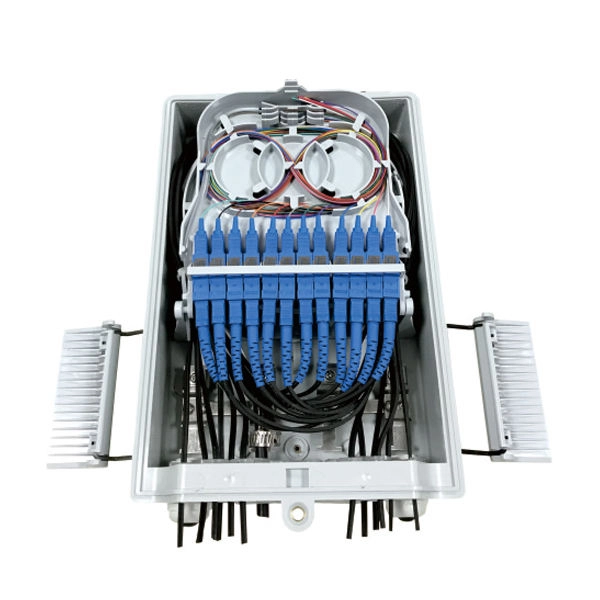
Fiber optic connectors join optical fibers, allowing for quick connection and disconnection without significant signal loss. They are essential in establishing temporary or semi-permanent links in fiber optic networks. Executive Summary: A fiber optic pigtail is one of the most commonly specified yet least understood components in structured cabling. Get the wrong connector type, the wrong polish, or skip proper fusion splicing technique—and you're looking at elevated signal loss, increased back reflection, and a. Fiber optic joints or terminations - where cables are terminated - are made two ways: 1) connectors that mate two fibers to create a temporary joint and/or connect the fiber to a piece of network gear (left) or 2) splices which create a permanent joint between the two fibers (right). These terminations must be of the right style, installed in a. There are three main components of a fiber optic connector: the ferrule, the connector, and the coupling mechanism. Epoxy or Polish Fiber Connectors are very traditional and widely used connectors. Proper termination is essential for ensuring optimal performance, reducing signal loss, and maintaining the durability of the connection. There are two primary.
[PDF]
ExxonMobil Guyana's fibre optic cable has landed, Guyana Vice President Bharrat Jagdeo said during a December 28 press conference. Ongoing construction of an offshore command centre at Ogle, East Coast Demerara, is expected to conclude this year. Prime Minister Bridgadier (Ret'd) Mark Phillips commissioned a new multi-billion-dollar direct submarine fibre-optic cable, marking a historic moment for the region and closing the long-standing digital gap between the coastland and the hinterland. The milestone ushers in gigabit-speed. ENet has completed a transformative multibillion dollar telecommunications project, landing the first ever direct submarine fiber‑optic cable to Bartica. This pioneering investment brings state-of-the-art fiber connectivity and 5G mobile service to the hinterland town, connecting Bartica directly. – PM Phillips says no region will be left behind in Guyana's digital transformation IN a ground-breaking development for Guyana's hinterland connectivity, Prime Minister Brigadier (Ret'd) Mark Phillips on Wednesday hailed the commissioning of the first-ever direct submarine fibre-optic cable to. Prime Minister Brigadier (Ret'd) the Honourable Mark Phillips hailed the commissioning of the first direct submarine fibre-optic cable to Bartica as a transformative development that brings the hinterland town in line with the capital city's digital capabilities. Speaking at the commissioning.
[PDF]
Several different designs are used to create birefringence in a fiber. The fiber may be geometrically asymmetric or have a refractive index profile which is asymmetric such as the design using an elliptical as shown in the diagram. Alternatively, permanently induced in the fiber will produce ; this may be accomplished using rods of another material included within the cladding. Several dif.
[PDF]
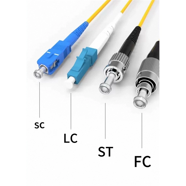
Fiber optic "cable" refers to the complete assembly of fibers, other internal parts like buffer tubes, ripcords, stiffeners, strength members all included inside an outer protective covering called the jacket. Cable provides protection for the optical fiber or fibers within it appropriate for the environment in which it is installed. You will also learn how different aspects of the product can affect budget and design. ■ The Five Key Parts of a Fiber Optic Cable A fiber optic cable. A fiber optic cable consists of five basic components: the core, the cladding, the coating, the strengthening fibers, and the cable jacket. When searching for a fiber optic cable, we need to pay attention not only to the connectors, such as SC to ST fiber cable, LC to SC fiber patch cable, or SC to. A TOSLINK optical fiber cable with a clear jacket. These cables are used mainly for digital audio connections between devices. This advanced cabling solution allows fast, secure data transfer and telecom over long distances. Understanding the components within a fiber optic cable enables. While fiber optic cable itself is cheaper than an equivalent length of copper cable, fiber optic cable connectors and the equipment needed to install them have typically been more expensive than their copper counterparts.
[PDF]
SAXONBURG, PA, October 28, 2025 (GLOBE NEWSWIRE) – Coherent Corp. (NYSE: COHR), a global leader in photonics, today announces the launch of its next generation polarization-maintaining optical fiber, engineered to deliver superior performance and reliability for the. SAXONBURG, PA, October 28, 2025 (GLOBE NEWSWIRE) – Coherent Corp. This advanced fiber is designed to. At the heart of this advanced technology lies Polarization maintaining fibe r —a specialized optical fiber engineered to preserve the polarization state of light, a capability that standard single-mode fibers lack. As coherent communications demand precise control over light's polarization to. Polarization maintaining (PM), all-fiber amplifiers offer the benefits of alignment free and environmentally stable operation. To achieve high output powers, particularly in pulsed operation, it is necessary to balance the need to reduce deleterious nonlinear effects, often through the use of large. tion assisted by digital signal processing (DSP). The objective of this tutorial chapter is to briefly review the operating principles of state-of-the-art ong-haul coherent optical communications systems. Due to limitations in space, it focuses mainly on coherent optical systems usin major.
[PDF]
This comprehensive analysis examines the top 10 European fiber optic cable manufacturers, their market positioning, technological innovations, and strategic advantages that have made them industry leaders. Europe hosts the world's most established fiber optic . Europe has established itself as a major hub for optical fiber cable manufacturing, driven by technological innovation, sustainable practices, and a growing demand for high-speed connectivity. Below is an overview of the leading optical fiber cable manufacturers in Europe. These companies.. We produce energy cables, telecommunications cables, railway and traffic cables, cables for renewable energies, industrial cables, automation cables, and special cables according to customer. Germany, Mühldorf a. Prysmian Group is a global leader in the cable and telecom industry, headquartered in Milan, Italy. With a rich history dating back to 1872, the company has established itself as a. In 2026, the European fiber optic market is experiencing a massive surge as nations race to meet the European Commission's "Gigabit Society" goals. Selecting the top 15 companies in Europe requires a. Find businesses likely to sell products or services. Inven is a deal sourcing platform that assists you in discovering niche businesses and investors across industries. Our AI-powered database combines millions of company and investor profiles, making it simple to filter, search, and benchmark.
[PDF]
Several common cable outer sheath materials are PVC, PE, LSZH, AT and rodent-proof sheath materials. PVC is the most widely used fiber optic cable outer sheath material. What Is a Cable Sheath and Why It Matters 🔍 The cable sheath is the outer protective layer of a fiber optic cable. Its primary functions include: While the optical fiber itself remains largely unchanged, the sheath material determines how the cable behaves in fire scenarios, outdoor environments. The main function of the fiber cable outer sheath is to protect the optical fibers in the optical cable from external damage. At the same time, it must have. PVC vs LSZH vs TPU: Which sheath material for fiber optic cables in 2026? The jacket material determines the reliability, fire resistance, and lifespan of a fiber optic cable. At the same time, it must have. If so, then do remember that Fiber cables are made with high-grade glass cores and environmental protective sheaths, which can endure everything from residential network connections to underwater links. In this article, we'll discuss in detail the construction of Fiber optic cables and also see the. The sheath or outer sheath is the outermost protective layer in the optical cable structure, mainly made of PE sheath material and PVC sheath material, and halogen-free flame-retardant sheath material and electric tracking resistant sheath material are used in special occasions.
[PDF]