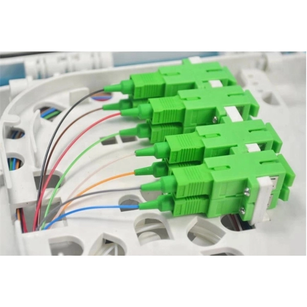
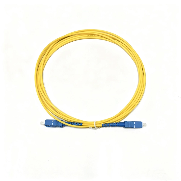
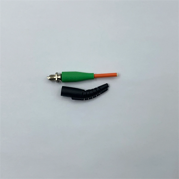
A PLC splitter is a passive optical device that divides one incoming optical signal from an input fiber into multiple output signals across several output fibers. PLC splitters utilize a planar lightwave circuit chip made of silica glass waveguides to distribute the optical power. PLC optical splitters (planar waveguide optical splitter) is a key component in optical fiber communication networks and is widely used in optical fiber distribution systems such as FTTH (fiber to the home) and PON (passive optical network). This passive yet sophisticated device utilizes integrated optics technology to split a single input signal into multiple. PLC splitter, also called Planar Waveguide Circuit splitter, is a device used to divide one or two light beams into multiple light beams uniformly or combine multiple light beams to one or two light beams. This helps share signals in fiber optic networks. Pick the split ratio that matches what you need. Lower ratios work for fewer users. Choose the connector type like SC, LC, or FC.
[PDF]
These beamsplitters are made by coating the hypotenuse of dual prisms with a partially reflecting material and joining them together using optical or epoxy cement. They eradicate the ghosting phenomenon because the transmitted beam is consistent with the incident light beam. A beam splitter or beamsplitter is an optical device that splits a beam of light into a transmitted and a reflected beam. It is a crucial part of many optical experimental and measurement systems, such as interferometers, also finding widespread application in fibre optic telecommunications. This division allows for the simultaneous analysis or utilization of the light's properties along two separate paths. These tools can split both laser and regular light. Image Credit: Shanghai Optics Most plate beamsplitters are. 📦 For purchasing, use the RP Photonics Buyer's Guide for beam splitters. It provides an expert-curated supplier directory, buyer-focused technical background information, and structured selection criteria to support professional procurement decisions. Beamsplitters are often classified according to their construction: cube or plate. Beam splitters are used to manipulate and control light, making them valuable devices in both classical and quantum optics. A beam splitter is capable of introducing phase shifts and quantum superpositions, making them a core component of quantum technologies such as quantum computing and Quantum.
[PDF]
At its core, a fiber optic splitter relies on the principles of light reflection, refraction, and waveguiding to divide signals. Its design varies by type, but the underlying mechanism involves manipulating light to distribute its power across multiple output ports. A fiber optic splitter is a passive optical component that divides a single incoming optical signal into two or more outgoing signals, or combines multiple incoming signals into one. Their ability to efficiently manage optical signals makes them indispensable in various. This guide will demystify this pivotal passive device, exploring its types, working principles, and how it seamlessly integrates with optical transceivers to bring high-speed internet to your doorstep. 📄 What is an Optical Splitter? An Optical Splitter, also known as a beam splitter, is a passive. Fiber optic splitter is a passive optical device that includes multiple input and output ends. This principle allows a single input light beam to be split into N output light beams. The splitting can be achieved through two main methods: parallel beam splitting and beam divergence splitting. For example, an optical splitter.
[PDF]
Planar waveguide optical splitter (PLC Splitter) is a kind of integrated waveguide optical power distribution device based on quartz substrate, which has the characteristics of small size, wide working wavel.
[PDF]
In this paper, a thermally tuned silicon-based three-channel reconfigurable multimode interference (MMI) optical power splitter with four optimized thermal isolations is proposed. Specific and flexible reconfig-urable functions (1, , and MMI splitters) can be achieved by. Abstract: We demonstrate integrated photonic circuits for quantum devices using sputtered polycrystalline aluminum nitride (AlN) on insulator. 56(1), 017106 (2017), doi: 10. The two most common types of splitters offered are polarizing beam splitters and polarization maintaining beam splitters. Their operating principles are as follows: Polarization Maintaining. optical transimission & integration needs of any system. MEISU specializes in precise custom fiber array sub-assemblies and PM fiber optical components and assemblies for different areas like integrated optics, sensoring, healthcare, spectroscopy, etc., 50/50 FBS, can be used as the frequency-mode Hadamard gate for frequency-encoded photonic qubits. Quantum cryptography is the key point of quantum communication. In classical cryptography classical bits are used but in quantum cryptography quantum bits (qubit) are used. Quantum communication sends the information through some channels such that, optical fibre, satellite etc.
[PDF]
The working principle of fiber optic splitters is based on the 1:N splitting principle. The splitting can be achieved through two main methods: parallel beam splitting and beam divergence splitting. Optical splitter, also called optical beam splitter, is an integrated waveguide optical power distribution device that can split an input optical signal into two or more output optical signals, and the optical input power is evenly. A fiber optic splitter is a passive optical component that divides a single incoming optical signal into two or more outgoing signals, or combines multiple incoming signals into one. Unlike active devices (which require power), splitters operate without electricity, relying solely on the physics of. Additionally, the guide will cover the manufacturing processes, quality standards, and market trends specific to China. Optical splitter. This guide will demystify this pivotal passive device, exploring its types, working principles, and how it seamlessly integrates with optical transceivers to bring high-speed internet to your doorstep. 📄 What is an Optical Splitter? An Optical Splitter, also known as a beam splitter, is a passive.
[PDF]
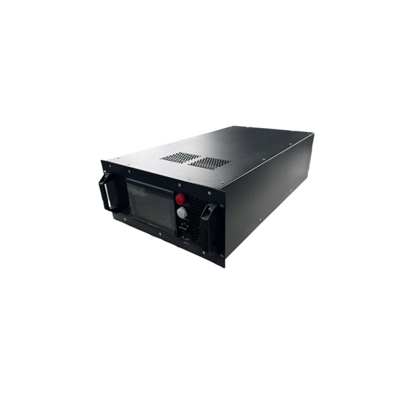
Their main function is to convert optical signals, which are transmitted through fiber optic cables, back into electrical Radio Frequency (RF) signals. This conversion is essential for delivering digital TV content to homes and other viewing locations. It's the endpoint of any fiber optic link, sitting at the far end of the cable and translating pulses of infrared light into the ones. Optical receivers are a crucial component in optical communication systems, playing a vital role in converting optical signals into electrical signals. In this comprehensive guide, we will explore the world of optical receivers, their significance in optical communications, and the key. An optical receiver functions as the final component in a fiber-optic link. The primary function of an optical receiver in digital TV setups is to facilitate the transmission of high-quality audio signals between. The term direct detection refers to the receiver configuration, where the received signal is applied directly to a photodetector (PD). The optical receiver is a combination of the optical detector, electronic preamplifier, and the electronic processing elements that recover information sent on the.
[PDF]
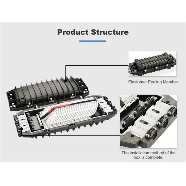
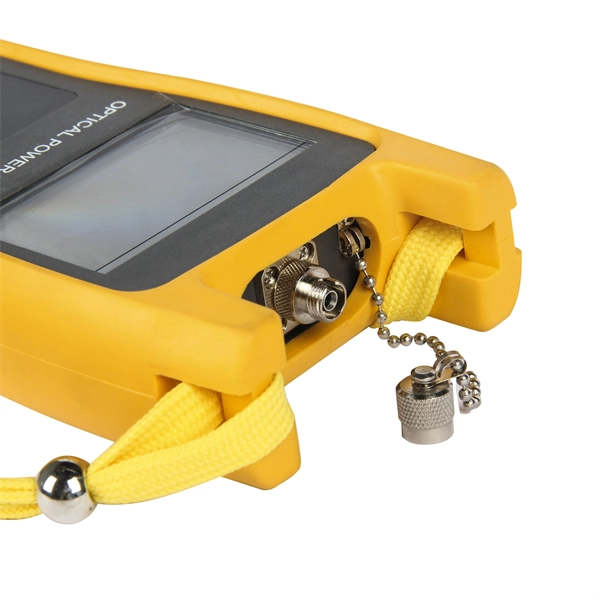
This video provides a step-by-step guide on how to efficiently install optical splitter into a fiber terminal box, demonstrating a professional and reliable deployment for optical distribution network solution ( https://www. com/c/optical-distribu. The following is a guide to installing and using a fiber optic splitter, including key steps and precautions: Required tools: Fiber cleaver, wire stripper, alcohol wipes/cleaning pen, optical power meter. Splitter Type: Choose a PLC type (uniform splitting) or an FBT type (non-uniform splitting). This adapter effectively provides Ethernet data and DC power to a non-PoE device with a single cable and allows it to operate within a PoE network. PoE is an efficient and convenient solution for remote applications where available space is limited and/or no power source is readily available. This manual provides safety and installation instructions for the 9490-OS Fiber Optic Passive Splitters. All units use type LC connectors and vary only in the splitting fan-out, and as single or dual-channel capability as listed below. All units are entirely passive and require no frame power or. After installing the mounting box or bracket, feed the 4-pair UTP (Unshielded Twisted Pair) cable through the wall opening. Strip off approximately 2" of the cable jacket, using the appropriate cable stripping tool. Separate the pairs according to color (Blue/Blue-White,Orange/Orange-White.
[PDF]
A PLC Splitter takes one optical signal and splits it into many outputs. This helps share signals in fiber optic networks. Pick the split ratio that matches what you need. Lower ratios work for fewer users. Choose the connector type like SC, LC, or FC. This. The optical splitter is an important passive device in the optical fiber link. It generally has one or two input ends and many outputs end for laser signal distribution. This article will explain the. Planar Lightwave Circuit (PLC) splitters play a vital role in modern fiber optic communication networks by enabling the efficient distribution of high-speed optical signals. It is one of the core components in Passive Optical Networks (PON) and is widely used in FTTx deployments, where a single fiber connection. This video provides a step-by-step guide on how to efficiently install optical splitter into a fiber terminal box, demonstrating a professional and reliable deployment for optical distribution network solution ( https://www. com/c/optical-distribu. more This video provides a step-by-step.
[PDF]
Frequent status changes from up to down or vice versa in the ports logged by the switch port syslog indicates a port flap. On a big industrial plant we've replaced an old HP switch with a brand new couple of C2960x switches in stack configuration and ever since then, every 6/8 hours or so, the two fiber optics links of switch #2 go down at once. These are connected to a ring of 3 similar other access switches, that. EX4650 2-switch virtual chassis, running version 19. 2, optic p/n 740-031981 (SFP+-10G-LR) is plugged into port xe-0/0/10 and connected to an ISP via single mode fiber. Nothing special is configured on the port, it is running at 10G speed, show interfaces diagnostics optics shows that it's. This article describes steps to diagnose the Continuous port flapping on a FortiSwitch. Verify Cable Connection: Ensure the cable is properly connected between the switch port and the end device. Run the command below on FortiSwitch multiple times and check the. Real head scratcher this morning that I'm hoping someone can help me with! The port on our core switch (HP A5500) that our Smoothwall box is connected to keeps going up and down. Port flapping, also known as link flapping, causes a switch port's state to fluctuate between up and down within concise periods of time. This instability caused by flapping ports affects network connectivity. Port flapping is a common network issue that can disrupt communication between devices and degrade overall network performance.
[PDF]
Optical trap or "tweezers" is a device used to apply piconewton sized forces and make precise measurements on a scale of roughly one micron. It can be created by applying a precisely focused laser onto a dielectric material. Thorlabs' OTKB (/M) Modular Optical Tweezers provide users with a tool for trapping and manipulating microscopic-sized objects. These laser-based tweezers, or traps, have been employed in numerous biological experiments. Biological applications for optical tweezers include trapping viruses and. Our advanced optical trap generator based on ultra-fast AOD technology. Versatile and flexible optical trap manipulation designed for biological samples. Learn to calibrate the 20. Use calibration information to observe the rotation of E. coli bacteria, and determine the forces required to stop this rotation. Based on their design, Thorlabs has collaborated with the aforementioned authors to design an OTKB optical trapping kit that includes all necessary components and provides the same capabilities. Enclosed into a high-quality aluminum box and assembled onto the. Torr Scientific offers a range of magneto-optical traps (MOT) (also known as atom trap chambers) used as part of ultra-cold vacuum systems, to capture atoms for testing purposes. This is a chamber module, formed of low-magnetic permeability materials for use at ultra-low temperatures nearing.
[PDF]
In this Cisco Tech Talk, learn how to view the optical module status on a Cisco switch using the Command Line Interface (CLI). This video demonstrates how to access the optical module status, check for any issues, and monitor the health of your network's optical components. Learn. When optical modules operate on a switch, it is usually necessary to read the module's internal information to understand its working status—such as connection status and real-time metrics like optical power and temperature. Additionally, identifying module information helps detect coding. This chapter describes how to configure the Optical Amplifier Module and Protection Switching Module (PSM). When you plan to replace a configured optical module with a different type of optical module, you must clear the configurations of the old module before you install the new module. By checking module health, compatibility, and digital diagnostics, you can quickly confirm correct installation, detect optical problems, and maintain accurate hardware. Small Form-factor Pluggable modules (SFP module) are the workhorses of modern network connectivity, enabling flexible fiber optic or copper links between switches, routers, firewalls, and servers. Whether you're upgrading bandwidth, replacing a faulty unit, or reconfiguring your topology, knowing.
[PDF]
This Technical Brochure describes the induction phenomena (inductive, capacitive and conductive) that can lead to presence of voltage and currents on disconnected cable systems. The optical fiber composite overhead ground wire (OPGW) has been widely used in power transmission lines. Methods of calculation to evaluate those values and touch voltages are detailed and analysed, associated with various. working on cables u al, photocopying, recording or otherwise, without the prior written or use by members of the Energy Networks Association to take account of the conditions which apply to them. Advice should. Literature review: An in-depth literature review covering the modelling and calculations of the conditions relating to faults caused by interactions between fibre optic cables and power cores in submarine cables. Examples of electrically conductive installations where induced voltage may occur could be: • Overhead lines or cables out of opera- tion •.
[PDF]
The system in this example contains the following elements: 1. 2 Pseudo-random Bit Stream (PRBS) block 2. 2 NRZ Pulse Generator (NRZ) 3. 1 CW Laser (CWL) 4. 3 1x2 Fork (FORK) 5. 2 Electrical Not Gate (N.
[PDF]
ExxonMobil Guyana's fibre optic cable has landed, Guyana Vice President Bharrat Jagdeo said during a December 28 press conference. Ongoing construction of an offshore command centre at Ogle, East Coast Demerara, is expected to conclude this year. Prime Minister Bridgadier (Ret'd) Mark Phillips commissioned a new multi-billion-dollar direct submarine fibre-optic cable, marking a historic moment for the region and closing the long-standing digital gap between the coastland and the hinterland. The milestone ushers in gigabit-speed. ENet has completed a transformative multibillion dollar telecommunications project, landing the first ever direct submarine fiber‑optic cable to Bartica. This pioneering investment brings state-of-the-art fiber connectivity and 5G mobile service to the hinterland town, connecting Bartica directly. – PM Phillips says no region will be left behind in Guyana's digital transformation IN a ground-breaking development for Guyana's hinterland connectivity, Prime Minister Brigadier (Ret'd) Mark Phillips on Wednesday hailed the commissioning of the first-ever direct submarine fibre-optic cable to. Prime Minister Brigadier (Ret'd) the Honourable Mark Phillips hailed the commissioning of the first direct submarine fibre-optic cable to Bartica as a transformative development that brings the hinterland town in line with the capital city's digital capabilities. Speaking at the commissioning.
[PDF]