This report provides a comprehensive analysis of the optical active device market, encompassing various segmentations: By Type: Lasers, modulators, photodetectors, amplifiers, etc., each with their own specific performance characteristics and applications. The global Active Optical Devices market was valued at US$ million in 2023 and is anticipated to reach US$ million by 2030, witnessing a CAGR of % during the forecast period 2024-2030. The Global Info Research report includes an overview of the. Optical Active Device by Application (IT Industry, Telecom, Other), by Types (Optical Transceiver Module, Light Detector, Light Modulator, Other), by North America (United States, Canada, Mexico), by South America (Brazil, Argentina, Rest of South America), by Europe (United Kingdom, Germany. The Optical Active Device Market Size was valued at 36. 3 USD Billion in 2024. The Optical Active Device Market is expected to grow from 38. North American market for Active Optical Devices is estimated to increase from $ million in 2024. Abstract—A wireline receiver consisting of a linear equalizer, a decision-feedback equalizer (DFE), a clock and data recov-ery (CDR) circuit, and a demultiplexer (DMUX) employs new circuit and architecture techniques that afford substantial power savings. Realized in 28-nm technology, the 56-Gb/s.
[PDF]
Learn how to extend GDB with optical signal breakpoints for efficient photonics chip debugging and testing with practical implementation steps. Debugging photonics chips requires specialized tools that can monitor and analyze optical signals alongside electronic ones. Legal status (The legal status is an assumption and is not a legal conclusion. Google has not performed a legal analysis and makes no representation as to the accuracy of the status listed. ) Current Assignee (The listed assignees may be inaccurate. These modules leverage advanced signal processing, modulation, and high-speed interfaces to provide high bandwidth, low latency, and reliable performance. Standard debugging tools like. modules used with NADDOD switches, for reference by technicians and users. For any questions, please contact NADDOD. When testing PRBS, there are 3 test nodes: MAC ----> PHY. In view of this, the embodiments of the present invention expect to provide an optical module commissioning device, commissioning method, and electronic equipment to solve the time-consuming technical problem of manually commissioning a DSFP optical module through a commissioning device in. Optical detection chips serve as essential components in intelligent optical computing systems, demonstrating crucial significance. These chips exhibit high sensitivity and broad wavelength response ranges, enabling precise optical signal reception and conversion while providing reliable data input.
[PDF]
Choosing between single-mode and multi-mode optical fiber shapes the performance ceiling of every high-bandwidth industrial sensing network. This guide maps the key technical distinctions, applicable standards, and the most productive research directions for. Optical fibers are among the most transformative technologies in modern photonics, quietly enabling the global internet, precision sensing, minimally invasive medicine, and high-power industrial laser systems. The. Discover ROI-boosting fiber choices: Single Mode vs Multimode Fiber. Get the right speed & savings for your network—download our guide for free today! Understanding the physics behind Single Mode vs Multi‑Mode Fiber is essential for selecting the right conduit for any optical network. Single‑mode. Choosing single mode or multi-mode installation is unquestionably one of the most crucial decisions. Understanding the distinctions between these two kinds of fiber glass are crucial since it will have a significant impact on your network's range, bandwidth, and spending. Single mode means the. Optical fiber cable transmits data as light at speeds exceeding 100 Gbps, far surpassing the 10 Gbps capabilities of legacy Cat 6A copper cable. Additionally, optical fibers support significantly higher bandwidths over greater distances without signal degradation. While both use light to transmit data, they differ fundamentally in core structure and how light travels.
[PDF]
Polarization dependent loss (PDL) is a measure of the peak-to-peak difference in transmission of an optical component or system across all possible states of polarization. It is the ratio of the maximum and minimum transmission of an optical device with respect to all polarization. The determination of polarization dependent loss has become a stan-dard measurement when character-izing passive optical components. In optical networks, where polarization is not constrained and changes randomly, the PDL of components can accumulate in an uncontrolled manner. This effect can. arch, and 3) Matrix measurements using Mueller or Jones matrices. Each method has its own advantages and disadvantages in terms of measuremen ice under test (DUT) while the DUT's output power is monitored. The built-in motor con-trolled PDLE units have low insertion loss, low backreflection, low PMD and flat wavelength response. This. This is the authors' extended version of an article that has been published in Proc. 21th ITG-Symposium on Photonic Networks, ISBN 978-3-8007-5424-3. The final version of record is available at https://www. de/buecher/455423/itg-fb-294-photonische-netze. Abstract—A number. Abstract—State-of-the-art polarimeter calibration is reviewed. Producing many quasi-random polarization states and moving/bending a fiber without changing power allows finding a polarimeter calibration where the degree-of-polarization reaches unity and parasitic polarization-dependent loss is.
[PDF]
Co-Packaged Optics (CPO) is an emerging technology that integrates optical engines directly with electronic switching chips to enable higher bandwidth, lower power consumption, and improved signal integrity in next-generation data centers and high-performance computing systems. As applications like AI and machine learning become more prevalent, demanding higher bandwidth data processing capabilities, CPO technology provides a scalable solution that can grow with these needs. Corning is taking part in the co-packaged optics revolution with our innovative fiber and optical. Co-packaged optics (CPO) is a disruptive approach to increasing the interconnecting bandwidth density and energy eficiency by dramatically shortening the electrical link length through advanced packaging and co-optimization of electronics and photonics. CPO is widely regarded as a promising. The relentless surge of artificial intelligence, hyperscale computing, and next-generation networks is exposing the limitations of traditional pluggable optical transceivers. Electrical signal integrity challenges, escalating power consumption, and physical density constraints at speeds exceeding. Traditional optical interconnects have long been used in networking applications, but silicon photonics takes the technology a step further by integrating optics directly into semiconductor chips (FIGURE 1). But after nearly a decade of existence, where does this next-generation optical.
[PDF]
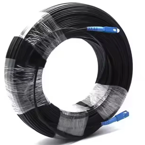
Fiber optic "cable" refers to the complete assembly of fibers, other internal parts like buffer tubes, ripcords, stiffeners, strength members all included inside an outer protective covering called the jacket. Cable provides protection for the optical fiber or fibers within it appropriate for the environment in which it is installed. You will also learn how different aspects of the product can affect budget and design. ■ The Five Key Parts of a Fiber Optic Cable A fiber optic cable. A fiber optic cable consists of five basic components: the core, the cladding, the coating, the strengthening fibers, and the cable jacket. When searching for a fiber optic cable, we need to pay attention not only to the connectors, such as SC to ST fiber cable, LC to SC fiber patch cable, or SC to. A TOSLINK optical fiber cable with a clear jacket. These cables are used mainly for digital audio connections between devices. This advanced cabling solution allows fast, secure data transfer and telecom over long distances. Understanding the components within a fiber optic cable enables. While fiber optic cable itself is cheaper than an equivalent length of copper cable, fiber optic cable connectors and the equipment needed to install them have typically been more expensive than their copper counterparts.
[PDF]
Several common cable outer sheath materials are PVC, PE, LSZH, AT and rodent-proof sheath materials. PVC is the most widely used fiber optic cable outer sheath material. What Is a Cable Sheath and Why It Matters 🔍 The cable sheath is the outer protective layer of a fiber optic cable. Its primary functions include: While the optical fiber itself remains largely unchanged, the sheath material determines how the cable behaves in fire scenarios, outdoor environments. The main function of the fiber cable outer sheath is to protect the optical fibers in the optical cable from external damage. At the same time, it must have. PVC vs LSZH vs TPU: Which sheath material for fiber optic cables in 2026? The jacket material determines the reliability, fire resistance, and lifespan of a fiber optic cable. At the same time, it must have. If so, then do remember that Fiber cables are made with high-grade glass cores and environmental protective sheaths, which can endure everything from residential network connections to underwater links. In this article, we'll discuss in detail the construction of Fiber optic cables and also see the. The sheath or outer sheath is the outermost protective layer in the optical cable structure, mainly made of PE sheath material and PVC sheath material, and halogen-free flame-retardant sheath material and electric tracking resistant sheath material are used in special occasions.
[PDF]
The CFP standard defines a pluggable optical transceiver form factor capable of supporting 40G and 100G Ethernet, OTN (Optical Transport Network), and SONET/SDH protocols. The acronym "CFP" represents the Roman numeral "C" (100), aligning it with 100 Gigabit Ethernet. Originally introduced as the first standardized pluggable solution for 100 Gigabit Ethernet, CFP (C Form-factor Pluggable) modules were engineered to support high-bandwidth, long-distance transmission using multiple optical lanes. Their robust design made them ideal for carrier-grade networks, DWDM. The C form-factor pluggable (CFP, 100G form factor pluggable, where C is Latin: centum "hundred") is a multi-source agreement to produce a common form-factor for the transmission of high-speed digital signals. Developed collaboratively. The CFP optical transceiver module is a standardized, hot-swappable optical transceiver used for high-speed data transmission in telecommunications and data center networks. CFP transceivers are defined by CFP MSA to enable 40 Gb/s, 100 Gb/s and 400 Gb/s applications. It features a new concept known as. This article breaks down the key differences between CFP, CFP2, CFP4, and CFP8 optical transceivers commonly used in fiber optic networks. Figure 1: Dimensions of CFP, CFP2, CFP4, and CFP8 The table below summarizes the specifications of each form factor: 24 W (Max. ) In essence, the progression.
[PDF]
BARCELONA, Spain, March 6, 2025 /PRNewswire/ -- At the Mobile World Congress 2025 (MWC 2025), Huawei launched the StarryLink optical modules, designed to enhance network experiences with "3S" quality (Spanning, Stable, Secure). This announcement occurred during the data center session titled. Very little is written about Huawei's optical DWDM technology, but that doesn't mean the company hasn't made some big waves in the industry. We had the chance to sit down with the Huawei optical team, led by Gavin Gu, at MWC 2026 to learn about their latest coherent DWDM technology.
[PDF]
The system in this example contains the following elements: 1. 2 Pseudo-random Bit Stream (PRBS) block 2. 2 NRZ Pulse Generator (NRZ) 3. 1 CW Laser (CWL) 4. 3 1x2 Fork (FORK) 5. 2 Electrical Not Gate (N.
[PDF]
Calibration & Repair services in Ireland. 5 day turn around with competitive pricing! View full electrical test and measurement equipment list here. is an independent calibration laboratory focused on meeting the total quality requirements of industry. Proper calibration of today's sophisticated test and measurement equipment is essential for preserving measurement accuracy, complying with international standards. Parameters covered include; Temperature, Humidity, Dewpoint, Various Gases, Pressure, Electrical, Weights & Scales, Analytical and some Specialist calibrations. Calibration is performed using the very latest Calibration Equipment/Standards & Calibration/Asset Management Software. Fast Efficient. PTM Calibration offers a wide range of services that complement our core business. We aim to be your one stop shop for all your calibration, test & measurement needs. From major blue chip companies & medium enterprises to small companies and sole traders. Including: aerospace, pharmaceuticals. OptiCal Sciences are an authorised service centre with service, repair and calibration experience and procedures for an extensive variety of models from a wide range of manufacturers.
[PDF]
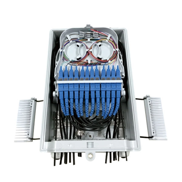
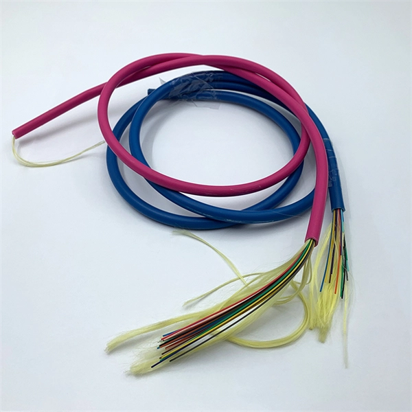
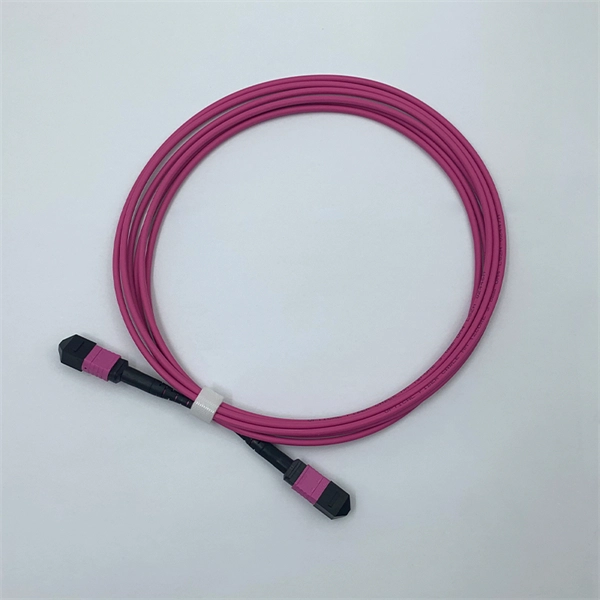
Total number of cores = Number of branches × Number of cores per branch If there are no branches, the number of branches equals one. For example, an MTP®-8 trunk cable with four branches and eight cores per branch has a total of 32 cores (4 × 8 = 32). For example, if you have three optical fiber access switches, you need to have three cores. (actually use a four core optical cable) This is because apart from one-core optical fiber, there are basically no optical cables with an odd number of cores, such as three-core, five-core, etc. It is worth. Fiber cores are the heart of fiber optic cables, transmitting light signals that carry data. Made from either high-quality glass or plastic, the core plays a critical role in determining the cable's performance. The total number of cores for a 1pc fiber patch cable is calculated as the number of. One key factor is the number of cores, which impacts how much data you can transmit. Single-mode: A. Common fiber cores include 1 core, 2 cores, 6 cores, 8 cores, etc., and there are many types. This article will focus on the number of fiber cores, introducing their respective characteristics and usage scenarios. Of course, this is a general situation, and it can be considered as follows: 1.
[PDF]
The SFP optical module is a standardized, modular assembly designed to be quickly installed or removed from a device's port without requiring the device to be powered down. This key feature—being hot-pluggable —is essential for simplifying network maintenance and minimizing downtime. SFP (Small Form-factor Pluggable) is a compact, hot-pluggable network interface module used to connect network devices (switches, routers, firewalls) to fiber optic or copper cables. It converts electrical signals into optical (or copper) signals and vice versa. An SFP transceiver acts as a compact, hot-swappable optical transceiver that. An SFP switch uses Small Form-Factor Pluggable (SFP) modules to form a network switch for high-speed connectivity between devices. These interchangeable modules support various media types, including copper or fiber-optic cables, providing flexible networking options based on specific requirements.
[PDF]
XGS-PON is a 10 Gbps symmetric passive optical network (X=10, S=symmetric). Optical fiber's greater transmission capacity and speed deliver upstream and downstream (symmetric) speeds of up to 10 Gbit/s (gigabits per second) on the road to connecting users in the last. 10G-PON (also known as XG-PON or G. 987) is a 2010 computer networking standard for data links, capable of delivering shared Internet access rates up to 10 Gbit/s (gigabits per second) over optical fibre. This is the ITU-T 's next-generation standard following on from GPON or gigabit-capable PON. It is commonly used to implement the link to the customer (the last kilometre, or last mile) of fibre-to-the-premises (FTTP) services, using a. Short on Ethernet ports and looking to connect an extra device or two to your wired network setup? You're likely to encounter two options: an Ethernet splitter, and an Ethernet switch. Here's why you should choose the switch every time. What Is an Ethernet Splitter? An Ethernet splitter is a simple. Recommendation ITU-T G. 1 describes a flexible optical fibre access network capable of supporting the bandwidth requirements of business and residential services and covers systems with nominal line rates of 2. 4 Gbit/s in the downstream direction and 1. 984 G-PON and ITU-T G. 9807 XGS-PON wavelengths to coexist within the same single mode fiber cabling and across the same passive optical distribution splitters. This means that users can.
[PDF]
Optical trap or "tweezers" is a device used to apply piconewton sized forces and make precise measurements on a scale of roughly one micron. It can be created by applying a precisely focused laser onto a dielectric material. Thorlabs' OTKB (/M) Modular Optical Tweezers provide users with a tool for trapping and manipulating microscopic-sized objects. These laser-based tweezers, or traps, have been employed in numerous biological experiments. Biological applications for optical tweezers include trapping viruses and. Our advanced optical trap generator based on ultra-fast AOD technology. Versatile and flexible optical trap manipulation designed for biological samples. Learn to calibrate the 20. Use calibration information to observe the rotation of E. coli bacteria, and determine the forces required to stop this rotation. Based on their design, Thorlabs has collaborated with the aforementioned authors to design an OTKB optical trapping kit that includes all necessary components and provides the same capabilities. Enclosed into a high-quality aluminum box and assembled onto the. Torr Scientific offers a range of magneto-optical traps (MOT) (also known as atom trap chambers) used as part of ultra-cold vacuum systems, to capture atoms for testing purposes. This is a chamber module, formed of low-magnetic permeability materials for use at ultra-low temperatures nearing.
[PDF]