Welcome to our light sources category, where we offer advanced calibration solutions designed for precision and accuracy in scientific measurements. Our selection encompasses two primary subcategories: “Wavelength Calibration” and “Radiometric Calibration,” featuring state-of-the-art products. This. As a result of a 2-year research project, finalised in 2020, GL Optic developed new calibration facilities and created Calibration and Research Laboratory of Optical Radiation ( CARLO ). Today, CARLO is the only laboratory in Central and Eastern Europe equipped with the Black Body Radiator – the. We offer two types of light sources for calibration: Pen-Ray line sources for the wavelength calibration of spectroscopic instruments and calibrated irradiance sources covering UV-NIR. All Avantes spectrometers are factory wavelength calibrated and do not require recalibration as they have fixed slits and optics. Options include mercury-argon (253-1700 nm), krypton (427-893 nm), neon (540-754 nm), argon (696-1704 nm) and xenon (916-1984 nm) gas-discharge emission sources. Multiple LED sources can be efficiently combined into a single output beam, and offer major advantages such as long life-time, easily tunable spectrum, high power stability, and ultra-fast switching (on the microseconds level) without using moving mechanical components. Multi-Wavelength Collimated.
[PDF]
Typically made of glass, a beam splitter divides the light passing through it at a ratio. Usually, half of the light is reflected at an angle, and the other half is transmitted to the opposite side of the light source. A beam splitter or beamsplitter is an optical device that splits a beam of light into a transmitted and a reflected beam. It is a crucial part of many optical experimental and measurement systems, such as interferometers, also finding widespread application in fibre optic telecommunications. This division allows for the simultaneous analysis or utilization of the light's properties along two separate paths. a laser beam) into two (or sometimes more) beams, which may or may not have the same optical power (radiant flux).
[PDF]
It enables uniform, shadow-free lighting by directing light along the same optical axis as the lens. When integrated into specialised lenses, the beam splitter divides the incoming light into two paths: one beam illuminates the object, while the other is used for image capture. Beamsplitters are fundamental components in optical engineering, serving to precisely divide a single input beam of light into two distinct output beams. This division allows for the simultaneous analysis or utilization of the light's properties along two separate paths. Additionally, beamsplitters can be used in reverse to combine two different beams into a single one. In practice, the reflective layer absorbs some light. It is a crucial part of many optical experimental and measurement systems. A cube beam splitter is, at its essence, an optical device that splits an incoming light beam into two sections. What are beamsplitters and how are they used in optics and photonics applications ? Beamsplitters are optical components that are used to. The beam splitter splits and then recombines infrared radiation, while the detector picks up the resulting signal. It's sensitive to both intensity and frequency. Together, they decide just how accurately an instrument captures those unique infrared “fingerprints” from different substances.
[PDF]
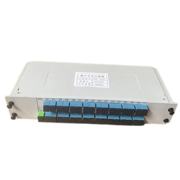
In fiber-optic communications, wavelength-division multiplexing (WDM) is a technology which multiplexes a number of optical carrier signals onto a single optical fiber by using different wavelengths (i.e., colors) of laser light. This technique enables bidirectional communications over a single strand of fiber (also called wavelength-division duplexing) as well as multiplication of capacity. The. SystemsA WDM system uses a at the to join the several signals together and a at the to split them apart. With the right type of fiber, it is possible to have a device that does both s. Originally, the term coarse wavelength-division multiplexing (CWDM) was fairly generic and described a number of different channel configurations. In general, the choice of channel spacings and frequency in these co.
[PDF]
Light decay in light divisions refers to the decrease in light intensity as it travels through optical fibers or other transmission media. This decay can occur due to a number of factors, including absorption, scattering, and reflection. If you don't know what kind of losses to expect in your system, you won't know how many other components. It is also known as fiber loss or signal loss. The signal attenuation of fiber determines the maximum distance between transmitter and receiver. Another important property of optical fiber is. Fiber loss, also called fiber optic attenuation or attenuation loss, refers to the loss of signal between input and output. Losses can be introduced by various means such as intrinsic material absorption, scattering, bending, connector loss and more. This loss can significantly reduce the effectiveness of optical fibers in applications such as telecommunications, imaging systems, and even simple fiber-optic tools like flashlights. In the early days of.
[PDF]
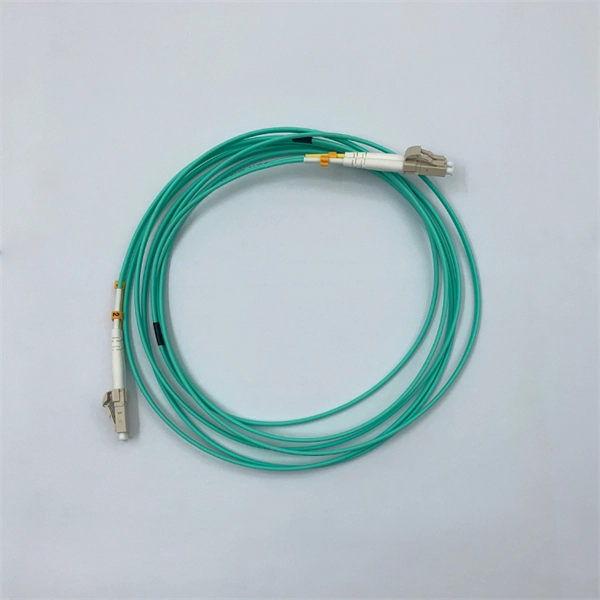
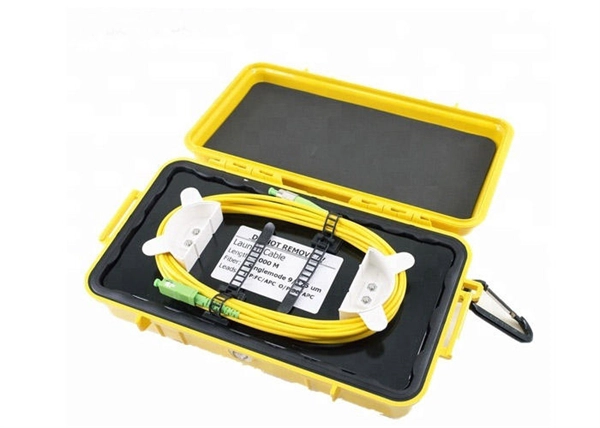
Singlemode fiber features a small core diameter of just 9 µm and allows only one mode of light to propagate. This design minimizes signal loss and supports high-bandwidth applications over long distances. 5 µm) with multiple light. Single-mode fibers (also called monomode fibers) are optical fibers which are designed such that they support only a single propagation mode (LP 01) per polarization direction for a given wavelength. Higher-order modes like LP 11, LP 20 etc. It allows just one light signal – typically lasers – to pass through at a time. This keeps the signal tight and strong, making it ideal for long. Optical Fiber comes in two main categories: singlemode and multimode. Singlemode fiber is designed for long-distance data transmission, typically over distances greater than 10 kilometers. Glass or plastic are often used to make these fibers. Metal wires are used in optical fibers because they protect against damage and are immune to electromagnetic interference. This characteristic allows for significantly less signal degradation and higher data rates over.
[PDF]
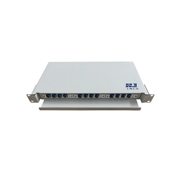
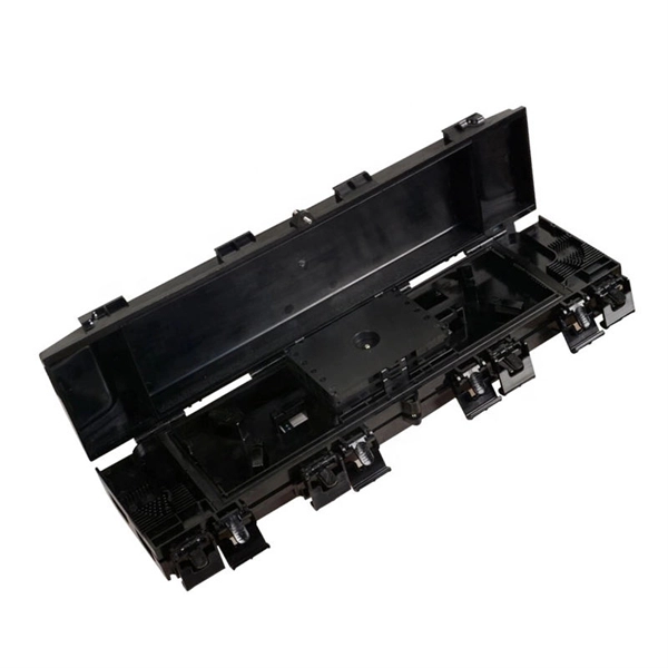
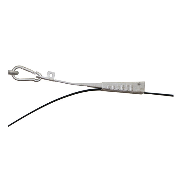
Through the adapter in the distribution box, the optical signal is led out by the optical jumper to realize the optical wiring function. An optical cable consists of three primary parts: the core, the cladding, and the protective sheath. The core is at the center of the optical cable and serves as the pathway for transmitting light signals. Surrounding the core is the cladding, which has a lower refractive index than the core. In the complex architecture of fiber optic networks, the Optical Distribution Frame (ODF) serves as the linchpin for organizing, protecting, and distributing optical signals. Whether in data centers, telecom central offices, or enterprise network rooms, ODFs enable efficient fiber management. The optical fiber distribution box is to protect the connection point where the optical cable is connected to the user end, so that the optical cable access point is stable, dustproof and waterproof. What is a fiber distribution box? 2. The. A fiber distribution box (FDB) functions as a central hub in fiber optic networks where the main cable is split into multiple individual fibers for distribution to end users. These boxes protect sensitive fiber connections from environmental factors while providing an organized framework for.
[PDF]
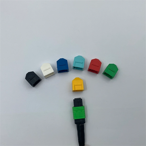
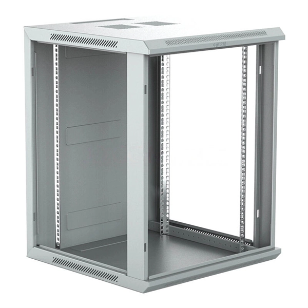
Our products cover MPO connectors, optical time-domain reflectometers (OTDR), optical cable joint boxes, optical fiber distribution boxes, optical cable cross-connect cabinets, etc. We provide comprehensive optical communication solutions and are a professional optical fiber. Haian Guangyi Communication Technology Co. specializes in manufacturing a full range of passive optical components, including optical splitters, optical fiber connectors, ODN products, and optical communication test instruments. These sequences are similar to bacterial DNA and are recognized by Toll-like receptor 9 (TLR9), an essential component of the innate immune. ODU series ODF sub-rack could be classified to integrated splicing & termination sub-rack and separated splicing & termination sub-rack. It usually is used in ODF rack or other telecommunication cabinets. ) specializes in providing the complete FTTH Product Series, ensuring that every decibel of optical power is preserved from the core to the customer. A standard FTTH ODN is divided into four critical segments. Weunion provides. CpG oligodeoxynucleotides (CpG ODNs) are synthetic DNA molecules characterized by short, single-stranded structures containing unmethylated CpG motifs derived from bacterial DNA. Pre-clinical studies and trials have demonstrated that CpG ODNs can significantly improve vaccine-specific antibody responses. CpG ODNs possess a partial or complete phosphorothioate.
[PDF]
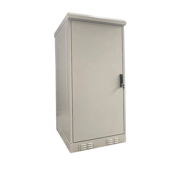
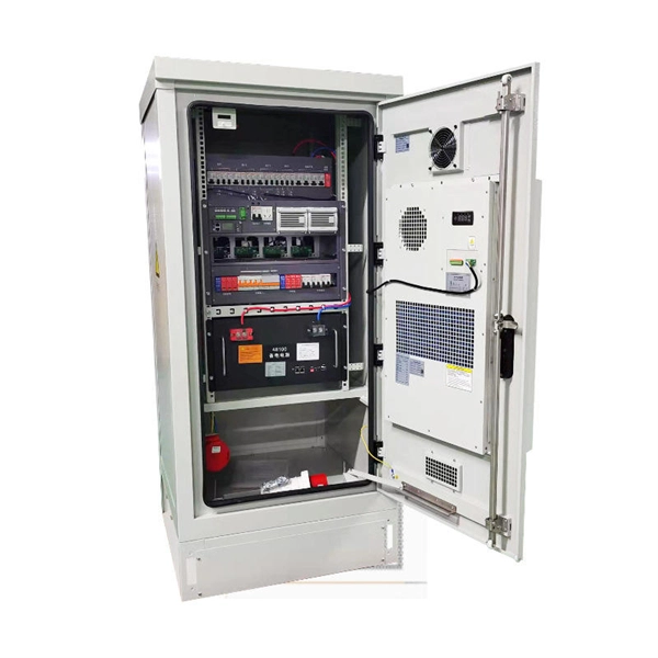
The XL-21 type low-voltage power distribution cabinet is an indoor fixed enclosed complete set of equipment that complies with IEC 60439-1 and GB 7251. It is specially designed for 50Hz AC power distribution systems with a rated voltage of 380V/660V and a rated current of. Standard Type (P Type): This version has a cabinet height of 1700mm or 1800mm and is designed for independent installation. It can be equipped with entry and exit holes at the top as required. Busbar Type (M Type): This version features a cabinet height of 1900mm or more, with a removable cover on. The Fulleto XL-21 series is an indoor, floor-standing power distribution cabinet engineered for excellence. It serves as the central hub for receiving and distributing electrical energy in low-voltage systems up to 380V. Designed for power plants, substations, industrial enterprises, and commercial. The XL-21 Power Distribution Box is used for power distribution, conversion, transmission, control, and on-site operations in low-voltage distribution systems. It is widely applied in power plants, substations, petroleum, chemical, metallurgy, machinery, and high-rise buildings. The XL-21 Power. The XL-21 type power distribution cabinet is a crucial component in electrical systems, designed to distribute power efficiently and safely across various industrial and commercial applications.
[PDF]
Customers close to a distribution transformer are able to have service drops directly connected to transformer secondary connections. Other customers are reached by routing a secondary main for servic.
[PDF]
Long-pass dichroic beam splitters are designed to transmit longer wavelengths of light and reflect shorter wavelengths, while short-pass dichroic beam splitters do the opposite. While this type of beam splitter is less common, it can be useful for fluorescent applications, such as. A beam splitter or beamsplitter is an optical device that splits a beam of light into a transmitted and a reflected beam. It is a crucial part of many optical experimental and measurement systems, such as interferometers, also finding widespread application in fibre optic telecommunications. In its. Beamsplitters are optical components used to split incident light at a designated ratio into two separate beams. Additionally, beamsplitters can be used in reverse to combine two different beams into a single one. Newport offers a wide variety of Beamsplitters in various shapes. a laser beam) into two (or sometimes more) beams, which may or may not have the same optical power (radiant flux). These plates are typically made of high-quality glass coated with a thin, anti-reflective film. The coating helps to minimize issues with annoying back reflections, such.
[PDF]
The AOI impacts the amount of light being reflected and transmitted. For example, most plate beam splitters have an AOI of 45 degrees, which may limit those who need more flexibility. A beam splitter or beamsplitter is an optical device that splits a beam of light into a transmitted and a reflected beam. It is a crucial part of many optical experimental and measurement systems, such as interferometers, also finding widespread application in fibre optic telecommunications. a laser beam) into two (or sometimes more) beams, which may or may not have the same optical power (radiant flux). Their precision and versatility make them indispensable in a variety of scientific, industrial, and technological applications. Beamsplitters are often classified according to their construction: cube or plate. Beamsplitters are fundamental components in optical engineering, serving to precisely divide a single input beam of light into two distinct output beams. This division allows for the simultaneous analysis or utilization of the light's properties along two separate paths. The device is purely. The beam splitter splits and then recombines infrared radiation, while the detector picks up the resulting signal. It's sensitive to both intensity and frequency. Together, they decide just how accurately an instrument captures those unique infrared “fingerprints” from different substances.
[PDF]
Resolving these issues involves steps like checking cable connections, soft resets, updating firmware, and specific solutions for different router brands like ASUS and Spectrum. It often indicates that something is wrong with your internet connection or the device itself. Fortunately, diagnosing and resolving these issues doesn't have to be complicated. In this comprehensive guide, we will walk you through the common causes of a red light on your router and provide. A router showing a red light can mean different things, like a service outage, misconfiguration, or loose connection, all of which can lead to a broken internet connection. Fortunately, there are heaps of ways to fix a red blinking light on your router. One of the first things you should try is to. Turn off the router and disconnect the power cord. Check that the PON cable is free from damage or sprains. Even if you have the best router, you may experience a loss of connection or other issues and see that dreaded red light. When it's green and steady, everything is fine. However, when it blinks red or stays solid red, it signifies a Loss of Signal, a problem preventing your router from communicating.
[PDF]