Converting multimode fiber to single-mode fiber can improve network performance and future-proof infrastructure. This guide will walk you through the methods, challenges, and best practices for successfully converting multimode to . This guide will break down the professional methods to achieve seamless single-mode to multi-mode conversion, ensuring your network integrity and performance. 📝 Why Can't You Directly Connect SMF and MMF? At its heart, the incompatibility is physical. The core size of multi-mode fiber is. How can we convert the multimode to a singlemode fiber system? This complete guide will provide answers to these questions. Mode conversion is typically required when: FlexPoint unmanaged Fiber-to-Fiber Media Converters provide multimode to single-mode conversion, and support a variety of network. Fiber mode conversion, especially multimode to single-mode fiber conversion (MMF-to-SMF conversion) is required when the distance is an important parameter to consider in optical applications. In this tutorial, three methods will be introduced to support mode conversion from multimode to. Multimode fiber (MMF) and single-mode fiber (SMF) are two types of fiber optic cables utilized for transmitting light signals over extended distances (For details, please refer to the blog post “ Choosing the Right Fiber Optic Cable: Singlemode vs Multimode “). The primary distinction between them.
[PDF]
Dual fiber modules use two fibers. They are easier to set up and give steady communication. Single-mode optical modules are best for long distances and fast speeds. They use a thin fiber core. They cost less and are easier. Multi-mode optical fiber is a type of optical fiber mostly used for communication over short distances, such as within a building or on a campus. Multi-mode fiber has a fairly large core diameter that enables multiple light modes to be. Single fiber modules (BiDi) use one fiber for both transmitting and receiving data. This saves space and money. multimode refers to the type of fiber core and how light travels inside it. It is widely used in local area networks, data centers, and other applications where high-bandwidth connectivity is required. Single-mode fiber, as the name suggests, transmits a single light mode. It has a narrow core diameter of 8-10 microns and uses a laser or.
[PDF]
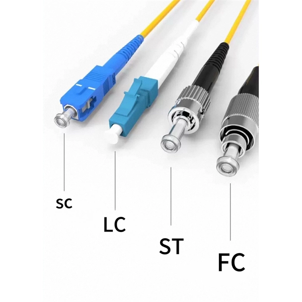
In 2007, a new type of "bend-insensitive" singlemode fiber was introduced, followed by multimode fiber in 2009. Bending losses are a function of the fiber type (SM or MM), fiber design (core diameter and NA), transmission wavelength (longer wavelengths are more sensitive to stress) and cable design. This guide explores the science behind bend-insensitive fiber, its key types (single-mode and multimode). Bend-Insensitive Fiber: Types, Benefits & Applications Get Your Best Price Now! Skip to content HOME Products FTTA Solution FTTA Patch Cord FTTA Enclosure Data Center Solution MPO/MTP Cassette MPO/MTP Patch Panel MPO/MTP/MMC Patch Cord MPO/MTP Adapter Passive Components Fiber Patch Cord Adapter. Bend-insensitive fiber (BIF) is fiber optic cable that doesn't lose transmission power even when bent beyond its average radius. The cable has an extra layer of material around its core that prevents light from escaping. In this case we can think about 1310nm and 1550nm which are the wavelengths used in singlemode fiber. There are two main types of fiber optic cables: single mode and multimode. Although they can do the same job in some instances, the different construction methods make each of them better suited to certain tasks and budgets. That makes picking between single mode and multimode fiber optic cables an.
[PDF]
The coupling of Laguerre-Gaussian (LG) vortex modes into the Bessel vortex modes in a multimode fiber was analyzed using the vector form of LG beams. A formula for estimating the transmission coefficients of the excited vortex modes was developed. Calculation of the coupling ratio of a gaussian beam directly injected into a multimode fiber optic. Focusing the light normal to the fiber face produced a near-Gaussian output beam profile (Figure 169A) and increasing the angle resulted in top hat (Figure 169B) and donut-shaped. Multimode beams are light beams in free space or in transparent optical materials which involve multiple spatial modes. The conceptually simplest situations are encountered in cases involving waveguide structures such as optical fibers, where there is a well-defined set of waveguide modes, and the. We investigate the input and propagation characteristics and geometric parametric instability of the partial Gaussian beam limited by the fiber face area in a graded-index multimode fiber. The theoretical simulation shows that the energy of the partial Gaussian beam and the coupling efficiency of. The power coupling efficiency of an elliptical-spot-size Gaussian beam into a multimode step-index fiber is derived using a full-wave analysis. Analytical calculation results show that the.
[PDF]
Single mode and multimode fiber optic cables are two different types of fiber optic cable aimed at different use cases. Single mode cables are typically made with a single strand of glass at their core, leading to a n.
[PDF]
This guide reveals the secrets to fusion splicing with little fluff—just proven, straightforward techniques refined from years of work in the field. In this guide, you will find a chronological description of the fusion splicing process, the principal technical standards, and answers to the real-life questions network engineers and procurement teams may have. The guide provides the complete workflow, covering safety precautions, tool selection, fiber preparation, fusion operation, quality control, and. Summary: Fiber color codes, defined by the TIA-598-C standard, help technicians quickly identify individual fibers, buffer tubes, and connectors in multi-strand cables. Using proper color coding makes installation easier, speeds up troubleshooting, reduces downtime, and supports future network. When a tech opens a fiber optic cable to prepare it for splicing, they will find a colorful bundle of buffer tubes as on this armored cable. The colors of the buffer tubes and likewise the fibers in the tubes provide the identification the tech needs to complete the splicing of the fibers as the. Fusion splicing is the bedrock of high-performance fiber optic networks, enabling seamless signal transmission through permanent, low-loss fiber joins. By adopting the TIA/EIA‑598C standard, you gain a universal “language” of colors that speeds identification, reduces miswiring, and enhances safety.
[PDF]
Merriam-Webster defines it as a “humorous internet slang term” meaning “to outclass,” typically used to describe someone as far more attractive than another. While forecasts are more uncertain in the spring and the strength of the upcoming warming phase remains very uncertain, NOAA is forecasting a 1-in-3 chance of a super El Niño by October, November and December. A super El Niño is defined as water temperatures being at least 2°C above average over. At its core, “mogging” is about comparison: when one person significantly outshines another in looks, physique, or even life status. Being “mogged,” on the other hand, means being on the losing end of that comparison. However, it does have some meaning depending on how it is used. Teens will often say 67 while making a hand gesture as if they're weighing things on a balance. Saying 67 with that hand gesture can mean “so-so” or “about”, but the emote can. While “SYBAU” sounds like the name of a luxury car or some new technology software, it's far from that. ICYMI, “SYBAU” is a Gen Z internet slang term that's popping up all over social media. Whether it's used in the caption of a TikTok, plastered in the comment section, or sent to you by your.
[PDF]
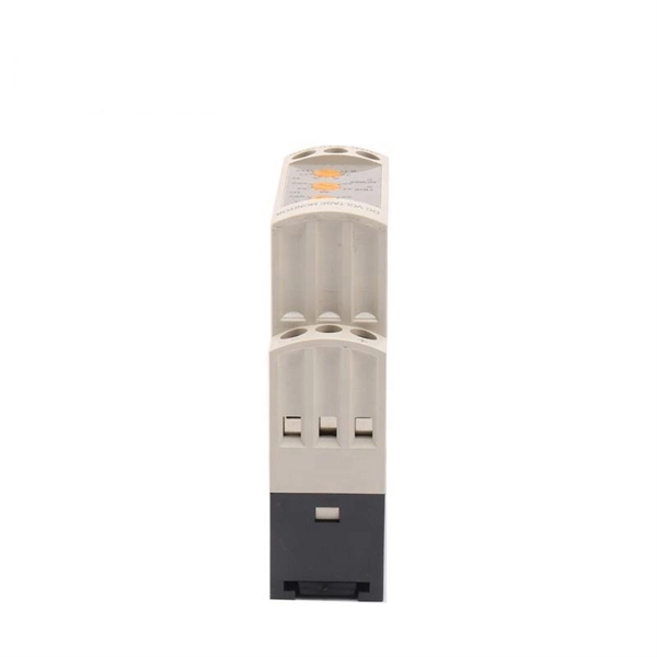
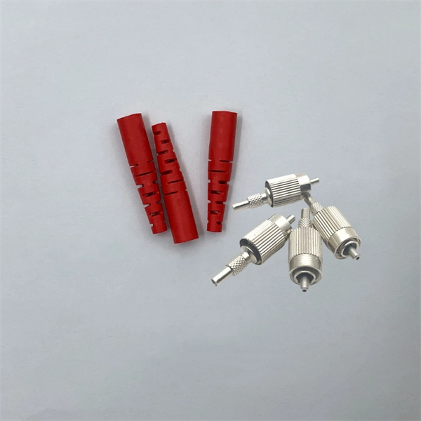
Generally, multimode systems do not need attenuators. Multimode sources, even VCSELs, rarely have enough power output to saturate receivers. Fiber optic attenuators, also called optical attenuators, are passive devices used to reduce the power level of an optical signal. Since too much light may saturate the fiber optic receiver, optical attenuators are often deployed in the system to reduce the light power and achieve the best fiber. Attenuators can be made by introducing an end gap between two fibers (gap loss), angular or lateral misalignment, poor fusion splicing (deliberately), inserting a neutral density filter or even stressing the fiber (usually by a serpentine holder or a mandrel wrap). It achieves this either by dispersing or absorbing the light without reflecting it. Also, by preventing overloading, attenuators can increase the lifespan of network.
[PDF]
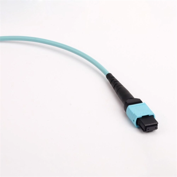
We are manufacturer of multimode patch cable in Argentina in China with expert certificate. As a very important a part of our business,a win-win. Identify and compare relevant B2B manufacturers, suppliers and retailers Max. FIBROMARKET ARGENTINA is a specialized manufacturer of products and solutions for optical fiber telecommunications networks, offering a range of tools including fusion splicers and OTDRs. If our selection of stocked patch cables does not meet your needs, we also offer custom patch cable services. Please use the form below to build and order your custom cable. If you find your. FCD offers TAA Compliant and Made in the USA fiber optic cables. We can custom build any length and type of fiber you need and we'll ship the order typically within 1-2 days. In addition, we are taking extreme caution to ensure that every shipment is properly sanitized for your peace of mind We. Get it 12 May, 2026 2518 in Global Warehouse. Get it 18 May, 2026 Get low-loss fiber patch cables & cords with various connector options that support fiber optic cabling up to 400G. Customized cables available. Enhance your network connectivity with our quality solutions.
[PDF]
The V-groove substrate is the heart of the Fiber Array, providing precise alignment for the optical fibers. This substrate, typically made from silicon, glass, or ceramic, features a series of V-shaped grooves etched with sub-micron accuracy. Fiber Array (FA for short) is an array formed by installing a bundle of optical fibers or a fiber ribbon on the substrate at specified intervals by using a V-Groove (V-Groove) substrate. Fiber optic arrays in optical communications mainly include a substrate, a platen, and an optical fiber. Whether integrated into planar lightwave circuits (PLCs), optical switches, or high-speed transceivers, FAs play a vital role in ensuring. What is a Fiber Array (FA)? A Fiber Array, commonly abbreviated as FA, is a critical interface component in Silicon Photonics (SiPh) packaging, Photonic Integrated Circuits (PIC), and Co-Packaged Optics (CPO) architectures. It is responsible for efficiently coupling "external optical fibers" with. Fiber Arrays (FAs), as high-precision, high-performance optical components, have become indispensable core elements in fields such as optical communications, photonic integration, and laser processing. Typically, such an array is formed only for the very end of the fibre bundle, rather than over the entire length of the.
[PDF]
In this article, we'll break down the key elements that affect ADSS fiber optic cable pricing, compare typical market ranges, and help you understand how to make smart, cost-effective decisions when sourcing for telecom, power grid, or FTTH projects. Or calculate the spread between 2 interest rates, a and b, by using the formula a - b. Use the assigned data series variables (a, b, c, etc. ), parentheses and constants (1, 1. ) to create your own formula (e., 1/a, a-b, (a+b)/2, (a/. Fiber-optic cable materials typically cost $1 to $6 per linear foot, depending on fiber count and cable type. Commercial building installations with 100-200 network drops generally range from $15,000 to $30,000. Single-mode fiber costs less per foot than multimode fiber, but it requires more. This article summarizes the latest fiber optic price data as of March 9, 2026, along with the recent timeline of price changes and the factors behind the surge. Before looking at the price, it is important to explain the source of the price data. Main cost drivers include cable grade (indoor vs outdoor, armoured), distance, and labor for trenching, splicing, and termination. This guide presents ranges in USD and practical price estimates to help. Single Mode Fiber Optic Cable 2 4 8 12 24 Core Armored Outdo. Multi-Mode Fiber Optic Cable For shorter distances and intra-building applications, multi-mode fiber optic cables offer a cost-effective solution, often considered.
[PDF]
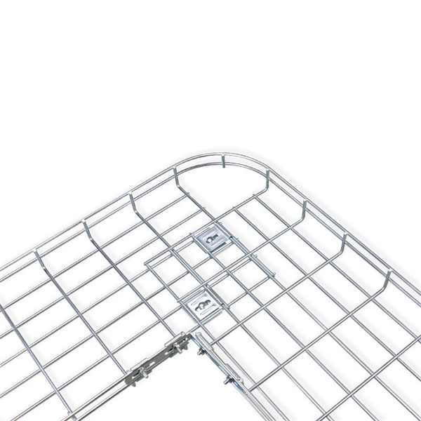
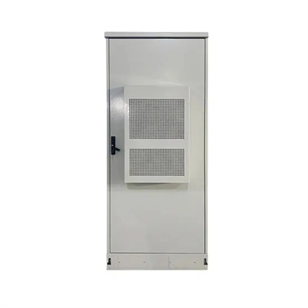
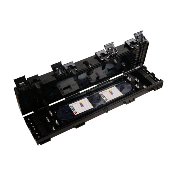
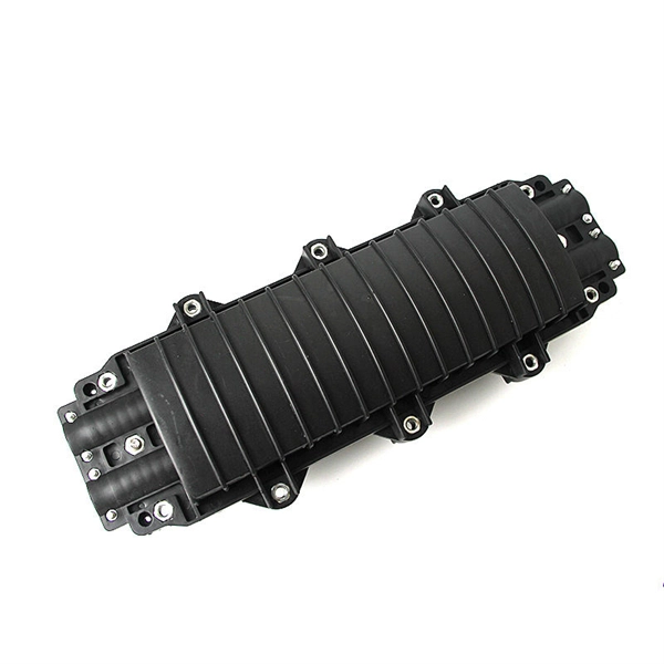
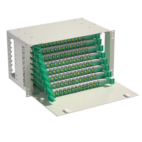
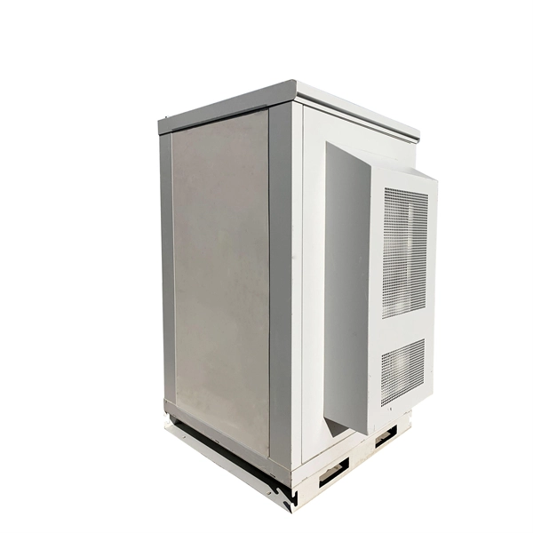
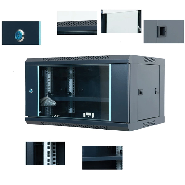
Learn how to install a fiber distribution cabinet step by step, including mounting, cable routing, grounding, and testing for FTTH networks. The installation of a fiber distribution cabinet involves five key steps: site selection, cabinet mounting, cable routing, fiber splicing, and grounding +. This step is very simple, we only need to install brackets on both sides of the optical fiber distribution box, and then fix the brackets to the designated position of the rack with screws. It should be noted that before installing the optical fiber distribution box, the installation direction of. Keeping this page as a placeholder for now. Have any questions? Talk with us directly using LiveChat. Read and understand this procedure (as well as the instructions provided with related assemblies) before beginning an installation. Do not discard this instruction; keep it on hand for future reference. Familiarize yourself to understand the unit's placement in your network. The 1U fiber optic distribution box is used as an example to introduce its structure. Three adapter panels can be installed on the front panel of this fiber optic distribution. Fiber Distribution Hub Installation Procedure - Optical Cable Corporation Products Fiber Copper Hybrid Cabinets, Racks, Enclosures Deployable Solutions Industries Oil & Gas Mining Industrial BroadcastAV Military Commercial Enterprise library & Support Contact Resources About OCC News Careers.
[PDF]
This paper describes a disruptive continuous monitoring system to detect Corrosion Under Insulation (CUI) risks for every meter of pipeline over large distances. Distributed Fiber Optic Sensing (DFOS) has emerged as a viable non-destructive ATEX-proof solution to detect CUI. ors by depositing metal coatings to the surface of the sensors. Three types of fiber optic sensors were investigated as candidates for corrosion detection: the extrinsic Fabry-Perot interferometer (EFPI), the absolute extrinsic Fabry-Perot interferomete (AEFPI), and the long period grating (LPG). This paper presents a distributed monitoring approach for detection, visualization, quantification, and warning for pipe corrosion using a single-mode telecommunication-grade fiber optic cable as a distributed sensor. The distributed sensor can be deployed on the surface of a pipe to measure. Fiber optic AE sensor was tested due to its anti-explosiveness, fitting to petrochemical plants. Experiment was successful, and one sensor could detect approx. 4,000mm-away corrosion. Our study attempts to detect. Experimental Investigation for Monitoring Corrosion Using Plastic Optical Fiber Sensors Liang Hou 1,*, Shinichi Akutagawa 1, Yuki Tomoshige 2and Takashi Kimura 2 1Department of Civil Engineering, Kobe University, 1 -1, Rokkodaicho, Nadaku, Kobe 6578501, Japan; cadax@kobe-u. jp 2Engineering.
[PDF]
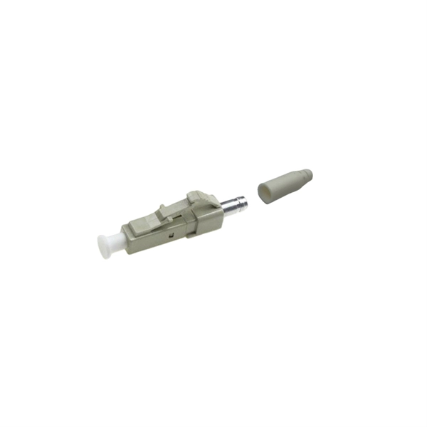
The QSFP28 transceiver provides 100GBase-BX throughput up to 20km over single-mode fiber (SMF) using a wavelength of 1310nmTx/1280nmRx via an LC connector. This bidirectional unit must be used with another transceiver or network appliance of complimenting wavelengths. Whether it's building a network or upgrading an existing network, the Cisco® QSFP-100G-B20U4-I and QSFP-100G-B20D4-I transceivers provide 100G connectivity for platforms at up to 20km on single SMF (Single Mode Fiber). This. The QSFP-100G modules are our latest generation of 100G transceiver modules solution based on a QSFP form factor. Table 1 describes the Cisco QSFP-100G portfolio. Cisco QSFP-100G Portfolio The Cisco 100GBASE-SR4-S QSFP Module supports link lengths of up to 70m. To meet the demand for long-distance transmission in scenarios where optical fiber resources are scarce in edge access networks, Walsun has launched the 100G QSFP28 ZR4 BIDI product, and will demonstrate 100G 80km single-fiber bidirectional service transmission at OFC 2024. 66nm-RX) via an LC. NEC's 100G QSFP28 BiDi optical transceiver enables the transmission and reception of 100Gb/s high-speed data over a single optical fiber. By enabling bidirectional transmission over a single fiber, this module enhances fiber utilization efficiency and can reduce fiber costs. ZR4 BiDi, using four.
[PDF]
In this guide, we list the Top 5 Global Manufacturers who set the standard for fire safety. We will also clarify the confusing jargon (OFNR vs. IEC 60331) and show you how to source safety-compliant cables without breaking your budget. Discover premium quality flame retardant fiber optic cable designed to enhance connectivity and performance. Ideal for business buyers seeking reliable solutions. From enabling the energy transition with our pioneering E-Path sustainable cable solution, to supporting critical telecom infrastructure, Prysmian plays a pivotal role in building resilient and efficient systems across the globe. Our commitment to work closely with our customers ensures that we. These indoor fiber optic cables are used exclusively within buildings and must have a flame-retardant cable jacket to fit this purpose. Flame resistant cable may be deployed in-duct (conduit) or cable tray. These essential components are designed to transmit data efficiently, offering reliability and speed in communication systems. The many types of communication cables each have a specific composition, design, and function.
[PDF]