OPGW (Optical Ground Wire) is a kind of cable that comprises the dual functions of grounding and fiber optic communication. It is increasingly utilized in high-voltage transmission lines as a functional element that both safeguards the power system and allows data sharing. OPGW cable in transmission line systems is a unique hybrid solution that combines the functions of grounding and communication into one efficient design. It typically consists of optical fibers encased within an aluminum or steel wire, providing both strength and data transmission capabilities. Enter Optical Power Ground Wire (OPGW) cables 1 —a technology that addresses these needs in a single, integrated solution. As someone who has spent years in the optical communications industry, I've witnessed firsthand how OPGW cables have transformed the landscape of power and telecommunication. An optical ground wire (also known as an OPGW or, in the IEEE standard, an optical fiber composite overhead ground wire) is a type of cable that is used in overhead power lines. An OPGW cable contains a tubular structure with. OPGW is primarily used by the electric utility industry, placed in the secure topmost position of the transmission line where it “shields” the all-important conductors from lightning while providing a telecommunications path for internal as well as third party communications. This guide explores its design, advantages, and applications in modern energy and telecom.
[PDF]
Recommendation ITU-T L. 89 describes the general requirements and a design guide for suspension wires, telecommunication poles and guy-lines that support aerial cables for optical access networks. This Recommendation also describes loads applied to the infrastructures. Aerial infrastructure. Teleworking, online games, online medical consultations, online education - all these services are enabled by fast fi bre optic broadband networks. The intent of such a. These cables vary significantly in material, construction, and application. The core composition and number of wire strands determine their strength, flexibility, durability, and resistance to environmental factors. Understanding the different types helps in selecting the right cable for. 40. FO-VC2 JOINT USE - VERICAL MIDSPAN CLEARANCES 48. FO-GB GROUNDING AND BONDING 49. APPENDIX A - COVER SHEET / TOC 52.
[PDF]
Tray cables (TC) are multi-conductor cables designed and rated for installation in cable trays and raceways or supported by messenger wires. Cable tray may be used as the Equipment Grounding Conductor (EGC) in any installation where qualified persons will service the installed cable tray system. There is no restriction as to where the cable tray system is installed. The metal in cable trays may be used as the EGC as per the limitations. maintain spacing or to keep cables in place when the tray is ect the minimum bend ra-dius for cables as they exit the bottom of the cable tray. A rung spacing of 6 to 9 inches (150 to 230 mm) is preferable when the cable tray cont d for instrumentation and control applications that require. The most frequently used tray cables are: Type TC – Tray Cable – (NEC Article 336) –Power and control tray cable type TC is a factory assembly of two or more insulated conductors, with or without associated bare or covered grounding conductors, under a non-metallic jacket. TC cables are rated for. Hubbell Wiring Device-Kellems and Hubbell Premise Wiring are divisions of Hubbell Incorporated, a U. headquartered manufacturer with over 130 years of supplying solutions for the electrical and data markets. At the panel, the cable is installed in conduit (s) for the vertical.
[PDF]
In this guide, we list the Top 5 Global Manufacturers who set the standard for fire safety. We will also clarify the confusing jargon (OFNR vs. IEC 60331) and show you how to source safety-compliant cables without breaking your budget. Discover premium quality flame retardant fiber optic cable designed to enhance connectivity and performance. Ideal for business buyers seeking reliable solutions. From enabling the energy transition with our pioneering E-Path sustainable cable solution, to supporting critical telecom infrastructure, Prysmian plays a pivotal role in building resilient and efficient systems across the globe. Our commitment to work closely with our customers ensures that we. These indoor fiber optic cables are used exclusively within buildings and must have a flame-retardant cable jacket to fit this purpose. Flame resistant cable may be deployed in-duct (conduit) or cable tray. These essential components are designed to transmit data efficiently, offering reliability and speed in communication systems. The many types of communication cables each have a specific composition, design, and function.
[PDF]
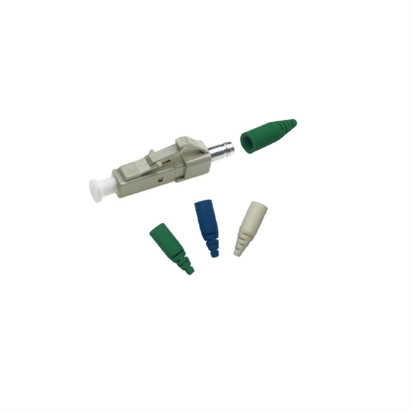
Get the wrong connector type, the wrong polish, or skip proper fusion splicing technique—and you're looking at elevated signal loss, increased back reflection, and a field termination that fails certification. Once you nail the logic chain— raw fiber → protected cable → spliced pigtail interfaces → flexible patching —you control loss budgets, installation time, and maintenance risk. Key takeaway: Treat the four items like a relay team. Each runs a specific leg so your network hits performance targets. In the intricate ecosystem of fiber optic networks, two components play a critical role in ensuring seamless connectivity: patch cords and pigtails. While both are essential for linking fibers to devices or other cables, they serve distinct purposes and are designed for specific scenarios. Executive Summary: A fiber optic pigtail is one of the most commonly specified yet least understood components in structured cabling. Despite their widespread use and numerous advantages, there are some circumstances in which they might not be the ideal option. A fiber optic pigtail is very practical for on-site terminations where fusion or mechanical splicers are used. Preterminated connectors offer several advantages over. Today, I'll show you how to pick the right patch cord or pigtail — step by step. A Fiber Patch cord connects two devices. You plug it into a switch, router, or patch panel. It's ready to use out of the box. A pigtail is for splicing.
[PDF]
This Technical Brochure describes the induction phenomena (inductive, capacitive and conductive) that can lead to presence of voltage and currents on disconnected cable systems. The optical fiber composite overhead ground wire (OPGW) has been widely used in power transmission lines. Methods of calculation to evaluate those values and touch voltages are detailed and analysed, associated with various. working on cables u al, photocopying, recording or otherwise, without the prior written or use by members of the Energy Networks Association to take account of the conditions which apply to them. Advice should. Literature review: An in-depth literature review covering the modelling and calculations of the conditions relating to faults caused by interactions between fibre optic cables and power cores in submarine cables. Examples of electrically conductive installations where induced voltage may occur could be: • Overhead lines or cables out of opera- tion •.
[PDF]
The vertical clearance for overhead fiber optic lines above the highway must be a minimum of 18 feet. The exception is ADSS cables which are approved for installation in the power space by qualified personnel. All aerial cables should be installed clear of any obstructions. The Fiber Optic Association, Inc. (FOA) was founded in 1995 to help develop the workforce to build the fiber optic networks to support a rapid expansion in communications and the Internet. The charter of the FOA was to promote professionalism in fiber optics through education, certification, and. The basic pole height is 7m and the tip diameter is 150mm. In case of special sections, crossing obstacles or roads or railways, the pole height of 8m, 9m, etc. can be selected according to the actual terrain. If the surface is stone, the depth needs to be 0. 9m, and if the surface is other soil. Generally a 12 inch to 24 inch soil separation is recommended as a safety barrier and for locating purposes. 9938 | SuperiorEssexCommunications. com Page 1 of 4 TECHNICAL GUIDELINE July 30, 2020 TG030 Rev. FIBER is used for relocating any fiber optic cable from one location to another. Field conditions will vary, so the actual location. to n utral comm.
[PDF]
Use this worksheet to input values for all variables that will impact your system's performance. After entering your values, please ensure you click the 'Calculate Link Loss' button at the bottom of the page to generate your total link loss. Add connectors, splices, bends, and safety margin easily. See results instantly above the form, then adjust values. Choose a mode, then enter values and optional losses. All calculations use base-10 logarithms. mW must be greater than zero. Used only in measured attenuation mode. Length is needed. The power budget refers to the amount of fiber optic cable plant loss that a datalink (transmitter to receiver) can tolerate in order to operate properly. Sometimes the power budget has both a minimum and maximum value, which means it needs at least a minimum value of loss so that it does not. To detect whether the link runs properly, the following calculation should be performed. It is often the case to calculate the maximum signal loss across a given fiber link during optical cable installation. First, you should be aware of the fiber loss formula: The Total Link Loss = Cable. Therefore, it is very important to calculate the fiber loss and take appropriate steps. In order to get the most reliable results, an Optical Time Domain Reflectometer (OTDR) trace of the actual fiber connection should be completed. This will provide you with the real.
[PDF]
The drop cable connects your home, the patch panel organizes the network, the splice keeps connections seamless, and the optical splitter shares the signal with your neighbors. The fiber drop cable is what makes a true fiber-to-the-home (FTTH) connection possible. It's the final link in the chain that ensures you're getting the full, unfiltered power of fiber internet, not a mix of fiber and older technology. From the street to your living room, every piece of the fiber. To begin, the standard definition of splicing in optical fiber is joining two fiber optic cables together. The other, more common, method of joining fibers is called termination or connectorization. Splicing is most commonly used in the field but has application in cable assembly houses. Infield. In many applications of fiber optics, it is necessary to connect fiber ends (terminations) in some way such that light from one fiber can get into the other fiber without losing too much of its optical power. This creates a permanent and low-loss connection. Both techniques have their advantages and are suited for different applications, but understanding which method to use can greatly impact the network's. Many installations involve splitting the fibers in a cable or dropping a small fiber count cable from a large backbone cable. Backbone cables of 144-288 fibers are common and larger ones are becoming more common too. Drop cables are often only 2-12 fibers, meaning most fibers are continuing.
[PDF]
We terminate fiber optic cable two ways - with connectors that can mate two fibers to create a temporary joint and/or connect the fiber to a piece of network gear or with splices which create a permanent joint between the two fibers. Proper connection of fiber optic cables is essential to harness these benefits fully, as even minor errors can lead to significant performance issues like signal loss. These terminations must be of the right style, installed in a. Running fiber internally involves extending this high-speed link from the service entry point to a centralized location, such as a dedicated media closet or network rack. This DIY effort is undertaken to maximize performance, improve aesthetics, or relocate the Optical Network Terminal (ONT) to a. In this video, we'll guide you through preparing and terminating fiber optic cables using SimplyFiber products, known for their high quality, ease of use, and reliability. more Audio tracks for some languages were automatically generated. Two types of splices are used in fiber optic cabling one is Mechanical the other is Fusion. Whether you're installing a new network, expanding an existing one, or. But here's the thing: how you connect fiber optic cable really matters. A shaky connection means weaker signals, dropped streaming, or slow uploads. Get the hookup right, and you'll enjoy streaming, gaming, and video calls without interruptions.
[PDF]
It is recommended to use tinned copper stranded wire with a minimum cross-sectional area of 4mm² for bridging, with tinned copper lugs crimped at both ends. Iron bolts welded at both ends of the cable troughs can rust and increase contact resistance. Cable tray may be used as the Equipment Grounding Conductor (EGC) in any installation where qualified persons will service the installed cable tray system. The metal in cable trays may be used as the EGC as per the limitations. Standard splice plates can often provide a safe electrical path if they are UL Classified and bolted tight. However, you must use copper bonding jumpers if the tray is painted or has expansion joints for movement. A. Cable tray wiring systems have excellent safety and dependability records. The intent of this article is to review grounding practices for cable tray. Snap Track Cable Tray Can be used as an Equipment Ground Conductor (EGC) Snap Track cable tray is UL Classified, marked with the available minimum cross sectional area and meets all requirements for use as an Equipment Ground Conductor per NEC Article 392. Standard Snap Track splices, tee's. What is best practice for terminating the ground wires within tray cable? Especially when you have a parallel tray cable feeder? For example: A parallel tray cable feeder is installed in cable tray to a 400 amp distribution panel.
[PDF]
Cable trays are used as an alternative to open wiring or electrical conduit systems, and are commonly used for cable management in commercial and industrial construction. In the electrical wiring of buildings, a cable tray system is used to support insulated electrical cables used for power distribution, control, and communication. Today, electrical cable trays have become an essential component in industrial and commercial construction, providing a quick, economical, and. -piece tray istypically used in applications where visual esthetics are important. It is used in a range of applications with sp nch runs from the main cable tray system to electr cal devices or other equipment. It is available with a ventilated or solid bottom. Channel tray can protect against. Cable trays support cable across open spans in the same manner that roadway bridges support traffic. Cable trays are not raceways, and are treated as a structural component of a facility's electrical system. A bridge is a structure that provides safe passage for traffic across open spans. The National Electrical Code publishes the standards for all.
[PDF]
This guideline defines the requirements and standards for design of underground electrical and telecommunication pathway systems. The guideline covers concrete encased duct banks and manholes for primary (medium voltage) power distribution cables and telecommunications. The UGS Manual provides guidance and standards pertaining to installing and working with underground structures for electrical facilities. Also included are. The purpose of this Distribution Standards manual is to provide the basis for standardized, uniform, and consistent engineering, construction and maintenance practices for the Nashville Electric Service (NES) system. The contents of this manual contain minimum requirements used in designing and. This section contains the requirements for equipment and installation (including manholes, switch vaults and pull boxes) relating to the Sub-transmission, Distribution, and Control of electric power ranging from 600-Volts to 25,000-Volts, such as substations, switchgear, circuit breakers, and. stent and reliable underground power distribution system. These standards are required to be used by anyone who is involved with design or installation of underground power distrib ion systems within the St. George City service territory. All high voltage, 600 volts or higher, underground power. FILING INSTRUCTION: This bulletin replaces RUS Bulletin 1728F-806, Specifications and Drawing for Underground Electric Distribution, dated June 2000.
[PDF]
Q: How far can multimode fiber go? A: The transmission distance of multimode fiber depends on the fiber type and data rate. OM3 and OM4 multimode fibers typically support up to 300m and 400m, respectively, for 10G Ethernet. At lower data rates, such as 1G Ethernet, multimode fiber. Multimode fiber optic cables are designed to carry multiple light modes simultaneously, each taking a different path or mode through the fiber. This characteristic makes MMF ideal for high-bandwidth applications over relatively short distances. Common applications include Local Area Networks. Fiber optic cable transmission distance is determined by two primary physical factors that affect signal quality as light travels through the fiber medium. The greater the distance, the greater. A: Single mode fiber can typically transmit up to 160 km, and with dispersion compensation, it can exceed 200 km. For most enterprise or data center applications using multimode fiber, the practical limit sits between 300 m and 550 m. However, the dispersion-compensating fibers can support more than 200 kilometers. How. For instance, without amplifiers, single-mode fiber can reach 50-60 miles and can support data rates of 1 Gbps or 10 Gbps. With amplifiers, such as Erbium-doped fiber amplifiers (EDFAs), the distance can be extended to 600 miles or more, and even further with additional amplifiers for long-haul.
[PDF]
Proper fiber optic termination is a crucial process for ensuring the reliability, performance, and long-term durability of any fiber optic network. The process of fiber optic cable termination is the essential act of connecting fiber optic cables to devices, patch panels, or other. Fiber optic joints or terminations - where cables are terminated - are made two ways: 1) connectors that mate two fibers to create a temporary joint and/or connect the fiber to a piece of network gear (left) or 2) splices which create a permanent joint between the two fibers (right). Thus, you will put the cable across the points, stretch it to determine length, cut it accordingly, and place the connector on each end. After that, the patch panel attaches to it. Each cable has a connector attached. A. Once fiber optic cables have been successfully placed, we can focus on managing the ends of the fibers. This process depends on the project's needs and identifying a solution that aligns with the current situation. We can make suggestions that typically benefit the current circumstances and result. Where copper twisted pairs tend to terminate with an RJ45 plug, fiber optic connectors come in all sorts of shapes and sizes, with all manner of different use cases in mind. An optical fiber connector is used to join optical fibers where a connect/disconnect capability is required.
[PDF]