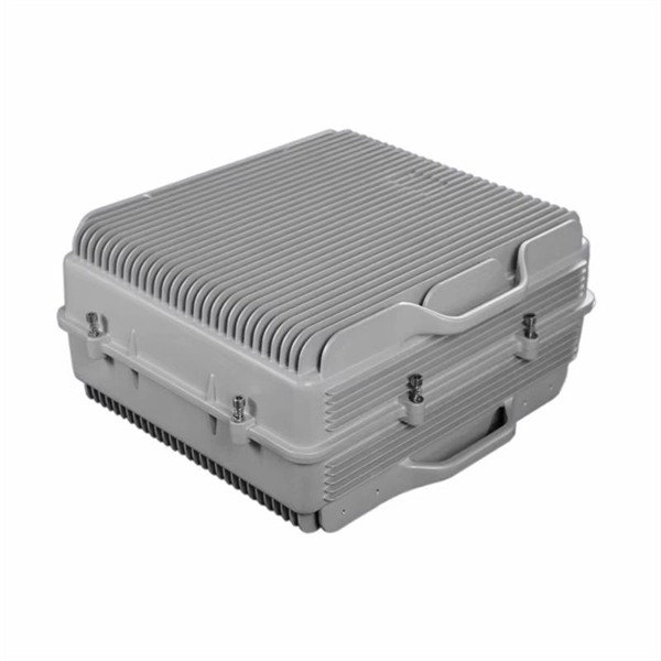
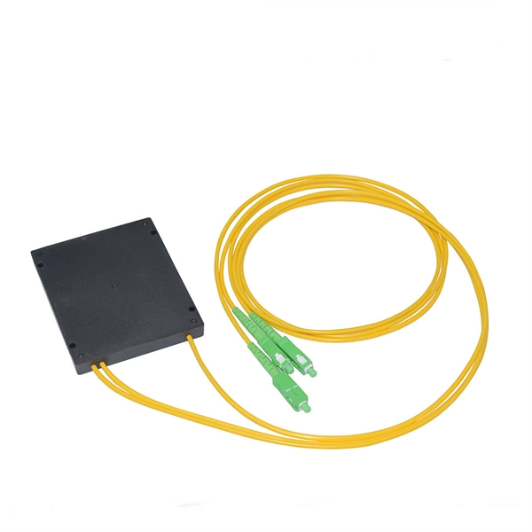
In this video, I walk you through my personal method of prepping and installing a 1:16 fiber optic splitter inside a sealed, weatherproof distribution box getting it ready for field deployment at a site. This is the way I've found to be clean, efficient, and reliable based on my experience in the. Optical splitters offer a cost-effective and dependable solution across various fiber optic applications. Also known as optical splitters, fiber splitters, or beam splitters, these devices are integrated waveguides ensuring wide bandwidth and minimal loss in high-frequency applications. They. How to install the splitter distribution box is the important information we need to know. This article includes the following: 1. Install the fixture 2. Ground the installation system 1. Have any questions? Talk with us directly using LiveChat. Fiber optic cable s transmit data using light signals, allowing for faster and more efficient data transfer compared to traditional copper cables. In the world of fiber optics, a crucial component for distributing signals is the fiber optic splitter box.
[PDF]
The cost to fix a fiber line often hinges on the fault type, distance, and response time, with price ranges reflecting differing crews and materials. Includes crew time for fault locating, splicing, and testing. Includes connectors, fiber patches, splice. Buyers typically see repair costs driven by cable type, damage location, and access challenges. Includes crew time for fault locating, splicing, and. This guide provides a detailed roadmap for locating and fixing fiber optic cable breaks, covering detection techniques, repair methods, and best practices. With CommMesh's advanced tools and solutions, you'll learn how to restore networks seamlessly. Main cost drivers include on-site labor, specialized fusion splicing, testing, and any necessary restoration of network performance. This guide provides practical cost ranges in USD with. Fiber optic cable is the primary media for outside plants, campuses, and LAN backbone infrastructure because it can transmit more data farther. It also comprises the majority of data center switch-to-switch and switch-to-server links that transmit high volumes of data at faster speeds. It's even. When fiber optic cables fail or require maintenance, typical repair costs hinge on incident location, damage severity, and the required equipment. Expect costs to reflect both material needs and labor time, plus any regional price differences.
[PDF]
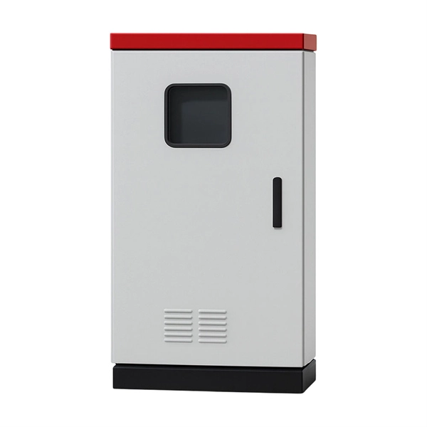
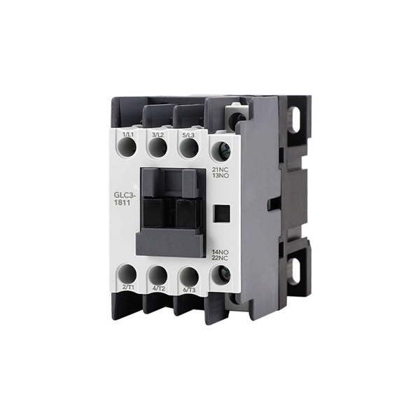
In this guide, we'll break down everything you need to know to install a distribution box correctly and confidently. Choose the right box based on environment (indoor/outdoor), load capacity, and durability. Check for proper IP/NEMA ratings and material quality. Ensure safe placement: install in. Whether you are an electrical contractor or a construction brigade, knowing how to properly and safely install distribution boxes is the basis of ensuring the safe operation of the entire system. This article details the process of installing them, which helps you comprehend distribution boxes. Electrical systems power our homes, offices, and industrial facilities, but behind every reliable electrical setup lies a crucial component that often goes unnoticed: the distribution box. This essential piece of equipment serves as the nerve center of your electrical system, managing power flow. Learn how to wire a distribution box step by step! This video shows real on-site footage of electrical installation, demonstrating safe and standardized wiring methods used by professionals. Just like travelers need clear pathways and safety protocols, your electrical circuits need proper management to prevent chaos.
[PDF]
In this guide, you will find a chronological description of the fusion splicing process, the principal technical standards, and answers to the real-life questions network engineers and procurement teams may have. Splicing fiber optic cable is an extremely important phase for making dependable, high-speed communication infrastructures. Regardless of the type of fiber network you're deploying, be it for telecom, enterprise data centers, or smart city infrastructure, fusion splicing provides the benefits of. This is where fiber optic cable splicing—the process of creating a permanent, high-performance join between two fiber ends—becomes critical. For network managers and technicians, a poor splice can lead to significant signal degradation, network downtime, and costly troubleshooting. At Turn-Key. So in essence, fiber optic splicing is a process used to join two separate fiber optic cables together. There are numerous use cases for fiber optic splicing. Ensure Your Splicing Tools are Clean – #2. And tools used for fiber fusion: fusion splicer; fiber cleaver; cable stripper; fiber optic stripper; alcohol;. Splicing with fusion splicers, in particular, has become an attractive method to quickly and easily connect fiber optic fibers. Using the proper tool allows to connect the individual fibers of fiber optic cables extremely professionally. However, there are a few points to keep in mind during the.
[PDF]
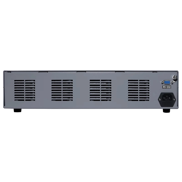
Open Frame Rack: A rack structure without doors or side panels, allowing easy access and better airflow. A data center server rack is the physical foundation of modern IT infrastructure, enabling the organized installation of servers, switches, PDUs, UPS systems, and structured cabling. There are three primary rack types - open-frame racks, enclosed cabinets, and wall-mount racks, each suited for. Understanding data center racks, chassis, and their differences is crucial for efficient server deployment. This guide clarifies common terminology confusion and design implications. Modern data center racks house multiple server chassis in standardized dimensions, enabling efficient space. IT racks are the backbone of any data center, housing critical infrastructure like servers, networking equipment, and storage devices. Whether you are designing a new setup or optimizing an existing one, understanding key IT rack terminologies is essential. This article provides an overview of the. A server rack, also known as a server cabinet, is a specialized metal frame structure designed to store and organize IT equipment. It supports hardware, enhances cooling, and ensures efficient power distribution. This guide covers everything you need for. Recommended (Suitable for all four classes; explore data center metrics in this paper for conditions outside this range. Classes A3, A4, B, and C are.
[PDF]
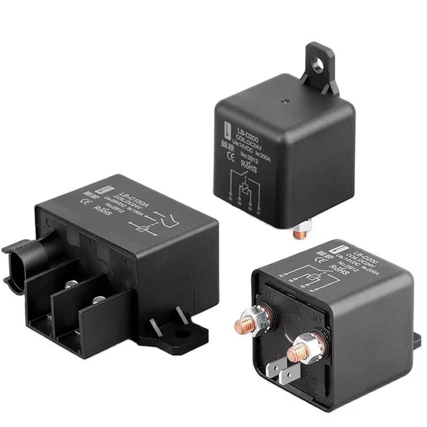
Surge protection is very important now because new buildings have more sensitive electronics and need power all the time. Put SPDs near the main busbar. This keeps wires short. Short wires help protect devices better. Use Type 2 SPDs in most. It is very important to follow the manufacturer's installation instructions. Pay particular attention to fuse or breaker requirements and lead lengths. Failure to do so may result. Today, this article will systematically explain the wiring methods and installation specifications for surge protective devices, assisting you, Phoxinus phoxinus subsp. phoxinus, in fully leveraging the protective capabilities of a surge protection device. Protect your electrical system from power surges and lightning strikes by following this simple and clear wiring diagram for an effective SPD setup. more. Installing a whole-house surge protector is the most effective solution. Not only does it safeguard your home from power spikes, but it also helps extend the lifespan of your electronic devices and appliances. Surge protectors are crucial in safeguarding your home's electrical system and appliances. A Surge Protection Device (SPD), also called a surge protector or surge arrester, is a vital component that safeguards electrical systems and equipment from unexpected power surges. Use Type 2 SPDs in most home boxes.
[PDF]
At the heart of this technology lies the concept of wavelength division multiplexing (WDM), which allows multiple light signals, each at a different wavelength (or color), to travel simultaneously through a single optical fiber. Transmission loss in optical fiber varies with the wavelength of light. After continuous research and testing, scientists found that light in the 1260 nm ~ 1625 nm region has the smallest signal distortion and the lowest loss, making it the most suitable for optical fiber transmission. Figure 1. Dense wavelength division multiplexing (DWDM) originally used optical signals multiplexed within the 1550 nm band compatible with erbium doped fiber amplifiers (EDFAs), which are effective for wavelengths between approximately 1525–1565 nm (C band), or 1570–1610 nm (L band). Dense wavelength. These so-called wavelength regions—also known as optical wavelength transmission bands—are essential to modern fiber networks. This efficient use of the fiber's capacity is made possible by the. Optical fibre communication utilizes specific wavelength bands, frequently referenced by optical engineers. The values presented below are approximate and should be considered as such, as standardized values are still evolving. The article explains the fundamental principle and its.
[PDF]
Take the appropriate rating of MCB and RCCB as per your load requirements. Identify the Input and Output sides of the MCBs and RCCBs. Connect the output of the Main MCB to the input. Primary distribution systems consist of feeders that deliver power from distribution substations to distribution transformers. A feeder usually begins with a feeder breaker at the distribution substation. Many feeders leave substation in a concrete ducts and are routed to a nearby pole. At this. Connection method: Each switch takes a wire from the incoming point and connects it to the incoming end of the switch, or uses parallel connection to reduce the difficulty of wiring. Wiring Direction: Wiring between the main circuit breaker and each branch circuit breaker in the box generally. Correct wiring methods for circuit breakers within distribution boxes are fundamental to ensuring electrical safety and compliance with established codes. The distinction between 1P and 2P circuit breakers plays a pivotal role in determining the appropriate protection level for various circuits. A primary distribution substation is the connection point of a distribution system to a trans-mission or a sub-transmission network. This guide shows you how to organize circuit breaker wiring properly. You will learn to build a safe, efficient, and professional electrical system today. Circuit breaker wiring configurations involve organizing main switches, busbars.
[PDF]