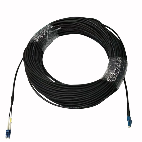
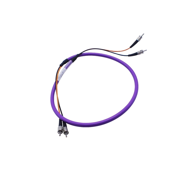
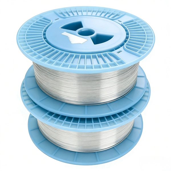
Typical project ranges for fiber optic cable per meter span from a low of roughly $0. 65 to a high around $5. 00, depending on type, protection, and installation needs. The majority of projects cluster in the $1. 60 per meter range for standard indoor runs with simple. Fiber optic cable cost per meter varies by type (single‑mode vs multi‑mode), durability, and installation conditions. The main price drivers include cable grade, jacket material, pull tension, connectorization, and any required conduit or protection. The following coverage gives a practical price. Fiber-optic cable materials typically cost $1 to $6 per linear foot, depending on fiber count and cable type. Commercial building installations with 100-200 network drops generally range from $15,000 to $30,000. The type of fiber optic cable selected based on your requirements, length of installation, and number of fiber. Getting accurate cost estimates is crucial for winning fiber installation bids. Smart contractors know that underground vs aerial installation pricing varies wildly based on location and project conditions. We'll show actual costs for.
[PDF]
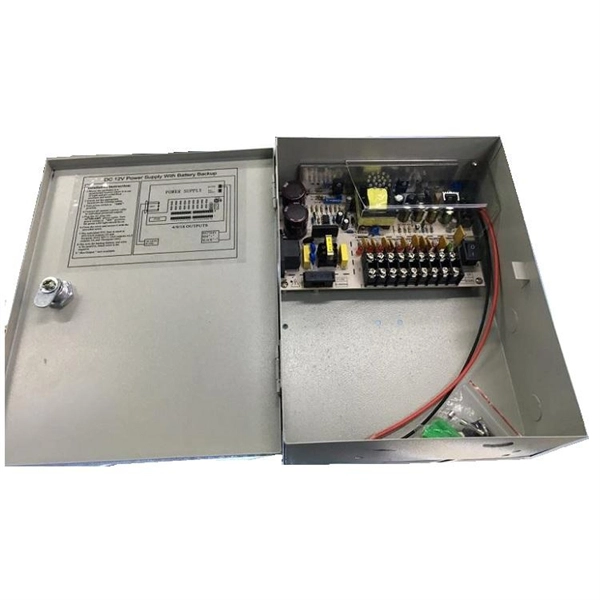
The primary function of a feeder wire is to facilitate bulk power transfer from a central source to a subpanel or a secondary distribution center. An example is the large cable running from the main service panel to a subpanel in a detached garage, basement, or workshop. A main panel and a sub-panel are both important components of an electrical distribution system. It is usually located where the main electrical service enters the building, often on an. Main feeder wires are the arteries of a building's electrical system, designed to safely and efficiently transport a large volume of power from the service entrance to secondary distribution points. They form the backbone of the electrical distribution network, handling the substantial current. An electrical sub panel, also known as a sub distribution board or sub circuit breaker panel, is a smaller secondary panel connected to the main electrical panel in a building. It serves as an extension of the main electrical panel to distribute power to different areas or circuits within a. Distribution board is a safe system designed for house or building that included protective devices, isolator switches, circuit breaker and fuses to safely connect the cables and wires to the sub circuits and final sub circuits including their associated Live (Phase) Neutral and Earth conductors. The distribution box acts as the center of power distribution, distributing electricity to all connected devices.
[PDF]
This guide provides cost estimates in USD with low, average, and high ranges and explains what drives these prices. Assumptions: region, service call for electrical work, permit requirements, and box type vary by locality. The total project range typically falls between $1,500. How much does it cost to replace an outside electrical meter box? Get free estimates for your project or view our cost guide below: Electric meter box replacement costs $500 to $2,100 on average, depending on the meter size, location, installation complexity, and code requirements. New outside. Homeowners typically pay a lump-sum for electric meter installation ranging from modest upgrades to full service upgrades. The main drivers are meter type, service size, local permitting, and whether utility work is required. The price range below reflects common U. scenarios and includes both. Replacing a home meter box typically costs between US $500–$2,100, though large or complex jobs — like 400-amp or full service upgrades — may reach $5,000+, depending on wiring, permits, and labor. Professional installation ensures NEC compliance, proper grounding and bonding, and successful inspection approval. Cost ranges reflect total project price plus typical per-unit components.
[PDF]
Optical modulators are used in optical communication systems to encode data onto light waves for transmission through optical fibers. The modulator encodes the data onto the light wave by modifying its amplitude, phase, or frequency. 📦 For purchasing, use the RP Photonics Buyer's Guide for optical modulators. It provides an expert-curated supplier directory, buyer-focused technical background information, and structured selection criteria to support professional procurement decisions. What are Optical Modulators? An optical. Optical modulators are devices that modify the properties of light, such as its amplitude, phase, frequency, or polarization, in response to an external signal. These devices play a crucial role in modern optics and photonics, enabling the manipulation of light for various applications. The beam may be carried over free space, or propagated through an optical waveguide (optical fibre). It acts as the “translator” between the electronic and photonic worlds. They enable the modification of optical wave characteristics such as the intensity, phase, polar-ization, and frequency of light signals. There are basically two types of modulators: bulk and integrated-optic.
[PDF]
As shown in the figure below, the main cable consists of three conductor wires extending from the top of the motor flat lead extension to the wellhead banded to the production tubing. The ESP cable carries current (amperage) from the motor controller at the surface down to the motor. CAVALCADE™ ESP power cable meets the high-quality standards required for any oil and gas industry specification–even the most challenging unconventional applications–to deliver the electrical requirements of your ESP and to extend system run life. Get cable built with solid copper conductors. Typically, it is banded or clamped to the production tubing from below the wellhead to the ESP unit because it is not designed to support its own weight. It is a specially constructed three-phase power. Levare is one of few artificial lift equipment providers manufacturing the complete ESP system including power cable. The total facilities capacity is approximately 10,000 kilometers (over 6,200 miles) of power and motor lead extension (MLE) cables annually. It is a specially constructed three-phase power cable designed. When performing well interventions, the choice of a suitable cable is critical to ensure well control is maintained while deploying wireline through pressure control equipment (PCE). Depending on the well conditions, many considerations should be taken into account for choosing the best cable.
[PDF]
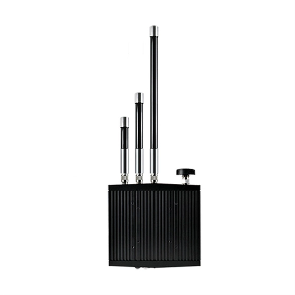
The optical fibre sensors are divided into two categories: thrubeam and reflective. The thrubeam type comprises a transmitter and a receiver. The reflective type, which is a single unit, is available in 3 types: parallel, coaxial, and separate. The fibre optic sensor has an optical fibre connected to a light source to allow for detection in tight spaces or where a small profile is beneficial. The light beam travels through the core by. Fiber optic sensors are prevalent in various applications, from computers and printers to motion detectors. For instance, when a printer or copier door is open, light falls on the sensor, stopping the machine for safety. Fiber optic sensors use light properties to detect and measure physical quantities such as temperature, pressure, and displacement. Depending on the application scenario, different. Functional (all optical fiber type) optical fiber sensor Using optical fibers (or special optical fibers) with sensitivity and detection capabilities for external information as the sensor element, the sensor combines "transmission" and "sensation". During operation, the light source enters the optical modulation region through the incident fiber. The physical quantity to be measured (such as.
[PDF]
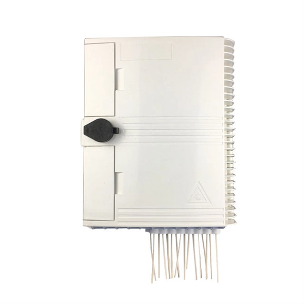
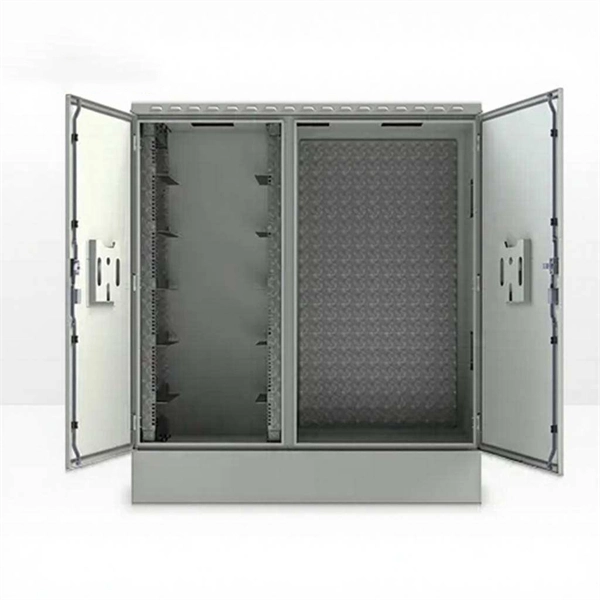
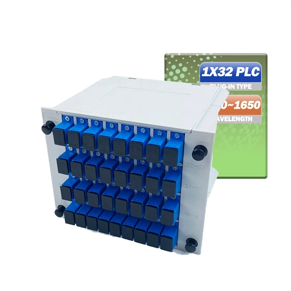
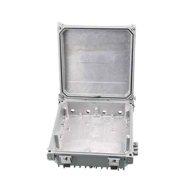
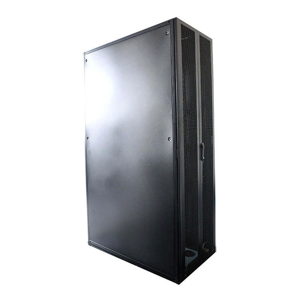
Fiber distribution box, also known as fiber optic distribution frame, is an essential component in fiber optic communication networks. It plays an important role in organizing, managing, and protecting fiber optic cables, ensuring reliable and efficient network operations. With features like IP68 waterproof ratings, fast connectors, and hardened adapters, distribution boxes enhance data transmission by offering proper termination points and environmental protection. It provides a secure space where incoming fiber optic cables from the provider's network are. A fiber distribution cabinet is a key component in modern fiber optic networks, designed to manage, protect, and distribute optical fibers efficiently. It serves as a central point where fiber cables are terminated, spliced, and organized for further connection to end users. The distribution box provides.
[PDF]
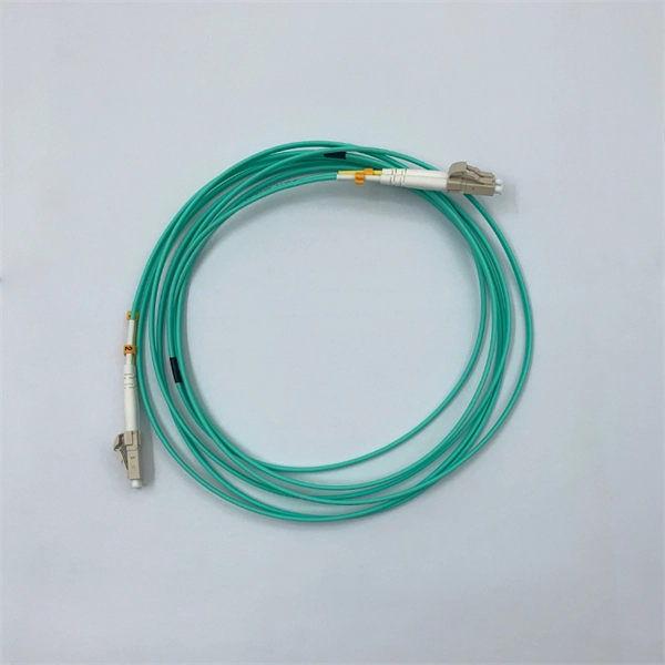
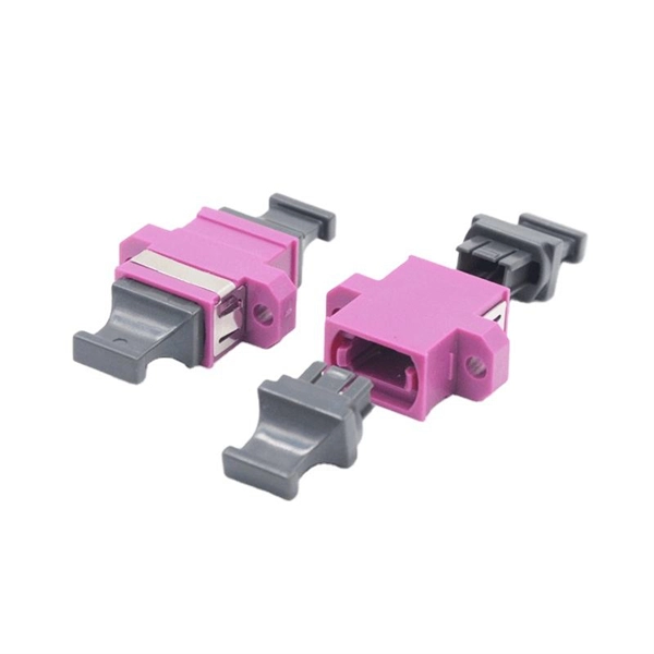
Summary : Fiber optic color codes are crucial for efficient, accurate, and reliable network installations. This guide explains how standardized fiber strands, cable jackets, connectors, and MPO systems simplify identification, prevent mismatches, and maintain signal. Tired of sorting poorly colored fibers? WolonFiber's 12-Color Fiber Optic Pigtail Packs are manufactured strictly to the TIA-598-C standard with vibrant, easy-to-identify colors. Perfect for fast, error-free termination in your ODF or splice closures. Following industry. You'll learn how to identify single-mode vs. multimode at a glance, trace individual strands in a 144-fiber bundle, and avoid the critical error of mixing connector types. In fiber optics, color isn't for decoration; it's a critical safety and efficiency tool. The TIA-598 standard (specifically. While labeling text offers specific details, color-coding makes it easy to identify cable uses or zones. In accordance with TIA-598-D standards fiber optic cables are based on the standard colors for jackets in single-mode: yellow, aqua/orange for multimode. 3 Create your own standards using colored.
[PDF]
Diode lasers are compact, solid-state devices that generate coherent light from semiconductor material. They are constructed using materials like gallium arsenide (GaAs) or gallium nitride (GaN). SEM (scanning electron microscope) image of a commercial laser diode with its case and window cut away. The anode connection on the right has been accidentally broken by the case cut process. They operate by applying an electrical current to the semiconductor material, which stimulates the. What is a Laser Diode? A laser diode is a small, solid-state equipment that uses semiconductor material to produce continuous light. The laser can be made up of a single diode or a combination. Laser diodes come in various types, each suited for specific applications. The most common types include: Single-Mode Laser Diodes: Emit a single wavelength of light, ideal for high-precision tasks. VCSEL. The laser diode is a form of semiconductor diode that generates coherent laser light rather than the more usual incoherent light produced by other sources such as LEDs or other emitters, even though some of these produce a narrow band of frequencies. Semiconductor laser diode technology is in. The term LASER stands for Light Amplification by Stimulated Emission of Radiation. It functions similarly to an LED, but the key.
[PDF]
This chart guides how close workers can safely get to energized equipment based on system voltages and other factors, ensuring compliance with safety standards such as NFPA 70E. A distribution box, also known as a distribution board or panel, is the central unit that distributes incoming electrical power to various circuits. Each outgoing line can be individually. Working space: The front clearance, side clearance, and height clearance requirements for electrical equipment that provide a safe area for maintenance, inspections, and other work. Dedicated space: The space equal to the width and depth of electrical equipment in addition to the space extending. The National Electrical Code (NEC) provides comprehensive safety standards for electrical installations, including requirements for electrical panels (main service panels and subpanels or breaker box). NEC Article 408 covers switchboards, switchgear, and Panelboards installation and applications. Electrical clearances set the minimum safe distances for panels, overhead lines, pools, and buried wiring — and ignoring them has real consequences. They would have done better to use an LB or a gutter. The problem is the box has a rated fill and the wire has a bend radius. Maintaining a safe working distance from energized parts in electric power systems is critical to preventing electrical.
[PDF]
Absolute optical power calibration of optical power meters, radiometers and photodiodes: From 350 to 1650 nm in 5 nm steps, power range +10 to -60 dBm / 10 mW to 1 nW, with least uncertainty of 0.06 dB.
[PDF]
Slide the electric meter into its slot in the box. Make sure it's seated properly and lines up with the mounting mechanism. Once aligned, lock or secure it into place to prevent movement or tampering. This step is especially important if your meter is installed outdoors. energy meter connection with distribution box How to Connect an Energy Meter to Your Distribution Box Easily Steps to Properly Connect Your Energy Meter to a Distribution Box. Inside the service housing, line conductors from the utility feed typically enter through the. An electric meter box wiring diagram is a visual representation of the electrical connections and circuits involved in connecting an electric meter to the rest of the electrical system in a building. The diagram provides a clear and concise overview of how the meter is connected to the electrical. The process of connecting a meter socket to a main breaker panel involves the installation of service entrance conductors, which carry the full electrical load and voltage from the utility supply into a building. Following is the figure and the steps that you need to follow while wiring a meter socket: Figure 1: Meter Socket Wiring. When it comes to the electrical system in a building, one of the crucial components is the wire that connects the meter to the breaker box. It plays a vital role in.
[PDF]
Provides accurate and cost-effective testing methods for the optoelectronic signal testingand anomaly simulation of high-speed optical transceiver modules. The OptoBERT™ OPB04X10 is the industry's most compact, cost-effective, easy-to-use 4-channel 10Gbps electrical bit-error-ratio tester (BERT). PBT3058 is a high-performance Bit Error Ratio Tester which can be used for physical layer characterization and consistency test of high-speed serial signal. 6TBASE/CEI-224G standards and also supports PCIe rate testing ranges through extended rate. Transmitter net measurement:. Our portable and stationary provers ensure accuracy and industry compliance for flow meters on a variety of in the field applications. Available in custom configurations and max flow rates, each prover is designed to eliminate the many prover problems of the past including our Unidirectional. In high-speed digital communication systems, even the smallest bit-level error can compromise performance, reduce efficiency, or lead to costly rework. That's why Physical Layer Tech offers precision-engineered Bit Error Rate Testers (BERTs) designed to verify data transmission accuracy and ensure. Whether you are looking for the smallest handheld 100G bit error rate tester in the world for your field job, or perhaps your needs take you into the lab, VIAVI has you covered with our accurate and easy-to-use BERT equipment for any use case. · Use control board and replaceable.
[PDF]
This video illustrates the step-by-step connection from the energy meter (KWH Meter) to the main Double-Pole MCB, the Neutral Link terminal block, and finally to the four individual Single-Pole Miniature Circuit Breakers (MCBs) for distribution to different circuits. In this guide, we will break down the key elements involved in connecting the main power supply to your home, providing a clear path for a successful setup. We will focus on the critical parts of the system, from basic components to step-by-step assembly procedures. Whether you are looking to. Always begin with disconnecting the main supply before accessing any enclosure containing distribution components. This prevents arc faults and ensures safety when modifying or inspecting current paths. Inside the service housing, line conductors from the utility feed typically enter through the. When it comes to electrical wiring, the connection between the meter and breaker box is crucial. This connection ensures that electricity is properly distributed throughout the building, allowing appliances, lights, and other devices to function. It shows the hot wire entering the meter lugs, the neutral wire connecting to the neutral bus bar, and the essential ground wire linkage to ensure system safety. Watch a simple and clear demonstration of how to wire a basic residential electrical setup. The diagram provides a clear and concise overview of how the meter is connected to the electrical.
[PDF]
An optical power meter is an electronic device that measures the power of an optical signal. It helps engineers verify the performance of optical fiber systems, ensuring that the signal strength meets requirements, and is an essential tool for communication network maintenance and. An optical power meter (OPM) is a device used to measure the power in an optical signal. Other general purpose light power measuring devices are usually called radiometers, photometers, laser power meters (can be. An optical power meter (OPM) measures the power levels of light signals in devices that transmit data or power using light. The term "optical power meter" may sound generic, but in popular usage, it specifically implies a fiber optic power meter. For light power measurements outside the field of. Optical Power Meters (OPMs) are crucial instruments in the field of optical sensors and fiber optic communications. It provides an expert-curated supplier directory, buyer-focused technical background information, and structured selection criteria to support professional procurement decisions. It measures optical power directly, and it is also used in loss testing when paired with a stable light source.
[PDF]