Check the diagnostic information, which shows that the received optical power is low, with a threshold of -3 to -23. 01, currently at -22. Once it exceeds the threshold, an alarm will be triggered. Troubleshoot the link, and if the link is normal, replace the optical. Run the display interface transceiver verbose command in the user view to check whether the transmit optical power (Tx Power) of the interface is within the allowed range. If yes, collect alarm, log, and configuration information, and contact technical support personnel. If the optical module is. An optical module was faulty. Cause 2: Output Optical Power Too High. Services on the optical module may be affected, which may cause bit errors, error packets, or even service interruption. During use, reading optical module information helps understand its real-time operating status, enabling faster troubleshooting of link abnormalities. The following uses the. The International Photonics & Electronics Committee (IPEC) is an international standards organization that is committed to developing open optoelectronic standards and delivering strategic roadmap reports. IPEC focuses on standardizing solutions in optical chips, optical/electrical components, and. The optical module on the port generates an alarm. Often referred as I²C, I2C, IIC (Inter-Integrated Circuit), MDIO (Management Data Input/Output) or CMIS (Common Management Interface Specification), these serial bus.
[PDF]
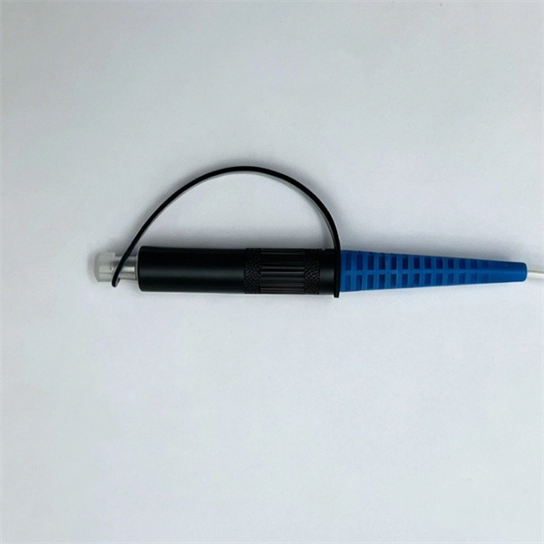
The most common and effective solution is the preformed tension clamp. This fitting consists of a set of helical rods that are wrapped around the cable, a thimble (clevis), and an extension link. The helical rods are designed to transfer the tensile load from the cable to the anchor. The function of the remaining cable rack is to store reserved optical cables, which are generally used on tensile towers (poles). There are two types: Inner button and outer disc. When the remaining cable rack is used for installation on the iron tower, it is equipped with two small splints. Additionally, adapters are available for the steel towers and steel and concrete poles. maintain alignment of and. ficing corrosion resistance. It is best suited to applications with moderate to low span ut increasing fibre strain. 3mm2 RRU Power cable. Without additional adapters, these clamps can provide sturdy, reliable, long-term support to systems. We manufacture a wide range of hardware fittings for OPGW Optical Ground Wire, including Suspension and Tension Assemblies, Down Lead clamps, Earthing Clamps, Splice Enclosure, Reinforcing Rods, Vibration Dampers, etc. Find many great new & used options and get the best deals for 5x Huawei Optical Cable Fixing Clamp 2x3 C Type Bracket Cable Clamp 27150086 at the best online prices at eBay! Free shipping for many products!.
[PDF]
Use the command display transceiver to view the optical module information of all optical ports, and use the command display transceiver interface interface-type interface-number to view the optical module information of a specific optical port. Related Information Video Identify a Huawei-Certified Optical Module Run the display transceiver [ interface interface-type interface-number | slot slot-id ] [ verbose ]. Here is an example on how to query or display optical power of an interface in a Huawei Router. This is tested using NetEngine40E Universal Service Router or NE40E running version 8. The specific viewing information is as follows:. Optical modules are widely used in switches, network interface cards (NICs), routers, and other communication devices. During use, reading optical module information helps understand its real-time operating status, enabling faster troubleshooting of link abnormalities. Transceiver Type : 1000 _BASE_SX_SFP Connector Type :LC Wavelength(nm) : 850 Transfer Distance(m) : 300 (50 um), 150. We want to troubleshoot transceiver on Huawei router, Huawei switch, Huawei systems. 1 Show details, warning etc. from transceivers Check “Alarm information” section for warnings, LOS Alarm means no inbound signal, execute display this to check shutdown mode, execute undo shutdown if necessary.
[PDF]

The actual number of optical modules used primarily depends on the following factors. Discrepancies in Calculating the Ratio of Optical Modules to GPU-The Varying Usage Quantity Due to Different Networking Architectures. Network Card Model. GPUs such as the A100, H100, and upcoming GH100 require high-speed optical interconnects to link thousands of GPU nodes, enabling large-scale AI model training and inference. Network Card Model It mainly includes two network cards, ConnectX-6. Traditional optical transceivers, especially in 400G and 800G deployments, generate significant heat and demand substantial power just to keep the lights blinking. 1) NIC Models Mainly includes two types of network cards, ConnectX-6 (200Gb / s, mainly used with the A100) mainly used optical modules are MMA1T00-HS (200G Infiniband HDR QSFP56 SR4 PAM4 850nm 100m) and ConnectX-7. Two complementary approaches are used to grow these systems: scale-up (tightly coupling many accelerators as one unit) and scale-out (networking multiple units across racks or clusters). In both cases, optical connectivity is playing an increasingly vital role. Below, we explain the trends in. While the industry-standard OSFP (Octal Small Form-Factor Pluggable) module has successfully enabled 400Gbps, 800Gbps, and 1. 6Tbps optical pluggable modules , it is limited to 32 modules per Rack Unit (RU), typically requiring 2 RUs to achieve 102. 4Tbps and 4 RUs to reach 204. 8Tbps of switching.
[PDF]
Use this selector tool to quickly identify the best power supply for your aerospace and defense ATE requirements. Explore engineer-authored content and a vast knowledge base with thousands of learning opportunities. Use 25+ X-Series applications to analyze, demodulate, and troubleshoot signals across wireless, aerospace/defense, EMI, and phase noise. With extra memory and storage, these enhanced NPBs run Keysight's AI security and performance monitoring software and AI stack. Achieve fast, accurate board-level. Fiber-optic switches control light paths within fiber optics, ranging from simple on/off types to complex matrix configurations like 64×64. Fiber-optic switches are optical switches in the context of fiber optics. They're a core component in fiber-optic networks, where data travels as pulses of light through glass fibers. This technology allows for high bit rate transmission to be switched between various optical lines. All of these optical switches are purely optical path, there is no optical to electrical to optical conversion. Click to jump to class of switch --- Provides a bypass of.
[PDF]
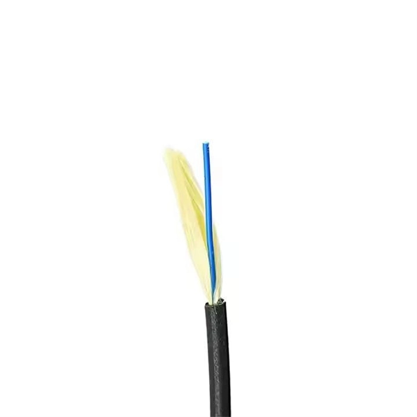
Yes, fiber cables can be bent during installation, which proves particularly useful when you pull cables into position rather than using blown installation methods. Blown fiber installation uses air pressure to propel cables through conduits, minimizing bending stresses. Fiber optic cables are designed to withstand some bending, but excessive bends can physically damage the glass fiber or cause significant signal loss. That's why every fiber cable has a minimum bend radius specification provided by the manufacturer. The minimum bend radius defines the smallest. All fiber optic cables have specifications that must not be exceeded during installation to prevent irreparable damage to the cable. Installers must understand these specifications and know how to install cables without. The bend radius of fiber cables is critical for maintaining high performance and longevity. A practical single-mode fiber option for compact routing, dense fiber management, FTTH access, and reel-based systems such as drone fiber and FPV fiber tether where bend-loss control matters in real installation and maintenance conditions. The tighter the bend, the smaller the radius. The minimum bend. Astel 4 Core Siamese model has 2 x 2 Fiber cables joined in the center by steel messenger. Its main advanctage is that a single cable can be used for 2 independent telecom operators. The optical fiber is made of high pure silica and.
[PDF]
Are you purchasing a new router or upgrading an old one? Use this tool to find the router that fits your needs. Juniper's single-box Packet Optical convergence solutions help operators simplify operations, lower transport costs, and tap new revenue opportunities. The ACX5400 Series of 1U routers provide power-efficient metro aggregation and support full IP/MPLS functionality. They deliver the performance. AI readiness comprises six pillars: Strategy, Infrastructure, Data, Governance, Talent, and Culture. Is your organization AI ready? Build the bridge between business outcomes and technology with our new interactive tool. Provide outsourced IT and consulting services with a broad technology. Whether you're upgrading enterprise Wi-Fi or need a high-performance enterprise wireless router, finding the right fit is essential. At Meter, we know how important it is to choose a router that delivers on performance, security, and scalability. That's why we've curated this guide to the best. The Huawei FTTR-SME OptiXstar B50 can function an intelligent optical network hub for SMEs by providing converged network, cloud, security, video, and computing services. It can be used to build secure, reliable, ultra-high bandwidth, and ultra-high concurrency all-optical Wi-Fi networks for SMEs. For SMBs, enterprise routers offer. Milesight helps customers in buildings, retail, healthcare, education, and more achieve their goals smarter and faster. Explore Milesight's.
[PDF]
Naficon Liitin Oy, the parent company based out of Finland is one of the most trusted suppliers for telecom, data centers and utility across Northern Europe. Naficon Fiber Optic Manufacturing LLC in Dubai, UAE serves as a major Manufacturing and Supply Centre in the Middle East. We are a leading manufacturer of Optic Fiber Cables in the United Arab Emirates. With advanced technology, strict quality standards. The United Arab Emirates (UAE) is a thriving hub for fiber optic cable manufacturing, offering advanced solutions to meet the region's growing demand for high-speed internet and reliable telecommunications infrastructure. Here, we explore some of the leading fiber optic cable manufacturers in the. The best connection for your application. New web catalogue, with productfinder and new search function. Search the complete range of products of Lapp Group. This website uses cookies and similar technologies (hereinafter "cookies"). Providing a happier, richer future through providing solutions for copper and optical communication for the past 20 Years. Established to meet the evolving needs of the telecommunication infrastructure network, AFOC focuses on delivering innovative, customized, and competitive optic fiber cable products. NAFICON is a fiber industry expert with over 30 years of manufacturing legacy.
[PDF]
A WDM system uses a multiplexer at the transmitter to join the several signals together and a demultiplexer at the receiver to split them apart. With the right type of fiber, it is possible to have a device that does both simultaneously and can function as an optical add-drop. In fiber-optic communications, wavelength-division multiplexing (WDM) is a technology which multiplexes a number of optical carrier signals onto a single optical fiber by using different wavelengths (i., colors) of laser light. This technique enables bidirectional communications over a. WDM is a fiber optic transmission technique that leverages multiple light wavelengths to transmit data efficiently over a single medium. WDM technology employs different optical wavelengths, or colors, of laser light to multiplex several optical carrier signals onto a solitary optical fiber. Each. There are a lot of people who don't understand the difference between WDM and optical splitter. This allows multiple channels of data to be transmitted simultaneously. WDM technologies allow organizations to place equipment at either end of a fiber pair and combine multiple wavelength channels on a single fiber pair instead of using multiple separate fibers pairs for every separate service. The article explains the fundamental principle and its.
[PDF]
This report provides a comprehensive assessment of recent tariff adjustments and international strategic countermeasures on Optical Modules cross-border industrial footprints, capital allocation patterns, regional economic interdependencies, and supply chain reconfigurations. Global Optical Modules Market Size By Product Type (Transceivers, Transponders), By Technology Type (Single-Mode Fiber (SMF), Multi-Mode Fiber (MMF)), By Application (Telecommunications, Data Centers), By Data Rate (10 Gbps, 25 Gbps), By Form Factor (SFP (Small Form-Factor Pluggable), SFP+. The global market for Optical Modules was estimated to be worth US$ 17590 million in 2024 and is forecast to a readjusted size of US$ 56786 million by 2031 with a CAGR of 15. 8% during the forecast period 2025-2031. The potential shifts in the 2025 U. 7% during the forecast period MARKET INSIGHTS The global Optical Module Package Market was valued at 8942 million in 2024 and is projected to reach US$ 20220 million. Get a sneak peek into the valuable insights and in-depth analysis featured in our comprehensive optical module integration market report. Download now to stay ahead in the industry! Need more tailored information? Ketan is here to help you find exactly what you need. Get a sneak peek into the.
[PDF]
Locate Fiber Optic Cables suppliers, manufacturers & distributors in Sweden. Interactive map of Sweden provided. Nexans' range of fiber optic cables includes products intended for data and telecommunications as well as industrial applications. Robust cables for national networks, city networks, rural networks and property networks, for installation indoors, outdoors, in ground pipes, in air systems and in. The Swedish Microwave fiber cables are made as ruggedized cables with narrow bend radius and very good performance to fit together with all our RF over Fiber products. They are all single-mode fiber cables and IP 65 classed when mated. Their product range includes robust cables suitable for various environments, ensuring exceptional performance and fire. Eurolan Uni LT fiber cables are used in backbone, distribution networks or in FTTH solutions. Can be laid indoors as it is or outdoors in pipes. 8 mm gel filled loose tube with 2 - 12 fibers; ø 3. Eurolan LT fiber cables are used in backbone. Air Blown Cables are super slim fiber optic cables to be blown into microducts. Ideal for telecommunications, data centres and networking applications, our fibre optic cables are available in single-mode and multimode configurations.
[PDF]
Optical isolators protect sensitive sources by blocking back-reflected light that could cause instability or damage. Optical circulators, meanwhile, manage directional routing through multiple ports, enabling duplex communication, optical path control, and compact system. of low-loss non-reciprocal fiber-based devices. Here, we present a solution to this issue by realizing low-loss (0. 81 dB), broadband (at least 50 GHz bandwidth) and high-extinction (up to 27 dB) circulators, based on Mach-Zehnder interfer meters including so-called fiber null-couplers. The latter. The ABSTRACT optical circulator is one of the key devices in the optical add-drop modules (OADMs) used in wavelength-division multiplexing (WDM) technology, which finds applications in large-capacity long-haul telecommunications systems. PM circulators. Faraday circulators (or less specifically optical circulators) are a kind of non-reciprocal optical devices. They are technically related to Faraday isolators, and on a broader scale similar to electronic circulators. Typically, a circulator has three or four optical ports (inputs / outputs). GKER Photonics Co. is really leading the charge in this area, providing key Optical Components that boost the reliability and performance of things like industrial fiber lasers and optical networks, not to mention data centers. If global suppliers take the time to understand what really.
[PDF]
• Hollow-Core Fiber market size has reached to $1. 23 billion in 2025 • Expected to grow to $2. 1% • Growth Driver: Increasing Demand For High-Speed Internet Connectivity Fueling The Market Growth Due To Digital. The global Hollow-core Fibers market was valued at US$ 15. 7 million by 2029, growing at a Compound Annual Growth Rate (CAGR) of 30. 5% during the forecast period (2023–2029). 4% from 2026 to 2035. I need the full data tables, segment breakdown, and competitive landscape for detailed regional analysis and revenue estimates. Global Outlook – By Type Of Fiber (Photonic Bandgap Fibers, Anti-Resonant Fibers, Other Specialized Hollow-Core Fibers), By Material (Silica, Polymer, Other Materials), By Manufacturing Process (Extrusion Process, Draw Tower Process, Lasing And Sintering Methods, Other Advanced Manufacturing. » Blog » Hollow Core Fiber: The Next Frontier in Ultra-Low-Latency Optical Networks For years, fiber-optic innovation focused on sending more data through glass. The next breakthrough may come from removing the glass entirely. Hollow Core Fiber (HCF) replaces the traditional solid glass core of. The Global Hollow Core Optical Fiber (HCOF) Market is anticipated to witness robust growth at a CAGR of 17.
[PDF]
A Thin-Film Filter (TFF) is an optical device that uses multiple layers of dielectric coatings deposited on a substrate to selectively transmit or reflect specific wavelengths of light. It is a fundamental component in modern optical communication systems. The Z-Block is a core optical component used in wavelength division multiplexing/demultiplexing (WDM) systems. Structurally, it is typically composed of several integrated optical elements, including collimating lenses, rhomboid prisms, and specially designed optical mirrors. TFFs are widely used as. The Process Technology of Optical Coating: Applications of TFF in Optical Communication Optical coating technology has revolutionized the way we enhance the performance and durability of optical devices, particularly in optical communication systems. As the demand for high-speed internet and. WDM (Wavelength Division Multiplexing) is a technology that expands the optical fiber transmission bandwidth and improves network transmission capacity by transmitting multiple optical signals of different wavelengths in the optical fiber. TFF (thin film filter) and AWG (arrayed waveguide grating). A thin film resonant cavity filter (TFF) is a Fabry-perot A cavity is formed by using multiple reflective dielectric thin film layers. The TFF works as bandpass filter, passing through specific wavelength and reflecting all other wavelengths. The cavity length decides the passing wavelength.
[PDF]
Drawing on IEC standards and industry research data, it outlines the coverage of mainstream outdoor fiber optic cable types, selection criteria, and best practices for installation, providing a systematic reference for outdoor fiber optic cable deployment. This document serves as a guide for outdoor fiber optic cable selection and installation for professionals in the telecommunications industry. Fiber optic cables for outdoor applications are engineered to withstand the more demanding conditions seen outside, from environmental extremes to mechanical forces. These are the outdoor fiber optic cables you see strung along telephone poles (aerial), installed inside an underground duct, or even. Outdoor fiber optic cables transport data and communications signals over long distances while enduring extreme environments. Whether you're linking buildings, running broadband in rural areas, or building 5G infrastructure, the right cable matters. It affects performance, maintenance, cost, and reliability. Our team will make sure the configuration is tailored to your needs and will provide a detailed quote. Email us using the Request a Quote below, or. hing, conduit and temp rature variations. The Outside Plant cable. These cables are thoroughly tested designed for installation in pathways that are subjected to wide product line offers 6 and 12 fibers per and verified to Telcordia GR 20 a loose tube cables and hybrid design o ts to specific.
[PDF]