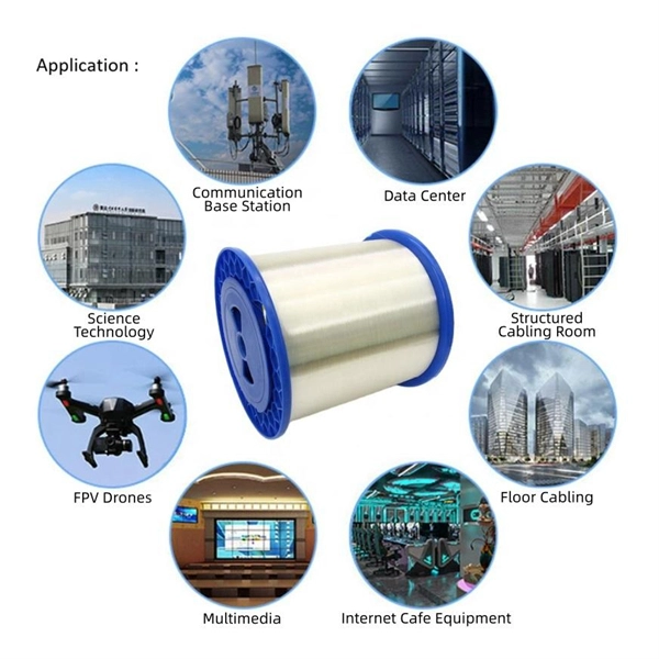
Arduino-Powered Data Transmission with Fiber Optics Welcome to our video tutorial on optical communication with Arduino, designed to be easy to follow, whether you're new to Arduino or have some experience. The fiber optical link provides long distance, fast speed, and low latency network connections. It can be deployed both outdoor and indoor for TCP/IP network applications such as IP surveillance, Wireless coverage, VoIP phone. Furthermore, it is known that the maximum distance of copper cat5e/cat6. In the spirit of self-reliance and technical mastery, we've crafted this detailed guide to empower you to take control of your own network by installing fiber optic cables yourself. This comprehensive guide equips you to be your own technician, exploring the intricacies of fiber optic technology. I'm going to use HFBR 1414 fiber optic transmitter module which is manufactured by Broadcom. It is a low-cost high-power transmitter that is designed for use in industrial power generation, power distribution, medical transportation and gaming applications. It represents a harmonious blend of science and practical application, bridging the gap between abstract concepts and tangible creations. In fiber optic circuit technology an optical fiber link is used for transferring digital or.
[PDF]
It enables uniform, shadow-free lighting by directing light along the same optical axis as the lens. When integrated into specialised lenses, the beam splitter divides the incoming light into two paths: one beam illuminates the object, while the other is used for image capture. Beamsplitters are fundamental components in optical engineering, serving to precisely divide a single input beam of light into two distinct output beams. This division allows for the simultaneous analysis or utilization of the light's properties along two separate paths. Additionally, beamsplitters can be used in reverse to combine two different beams into a single one. In practice, the reflective layer absorbs some light. It is a crucial part of many optical experimental and measurement systems. A cube beam splitter is, at its essence, an optical device that splits an incoming light beam into two sections. What are beamsplitters and how are they used in optics and photonics applications ? Beamsplitters are optical components that are used to. The beam splitter splits and then recombines infrared radiation, while the detector picks up the resulting signal. It's sensitive to both intensity and frequency. Together, they decide just how accurately an instrument captures those unique infrared “fingerprints” from different substances.
[PDF]
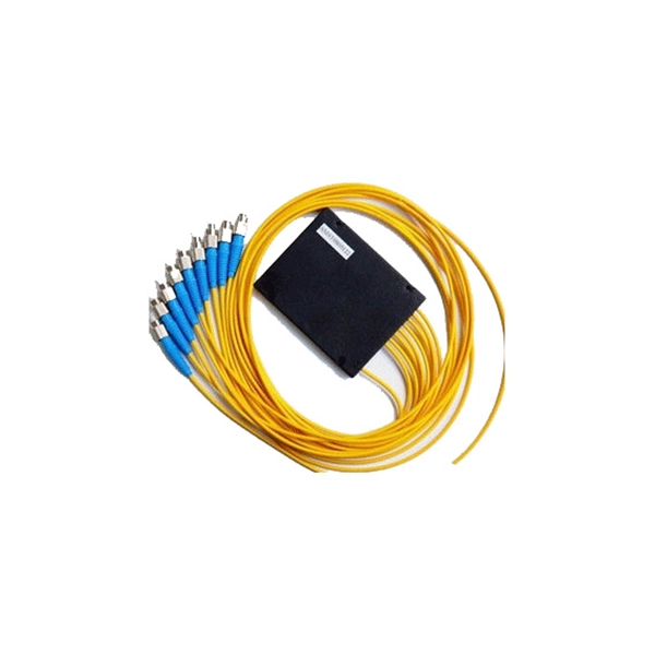
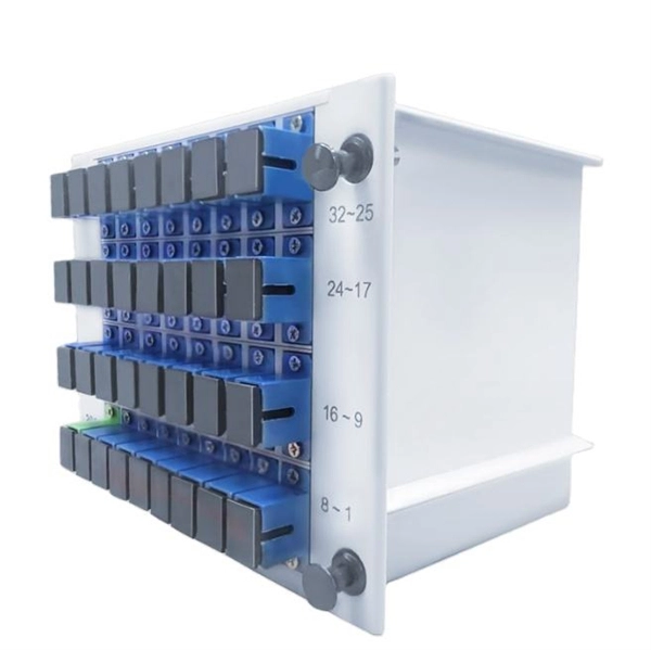
In fiber-optic communications, wavelength-division multiplexing (WDM) is a technology which multiplexes a number of optical carrier signals onto a single optical fiber by using different wavelengths (i.e., colors) of laser light. This technique enables bidirectional communications over a single strand of fiber (also called wavelength-division duplexing) as well as multiplication of capacity. The. SystemsA WDM system uses a at the to join the several signals together and a at the to split them apart. With the right type of fiber, it is possible to have a device that does both s. Originally, the term coarse wavelength-division multiplexing (CWDM) was fairly generic and described a number of different channel configurations. In general, the choice of channel spacings and frequency in these co.
[PDF]
This video shows 2D wave simulations of optical fibers and presents differences between single-mode and multi-mode light propagation. more Audio tracks for some languages were automatically generated. Learn more. This applet is called FIMOC (fiber-optic mode online calculator). With it you will be able to calculate and visualize the propagating modes of any step-index fiber of your choice. If you want to go directly to the software, scroll to the bottom, but if you are interested in where these modes come. Optical fiber sensors have attracted significant interest in the sensing field. This paper presents a C-shaped optical fiber sensor sensitivity enhancement through design. RP Fiber Power is a powerful software for simulation, design and optimization of fiber devices — in particular, fiber amplifiers and lasers as well as other types of waveguide lasers (and even many bulk lasers), but also fiber couplers, multi-core fibers, helical core fibers, tapered fibers and. In this proposed workflow, we couple Ansys Mechanical TM with Ansys Lumerical TM, creating an innovative workflow that can detect the position of a random mechanical strain along an optical fiber. In this proposed workflow, DFOS utilizes standard single mode optical fiber as a sensing element. 1Department of Mechanical and Aerospace Engineering, University of Texas at Arlington, 500 W.
[PDF]
Your eyes contain two types of light-sensing cells: rods and cones. Rods detect low-light vision and motion, while cones handle color vision and detail in bright light. Damage to either can lead to vision problems like night blindness or color blindness. Protecting your eyes with proper nutrition. Personnel Safety. Optical Touch Buttons. Self-contained Sensors. Each technology has unique strengths and weaknesses, so the requirements of the application itself will determine what technology should be used. This article is focused on photoelectric sensors and defines what they are, their adv ors are readily present. Quality Control: They can detect defects, ensure proper product placement, and verify the presence of components. Safety: They can be used to create safety barriers, preventing machinery from operating when a person or object is in a hazardous zone. In this section, we explore the geometric optics of the eye. Early thinkers had a wide array of theories regarding vision. Euclid and Ptolemy believed that the eyes emitted rays of light;. Understanding the eye involves examining how its individual parts contribute to the overall function. Vision begins as light enters the eye through the cornea, a transparent, dome-shaped outer.
[PDF]
Long-pass dichroic beam splitters are designed to transmit longer wavelengths of light and reflect shorter wavelengths, while short-pass dichroic beam splitters do the opposite. While this type of beam splitter is less common, it can be useful for fluorescent applications, such as. A beam splitter or beamsplitter is an optical device that splits a beam of light into a transmitted and a reflected beam. It is a crucial part of many optical experimental and measurement systems, such as interferometers, also finding widespread application in fibre optic telecommunications. In its. Beamsplitters are optical components used to split incident light at a designated ratio into two separate beams. Additionally, beamsplitters can be used in reverse to combine two different beams into a single one. Newport offers a wide variety of Beamsplitters in various shapes. a laser beam) into two (or sometimes more) beams, which may or may not have the same optical power (radiant flux). These plates are typically made of high-quality glass coated with a thin, anti-reflective film. The coating helps to minimize issues with annoying back reflections, such.
[PDF]
The AOI impacts the amount of light being reflected and transmitted. For example, most plate beam splitters have an AOI of 45 degrees, which may limit those who need more flexibility. A beam splitter or beamsplitter is an optical device that splits a beam of light into a transmitted and a reflected beam. It is a crucial part of many optical experimental and measurement systems, such as interferometers, also finding widespread application in fibre optic telecommunications. a laser beam) into two (or sometimes more) beams, which may or may not have the same optical power (radiant flux). Their precision and versatility make them indispensable in a variety of scientific, industrial, and technological applications. Beamsplitters are often classified according to their construction: cube or plate. Beamsplitters are fundamental components in optical engineering, serving to precisely divide a single input beam of light into two distinct output beams. This division allows for the simultaneous analysis or utilization of the light's properties along two separate paths. The device is purely. The beam splitter splits and then recombines infrared radiation, while the detector picks up the resulting signal. It's sensitive to both intensity and frequency. Together, they decide just how accurately an instrument captures those unique infrared “fingerprints” from different substances.
[PDF]
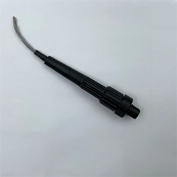
The worker must then connect one end of the fiber optic cable to a light source. Then, once they have done this they will turn on the light source and press the button on the. When it comes to testing fiber optic cables, a Visual Fault Locator (VFL) is an essential tool in your toolkit. A VFL is used to detect faults, breaks, or bends in fiber optic cables by emitting a bright red light that is visible even through the fiber's jacket. It's a cost-effective and. How to use fiber optic red light pen? It can be seen from the above that the red light pen has many uses, but its most common use is to detect the connectivity of the optical fiber and locate the fault point of the optical fiber. more How to use a VFL to identify a fiber optic cable from end to end. Viavi VFL:https://amzn. to/3L7cL6RTools I use:3 Hole Strippershttps://amzn. Within the pen, a small but powerful laser sends out an intense red light. Here is how the pen helps detect errors. If the fiber optic cable is appropriately intact and. The RPEN-210 is a necessity tool that should not be missing from any fiber plant manager or fiber optic installing technician. The Visual Fault Locator (VFL) Pen has a visible red light source centered on 650nm. Tool sends visible light over a fiber strand with a 10mW power, good enough to reach.
[PDF]
Check the electrical load and ensure that the sensors do not exceed the 10 Amp maximum. Check each wire for damage that may lead to a short. Check the following: Check if all cable connections are tightened with a torque moment of 14Nm (17Nm for the M10 model). Check if the surface area. Channel has NO voltage and there is an active fault. Check for tripped or missing circuit breaker Sticky fault on the channel. Sticky Fault - an indicator that a fault has occurred that will stay until the indicator has been cleared manually. Channel has NO. Each powernet distribution box (PNDB) on the vehicle provides up to 4 low amperage circuits (30 amp and less), and up to three high amperage circuits through midi fuses. The fuses are located behind a cover on the face of the PNDB. On vehicles equipped with a cab load disconnect switch (CLDS), the. I have the following issues, green light on shunt all red lights on distributor, no SOC on screen. Everything else is working great. In troubleshooting I removed all the fuses from the distributor just to see if the fuse lights would not illuminate red and get green power. Any. Show the control box indicator lights. Show the accessory response (or lack of response). For LED Light Kit issues, also provide a photo of the LED Y-cable (to confirm which version you have). Videos and photos are required to file warranty claims with the manufacturer.
[PDF]
An optical attenuator is a passive device used to reduce the power level of an optical signal, either in free space or in an optical fiber. There are various types of them from the fixed ones, step-wise variable, and continuously variable. Signals may be attenuated. Fiber loss, also called fiber optic attenuation or attenuation loss, refers to the loss of signal between input and output. Losses can be introduced by various means such as intrinsic material absorption, scattering, bending, connector loss and more. It provides an expert-curated supplier directory, buyer-focused technical background information, and structured selection criteria to support professional procurement decisions. What is a Fiber-optic Attenuator?. To determine the power budget and power margin needed for fiber-optic connections, you need to understand how signal loss, attenuation, and dispersion affect transmission. Understanding the causes of signal loss and implementing mitigation strategies is essential for maintaining network efficiency. From infrastructure planners to telecom engineers. However, there is light leakage when PMMA optical fibers transmit concentrated sunlight, resulting in a transmission efficiency lower than the theoretical value. This research aims to quantitatively study the light leakage effect of PMMA optical fibers. Concentrated sunlight was used as the.
[PDF]
This guide explains how to make 90° bends, vertical bends, tees, and offsets in wire mesh cable trays safely and professionally. Horizontal 90° Bend (Flat Bend) 2. Tee (T-Junction) Bend 4. Since the jaws of the bolt cutter drags a layer of zinc across the cut end and forms a protective layer. When a wire cable tray is cut, the fact that a. Wire mesh cable trays are widely used because of their flexibility and easy on-site modification. Unlike perforated trays, bends can be created directly at site without expensive fittings. Includes a full demonstration on how bend steel cable tray using a crimping to. more. ns and Cross Joints. These arrangements can be created by using our standard cable tray sections and removing specific pieces as directed using the Cutter tool (WR-TRAYCTR65), and then bending and securing the tray pieces together using Couplers (WR-CPLKK34), Corner Strength Bars (WR-CNRSBAR-EZ). Before bending a cable tray, it is crucial to prepare it properly. This involves a few essential steps to ensure a successful bending process. The first step in preparing the. This manual is designed to guide workers through the detailed production process of ladder cable trays, including the manufacture of horizontal elbows, tees, crosses, reducing bends, and vertical bends, with emphasis on precision, safety, and quality control. What's Involved in Producing Ladder.
[PDF]
The production of cable tray elbows requires the following steps:1. Determine the angle and required radius size of t. Here is the simple solution Create two type : 90 elblow and 45 elbow In the real world, to make a 45 elbow, we need two segments, to make a 90 elbow, we need three segments I've also tried to use some geometry forms in revit but no hope. Choose suitable metal materials based on the. To cut a cable tray for a 45-degree bend, you need to make two 22. 5∘ cuts on two separate pieces of cable tray. Each cut should be 22. 5∘ from a perpendicular line drawn across the tray's width. The second piece's cut must be in the opposite direction to the first, allowing them to join and form the. The bends, tees, crosses, risers and reducers of wire mesh cable tray can be easily and quickly made live at the project by using a bolt cutter. Since the jaws of the bolt cutter drags a layer of zinc across the cut end and forms a protective layer. So I can then use the formula on different cable tray sizes and to different angles. 3 (2" CABLE FILL) F = POLYESTER 06 = 6" 45 = 45 DEG. VO = VERTICAL RADIUS THIS DRAWING AND/OR THE TECHNICAL INFORMATION CONTAINED HEREON IS THE PROPERTY OF EATON CORPORATION ("EATON"), AND IS ISSUED IN CONFIDENCE FOR EATON ENGINEERING PURPOSES ONLY AND MAY NOT BE REPRODUCED OR USED FOR ANY PURPOSE.
[PDF]
The Light Cube can be dyed using any color cube. Upon merging, it adopts the color of the cube used. Each dye attempt increases a dye counter, tracking how many times it's been recolored. 💡 Note: These items transform when fused with a Light Cube. The glow effect varies based on dye count. or if you want to see a video, then here: https://www. Each dye. This is a light cube DIY kit that you need to weld and assemble by yourself. The bottom plate comprises a circuit board and component parts. The 512 LED lights make up a stereo space. A variety of cool model showing a three-dimensional effect. It's better to watch in the night. Installation Manual:. 8x8x8 LED Cube Kit DIY Electronic Kit Soldering Project Kit, User Needs to Solder The LED, and The Displayed Content Can Be Modified. (GZT-64) Shop products from small. The dot matrix component features 25 RGB color light clusters, arranged in a 5x5 grid. Each individual light bead offers 16000K color variations, all of which can be controlled via an APP. When these 25 light beads come together, they provide an infinite array of color possibilities. It can craft some pretty decent weapons and it can make my favorite structure, Lantern! I hope you enjoy! :D. A light source has been placed inside to create interesting shadows. The pieces in this project can connect to each other without using any glue (however using glue.
[PDF]