In this video, we take you through the step-by-step installation of Optical Distribution Frames (ODF) and Optical Fiber Patch Panels—key components in setting up a robust fiber optic network. At Eman Communications, we specialize in delivering high-quality installations that ensure opt. more In. Fiber optic patch panels are mostly mounted in 19 inch relay racks, but they can also be mounted on freestanding rails, in cabinets and also on walls. The fiber optical patch panel is convenient for people to easily access the optical fiber cable in the panel. Keeping this page as a placeholder for now. Have any questions? Talk with us directly using LiveChat. An ODF is a centralized platform designed for terminating, cross-connecting, and managing optical fibers. It ensures fiber management is structured, minimizes signal loss, and provides accessibility for maintenance and future expansion. ODF Rack/Cabinet: Physical frame housing all terminations and. To connect fiber optic cables to a patch panel, users must follow a specific procedure that ensures proper connectivity and signal transmission. Here is a step-by-step guide on how to connect fiber optic cables to a patch panel. Step 1: Gather the Tools and Equipment The first step in connecting.
[PDF]
In this article, you will learn the step-by-step process of testing your solar panels using a multimeter. We will cover the essential tools you need, the specific measurements to take, and how to interpret the results. By the end of this guide, you will be equipped with the knowledge to diagnose. Solar panels are usually tested under standard conditions using a light source that mimics the light from the sun on a clear day. You can use the following method if you want to test your solar panel under standard conditions. Testing solar panels is easy with a multimeter! To test the current. Your multimeter is your best friend when testing solar panels. You can use it to check: Here's how: Multimeter — I recommend getting one that is auto-ranging. Also, a simple voltmeter won't work here. You need a multimeter that can measure both volts and amps. Locate the open circuit voltage. Learning to test a solar panel with a multimeter is an investment in your knowledge and ability to manage your own solar energy system or provide valuable services in the growing solar industry. Measure Voc (open circuit voltage) — if it reads 0V, the panel or wiring is dead. If it reads 60–80 % of rated, a bypass diode has failed. Perfect for DIY solar builders, RV owners, o. more Audio tracks for some languages.
[PDF]
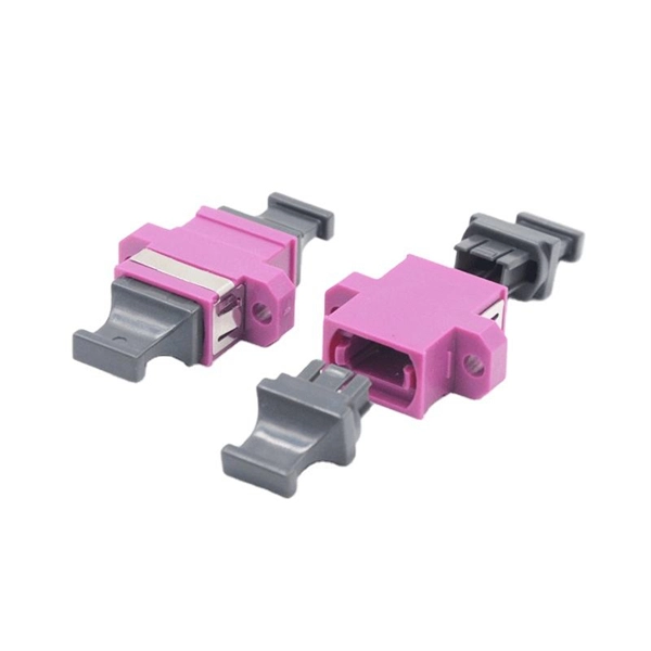
Mouser offers inventory, pricing, & datasheets for Duplex Fiber Optic Connectors. Check each product page for other buying options. QIANRENON LC Fiber Panel Mount Adapter LC Fiber Optic Connector Socket LC Fiber Coupler Module. XLR Panel/D-Panel Mount, for Fibre Optic Network LAN Integrated Cabling Need help?. Pricing (USD) Filter the results in the table by unit price based on your quantity. A tariff of 10% may be applied if shipping to the United States. A. Fiber Optic Connectors are the ends used to terminate optical fiber cable. The connector styles are DNP, ESCON, FC, FDDI, FSD, FSMA, LC, MPO, MT-RJ, MU, SC, SCRJ, SCRJ and Power Jack, SMA, ST, TNC, and VF-45. The mode options are multimode (OM1, OM2, OM3, OM4), POF, and Singlemode (OM1). These. High quality faceplates, RJ45 plugs, and copper, audio, video, and fiber optic modules from Molex, Leviton, CommScope, SignaMax, and more. COM supplies different types of fiber optic wall plates outlets, including angled ports fiber optic wall plate outlets. The angled opening provides a low profile and strain relief and allow fiber connectors and jumpers. Corning wall-plate outlet (WLL) is a highly configurable outlet product, available in both single- and double-gang configurations. It is designed for use within fiber-to-the-desk (FTTD) applications but may also be used to connect telephones and other peripherals to a network. A variety of fiber and.
[PDF]
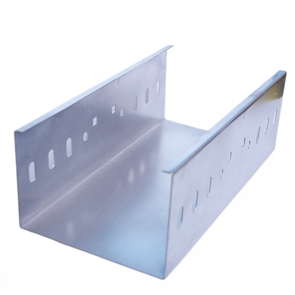
The main parts are the Miniature Circuit Breaker (MCB), Residual Current Device (RCD), busbars, and the main switch. Safe habits and checking the box often help stop electrical accidents. Learn about the main parts in a distribution box. These are MCBs, RCDs, busbars, and the main. A distribution box is a key part of electrical systems in buildings. Inside, you'll find parts like circuit breakers and fuses that protect the system from problems like overloads and short circuits. Today, electrical systems are essential for homes and industries. But what exactly is a power distribution box, and why is it so essential in our daily lives? The DB panel board controls the flow of electricity. Electrical systems power our homes, offices, and industrial facilities, but behind every reliable electrical setup lies a crucial component that often goes unnoticed: the distribution box. If you know. The internal structure of the distribution box is designed to safely distribute power from the main power source to multiple branch circuits. It provides convenience for protection, control and maintenance.
[PDF]
This diagram highlights media converters, switches, and cable types. Also thanks to Init7 (for the great service), r/FiberOptics and FS for providing me with what I needed to get this setup going. If you find this article useful and you are considering Init7 as your provider you can use my referral code “20700408098” to get CHF 111. - off hardware and also support me. Keeping this page as a placeholder for now. Have any questions? Talk with us directly using LiveChat. A fiber optics network diagram illustrates how high-speed data travels from an internet service provider to end users. By using light signals, fiber optics provide faster speeds and better reliability than. MS Visio has long been the default choice for drafting fiber network diagrams, and with the right stencil libraries it can be used to draw everything from backbone routes to detailed patch panel layouts. When fiber techs look for visio fiber stencils, they are usually solving a very practical. Be among the first to receive important product updates, insights and news. Fiber optic cable is used for everything from demarcation point wiring to network signal distribution to video signal extension. Often, fiber enters the structure to a centralized rack or data room where it is connected to a modem. The modem connects to a network switch which connects each remote.
[PDF]
Insert a compatible SFP transceiver into the converter's port, making sure it matches the network's media type and speed. Then, connect one end of the fiber cable to the transceiver and the other to the appropriate port on a switch, router, or another media converter. Fiber media converters translate copper's electrical signals into fiber's optical signals, and back again. This allows networks to extend beyond the 100 m copper limit while gaining higher bandwidth and resistance to electromagnetic interference. In the illustrated setup, each LAN links to a. A fiber media converter is a networking device that allows you to convert a signal from one medium to another. This allows you to connect devices that use different types of cabling, such as a computer. While fiber optic ports are becoming increasingly common on networked electronics, the majority of connected devices still rely on RJ45 twisted pair connections. To help bridge the copper-fiber divide, media converters and transceiver modules (also known as SFPs or mini-GBICs) are often required. Use Fiber Media Converter in Your Network Media converters today are widely deployed in all. It is a device used to convert fiber optic cables to Ethernet cables to provide better connectivity. It is necessary to convert fiber optic signals to Ethernet signals because many network devices can only communicate with Ethernet signals. Fiber optic cables are known for the unmatched speed.
[PDF]
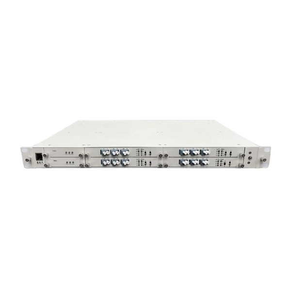
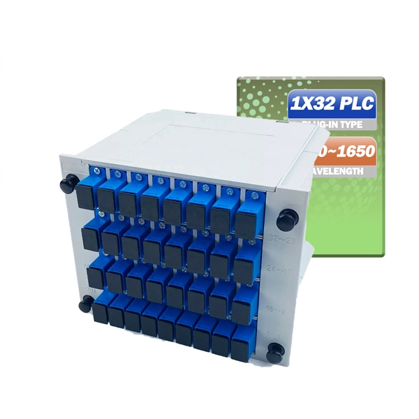
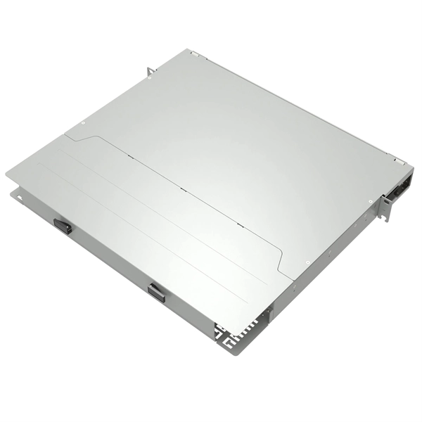
The panel can be pre-loaded completely with the required adapters or pre-loaded with pigtails and splice accessories. The tray is locked by 2 plastic latches and lowers to a 45 degree angle when fully extended. Installation and labeling are simple and easy. FS offers FHD® FAPs and FHU® 1U fibre patch panel with LC, SC, MTP®/MPO connectors in singlemode/multimode fibre to deploy medium for high-density fibre optic network applications. A patch panel or fibre distribution panel is a metal frame with pre- punched holes equally spaced horizontally along the front face. Unpopulated patch panels can be configured with bulkhead. A carefully selected range of fibre optic termination and patch panels from leading brands including Panduit, Canford and Speedway. A handy tool to for quickly finding a populated fibre connection panel that meets your requirements. Rack mounted fibre patch panels create a convenient, professional and easy access way to organise your fibre cables into a cabinet. Latest Optical Fibre Patch Panels for fibre installations.
[PDF]
Square D by Schneider Electric offers a unique replacement kit designed to adapt to all brands, different use case scenarios and load type devices such as Load Centers and CSEDs. This kit consists of tw.
[PDF]
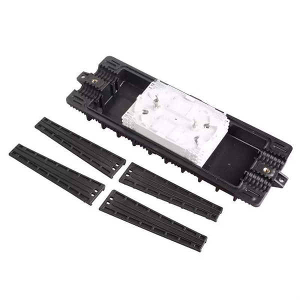
Instead of fusing one fiber at a time, mass fusion splicing can fuse up to all 12 fibers in one ribbon at once. Many of today's cables with high fiber count involve subunits of 12 fibers each that can be quickly ribbonized. Fiber optic joints or terminations are made two ways: 1) splices which create a permanent joint between the two fibers or 2) connectors that mate two fibers to create a temporary joint and/or connect the fiber to a piece of network gear. Either joining method must have three primary characteristics. Fiber optic splicing is the process of seamlessly joining two single Splicing has a lower optical loss and back-reflection than other terminations, making it the ideal choice for maintaining signal integrity and reliability in fiber optic networks. There are numerous use cases for fiber optic splicing. Through splicing, fiber optic technicians can extend the length of the fiber to make it long enough for use in a required cable run. As. To begin, the standard definition of splicing in optical fiber is joining two fiber optic cables together. The other, more common, method of joining fibers is called termination or connectorization. Splicing is most commonly used in the field but has application in cable assembly houses.
[PDF]
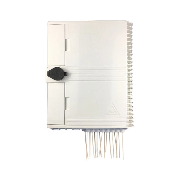
Fiber distribution box, also known as fiber optic distribution frame, is an essential component in fiber optic communication networks. It plays an important role in organizing, managing, and protecting fiber optic cables, ensuring reliable and efficient network operations. With features like IP68 waterproof ratings, fast connectors, and hardened adapters, distribution boxes enhance data transmission by offering proper termination points and environmental protection. It provides a secure space where incoming fiber optic cables from the provider's network are. A fiber distribution cabinet is a key component in modern fiber optic networks, designed to manage, protect, and distribute optical fibers efficiently. It serves as a central point where fiber cables are terminated, spliced, and organized for further connection to end users. The distribution box provides.
[PDF]
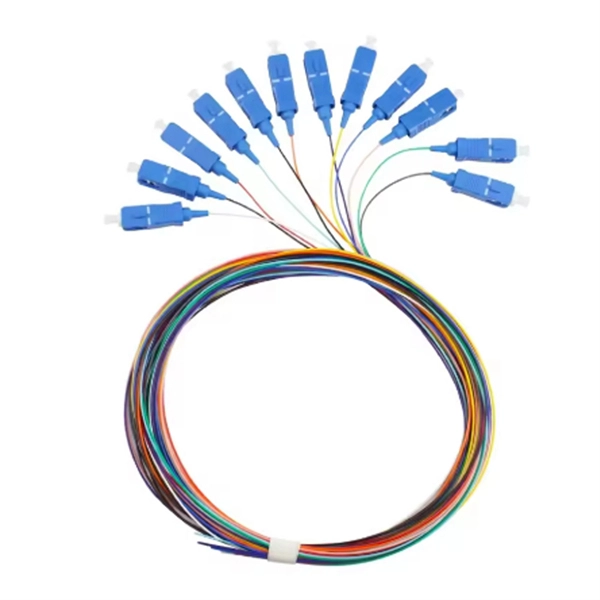
Summary : Fiber optic color codes are crucial for efficient, accurate, and reliable network installations. This guide explains how standardized fiber strands, cable jackets, connectors, and MPO systems simplify identification, prevent mismatches, and maintain signal. Tired of sorting poorly colored fibers? WolonFiber's 12-Color Fiber Optic Pigtail Packs are manufactured strictly to the TIA-598-C standard with vibrant, easy-to-identify colors. Perfect for fast, error-free termination in your ODF or splice closures. Following industry. You'll learn how to identify single-mode vs. multimode at a glance, trace individual strands in a 144-fiber bundle, and avoid the critical error of mixing connector types. In fiber optics, color isn't for decoration; it's a critical safety and efficiency tool. The TIA-598 standard (specifically. While labeling text offers specific details, color-coding makes it easy to identify cable uses or zones. In accordance with TIA-598-D standards fiber optic cables are based on the standard colors for jackets in single-mode: yellow, aqua/orange for multimode. 3 Create your own standards using colored.
[PDF]

This document provides a comprehensive technical overview of the Ring Main Unit (RMU), serving as a reference for power system design, selection, and maintenance. Ring Main Units (RMU s) and Medium Voltage (MV) Switchgear are crucial in MV power distribution. Globally, they each hold about half the market share. MV switchgear handles primary distribution for large industrial facilities and grid infrastructure. RMUs, however, shine in secondary distribution. RMUs are commonly used in secondary distribution systems, particularly in urban areas, industrial complexes, and commercial. Scope of Application: The Ring Main Unit (RMU) is a compact switchgear device used in medium-voltage power distribution systems (typically 10kV–35kV). Some of the key features of the RMU includes SF6 gas insulation, compact and modular construction, integral protection system, fully extendable options. SFA-RM units are designed for supplying reliable energy, protecting electrical equipment in secondary distribution networks up to 17. Their compact design makes them suitable for various network applications such. Loading. Company Introduction:The New Concept Electric Inc. (NCE) was founded in October 2001, with a registered capital of 57 million Yuan. The company now covers an area of 77, 601 square meters (116 acres), and has a building area of 80, 451 square meters.
[PDF]
As shown in the figure below, the main cable consists of three conductor wires extending from the top of the motor flat lead extension to the wellhead banded to the production tubing. The ESP cable carries current (amperage) from the motor controller at the surface down to the motor. CAVALCADE™ ESP power cable meets the high-quality standards required for any oil and gas industry specification–even the most challenging unconventional applications–to deliver the electrical requirements of your ESP and to extend system run life. Get cable built with solid copper conductors. Typically, it is banded or clamped to the production tubing from below the wellhead to the ESP unit because it is not designed to support its own weight. It is a specially constructed three-phase power. Levare is one of few artificial lift equipment providers manufacturing the complete ESP system including power cable. The total facilities capacity is approximately 10,000 kilometers (over 6,200 miles) of power and motor lead extension (MLE) cables annually. It is a specially constructed three-phase power cable designed. When performing well interventions, the choice of a suitable cable is critical to ensure well control is maintained while deploying wireline through pressure control equipment (PCE). Depending on the well conditions, many considerations should be taken into account for choosing the best cable.
[PDF]
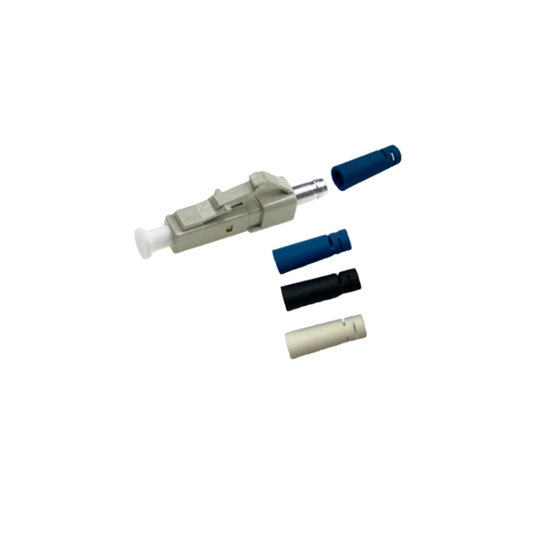
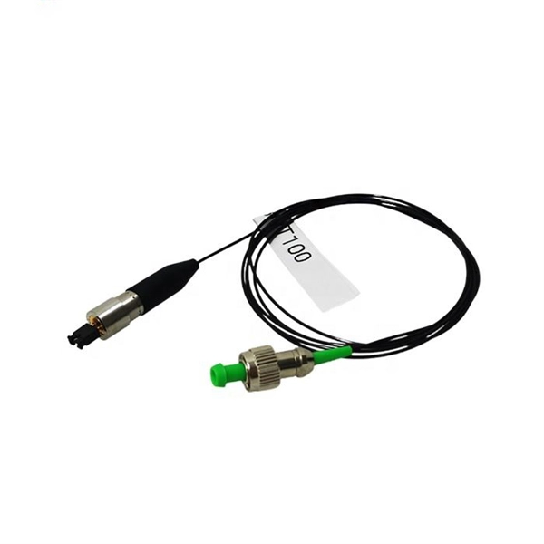
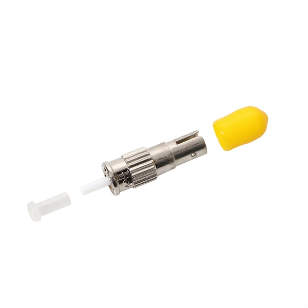
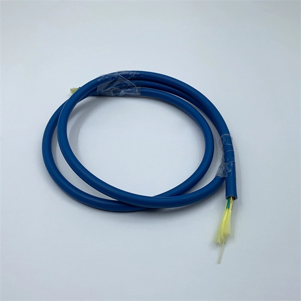
The most commonly used patch cable connectors today include FC, ST, SC, LC, MTRJ, and MPO connector types, as well as newer very small-form-factor (VSFF) CS, SN, and MDC connectors used in high-density, high-speed duplex data center environments. This guide will help you quickly understand the main types of fiber patch cords and how to choose the right solution for your project – and how ZION can support you with stable quality, flexible customization and global supply. What Is a Fiber Optic Patch Cord? A fiber optic patch cord (fiber. An optical fiber patch Cable is a jumper wire used to connect from equipment to an optical fiber cabling link, and it is usually used for the connection between an optical transceiver and a terminal box. It is widely applied in fields such as optical fiber communication systems, optical fiber. Fiber optic patch cords, also known as fiber optic patch cables or fiber jumpers, are indispensable components in modern optical networks. They act as the critical link for interconnecting devices like optical switches, servers, and distribution frames. Behind its slender appearance lies the fusion of core types, connector types, and polish levels, each chosen for a specific application. It is composed of fiber optic cable and fiber connector that fixed at both ends of optical cable, has been widely used in various fields such as fiber optic.
[PDF]
At the heart of every optical transceiver lie three essential components, often called the “Three Pillars” of optical communication: Laser — generates light. Modulator — encodes data onto the light. Photodiode — decodes light signals back into electrical form. As an essential component of optical fiber communication, optical modules are optoelectronic devices that facilitate the conversion between optical and electrical signals during the transmission process. Operating at the physical layer of the OSI model, optical modules are core devices in optical. An optical module usually consists of an optical transmitting device (TOSA, including a laser), an optical receiving device (ROSA, including a photodetector), functional circuits,main control circuit board (PCBA), housing and optical (electrical) interface and other components. Together, lasers, modulators, and. That is, metal medium communication represented by coaxial cables and network cables is gradually being replaced by optical fiber media. Composition of Optical Modules The optical module, known as Optical Transceiver in. This comprehensive guide breaks down the internal structure, core components (TOSA, ROSA, lasers), and operational mechanisms of SFP optical modules, enriched with technical insights and real-world applications. These modules typically consist of a transmitter, which converts electrical signals into a light signal, and a receiver, which converts the received signal back.
[PDF]