ShowMeCables offers a wide selection of LMR-600® thick low loss cables for long-distance runs. These LMR-600 cables are designed with flexibility, low loss and RF shielding with options such as ultra-flex, weatherproof and fire retardant rating for safe indoor, outdoor, or direct. TC-240-FM-X 3190-2891 <1. N Male Straight Plug 3. 35:1 (6) Hex/Knurl Solder Crimp A/G 1. Since 1975 delivering the world the best copper and copper alloy products to build a more connected, clean and efficient planet. is a Peruvian manufacturer that specializes in the design and production of electrical cables and conductors made from copper and aluminum for low and medium voltage applications. These. Check each product page for other buying options. Alligator Clips Electrical with Wires UL1015/18AWG, 6 Colors Jumper Test Leads Set, 1. Clips Soldered with Wires- EDGELEC Need help?. Our wire and cables have been helping real, hardworking pros on the job for more than 45 years. Their success is our success. Direct Wire is widely known as the market leader for highly durable and versatile cables and assemblies manufactured to stringent U. and international standards.
[PDF]
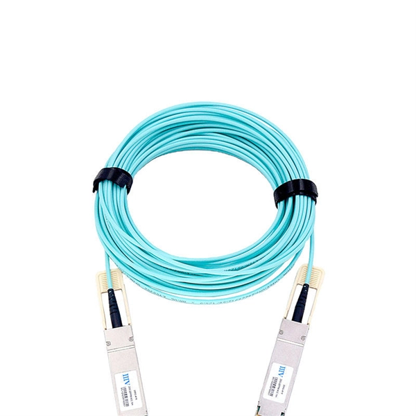
This article provides an in-depth exploration of OSFP copper cable technologies, including DAC, ACC, and AEC, with a focus on 400GB NDR splitter cable applications. Whether the signal is propagated by copper wire, optical fiber, Wi-Fi, or just yelling at the kids down the street, the signal is never as strong at the destination as it is at the source. In the case of physical voice communication, the kids will understand you if they are close-by. If they are. Insertion loss and attenuation are similar concepts, but one is assigned to a single component (insertion loss) whereas the other is assigned to generalized performance (attenuation). Both terms refer to a measurement comparing the signal strength received against a transmitted signal. Standard. Channel Master TV splitters are designed to equally divide the signals on the input port of the splitter to each of the output ports of the splitter. This. Insertion loss is the amount of energy that a signal loses as it travels along a cable link. It is a natural phenomenon that occurs for any type of transmission—whether it's electricity or data. This reduction of signal, also called attenuation, is directly related to the length of a cable—the. In fiber-optic networks like FTTx and PON, PLC splitters are key components for distributing optical signals to multiple users. However, each splitter has complex parameters, including insertion loss, return loss, polarization-dependent loss, and uniformity.
[PDF]
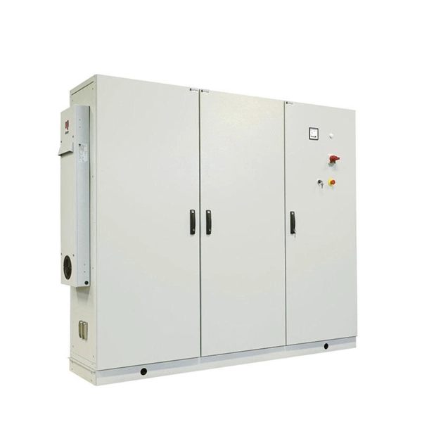
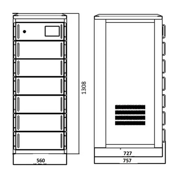
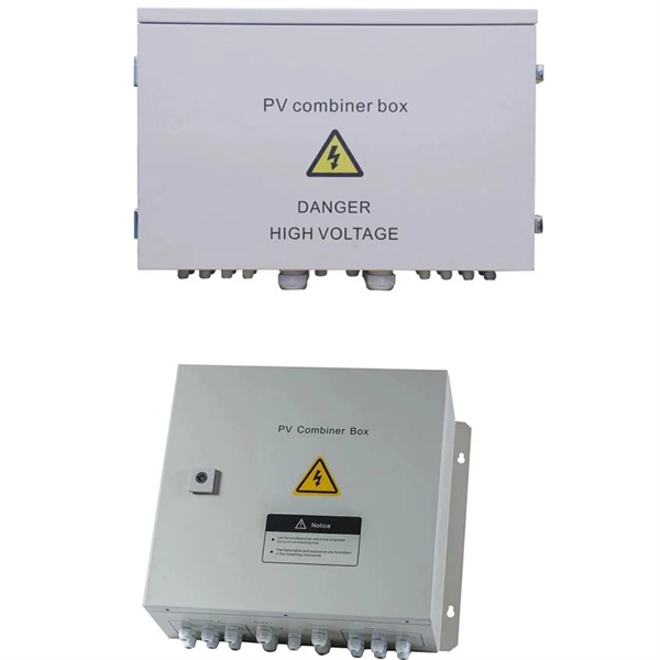
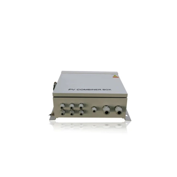
With vast rural areas lacking grid access, battery energy storage systems (BESS) provide reliable electricity for communities and industries. Imagine a solar farm in the Andes storing excess dayt Bolivia's growing energy demands and remote terrain make the BESS outdoor power . As Bolivia's fastest-growing urban center, Santa Cruz faces unique energy demands that require robust outdoor power solutions. Whether you're a homeowner seeking backup options or a business owner. Imagine a solar farm in the Andes storing excess dayt. The world"s largest PV-diesel hybrid power plant system with battery storage was commissioned in December 2014, in the Bolivian province of Pando. SMA is not only supplying photovoltaic inverters Bolivia"s growing industrial and commercial sectors demand stable power solutions. Whether you're a homeowner seeking backup options or a business owner. Aug 13, 2025 · How We Selected and Tested To pick the best solar generators, we tested some of these power stations for charging capacity, Aug 29, 2025 · Bolivia"s solar development has reached a new height of a 3MW ground solar project, the largest solar plant in the private sector within the. If you are looking for Electrical Panel, we have LT Distribution Panel, Load Management Panel, Outdoor Power Panel, Marshalling Panel, and Power Control Panel In Bolivia. So get in touch with us for your Panel need. An electrical cable is a current-carrying assembly of wires that runs side by side.
[PDF]
The devices has a wide pass band, low insertion loss, high channel isolation and excellent environmental stability. Channel numbers can be as high as 40 (16) for 100 (200)GHZ systems in C band or in L band. They can be used in DWDM systems to perform a multiplexing or. Fiberdyne Labs offers Dense Wavelength Division Multiplexer (DWDM) Modules in a wide variety of formats. While Fiberdyne offers some models as "standard," we will also produce customized DWDM modules. Customization can include the number and selection of DWDM channels. Channel. AFL's DWDM LGX modules provide scalable wavelength management for new deployments and network upgrades, providing increased bandwidth over a single common fiber. Based on thin film filter technology, the device is less than one-third the size of traditional cascaded DWDMs of similar channel count. Modules can be installed in standard LGX chassis and are available with LC bulkheads in select. All parameters are for device without connectors 2. Special specifications can be customized according to customer requirements DWDM mux demux and optical modules for high-capacity fiber networks. 40/80-channel options, rack mount or LGX type, low insertion loss, high stability. Ideal for telecom.
[PDF]
Integrated optical switching delay line (OSDL) chip, which is composed of optical switches cascaded with optical waveguides of different lengths, has the merits of ultra-wide delay bandwidth, very high delay accu.
[PDF]
A fiber optic adapter (or fiber coupler) is a passive component used to join and align two optical connectors. It plays a key role in maintaining core-to-core alignment, allowing optical signals to pass through with minimal insertion loss and stable performance. They enable seamless and reliable optical signal transmission between different fiber optic cables, connectors, or devices. In this tutorial. Fiber optic adapters play a critical role in ensuring stable and low-loss fiber connections. This guide covers adapter types, selection criteria, cleaning tips, FAQs, and B2B customization options to help businesses build reliable and scalable fiber networks. Using the wrong type or neglecting cleaning can lead to signal loss and unstable connections. These small yet essential components ensure efficient data transmission, reduce signal loss, and maintain system integrity (1). In this article, we'll explore. Explore the role, types, and applications of fiber optic couplers in telecommunications and data networks in our in-depth article. They serve an essential role in managing the flow of light.
[PDF]
Attenuation is the natural loss of signal power over distance. This is inherent in all fiber types and happens even under ideal conditions. Factors such as wavelength and fiber quality influence attenuation. At shorter wavelengths like 850nm, attenuation is higher, especially in. To be able to judge whether a fiber optic cable plant is good, one does a insertion loss test with a light source and power meter and compares that to an estimate of what is a reasonable loss for that cable plant. The estimate, called a "loss budget" is calculated using typical component losses for. A significant signal loss in the optical fiber can cause unreliable transmission. How can we know the value of losses on the fiber link? Read on, this post will teach you how to calculate the losses in optical fiber and judge the fiber link performance. What is optical fiber loss? Fiber loss can be. At TREND Networks, we are frequently asked how much loss is allowed when conducting testing on fiber optic cabling. So how do you determine acceptable loss? When testing fiber optic cabling, determining acceptable loss is. Understanding fiber loss is vital in maintaining a reliable, efficient network. While some loss is expected, excessive or unexpected loss can lead to poor performance, network. Optical fiber loss is a term for signal loss affecting transmission reliability. So how is the fiber attenuation calculation? 1, ODN full attenuation accounting: According to the worst value.
[PDF]
ITU & IEC allow 0. 75 dB loss per mated pair. Splitter loss values are "Typical" and include a connector in and out. These values are approximate and should not be exceeded by more than 1-1. 5 dB, which could indicate dirty connectors, bad splices . ITU & IEC allow 0. Passive split links usually lose the most dB at the splitter, so we keep the optical budget and the installed route separate. Measured in feet for imperial mode. Drop length Adds. Calculate split loss, excess loss, and terminations for any ratio quickly today. See power budget impact instantly, then download a CSV or PDF summary. Use 2×N when two inputs feed the same distribution stage. Common values: 2, 4, 8, 16, 32, 64. Abridged Optics — Beam Splitter Calculatorv1. 0Fresnel calculations assume a single uncoated interface. Real beam splitters use multi-layer coatings that modify R/T beyond Fresnel predictions. Understanding the types of splitters, their impact on network performance, and how to measure their losses ensures high-quality network operation and facilitates optimal splitter selection based on. This value should be determined by the system designer. 3 recommends a maximum value of 0. Total Splice Loss (The maximum splice loss permitted for installation. Components, such as fiber cables, splitters, and switches, introduce attenuation.
[PDF]
This document describes how to use and program the Photonic Application Suite, Insertion Loss Engine. Insertion loss is measured by comparing signal power (or sound level) before and after it passes through a component or system, then expressing the difference in decibels (dB). The core process is the same across fiber optics, RF electronics, and acoustics: establish a baseline reference without. This tutorial aims to help RF engineers understand how to test and measure various RF specifications of RF power amplifiers, RF LNAs (Low-Noise Amplifiers), and RF transceivers using RF test and measurement equipment like spectrum analyzers, signal generators, and sweep oscillators. Gain is the. Coaxial cables are essential components in transmitting radio frequency (RF) signals, but they inherently attenuate these signals, a phenomenon known as cable loss or insertion loss. Yes, I would like to receive educational or promotional emails from Keysight. By clicking the button, you. Insertion loss is a critical parameter in RF engineering that refers to the loss of signal power that occurs when a component or device is inserted into a transmission line or circuit. The insertion loss measurement quantifies the effect of the resistance the cabling link offers to the transmission of the electrical signals. Insertion loss characteristics of a.
[PDF]
For singlemode fiber, the loss is about 0. 5 dB per km for 1310 nm sources, 0. 5 dB/km at either wavelength for outside plant max per EIA/TIA 568)This roughly translates into a loss of 0. 1. To be able to judge whether a fiber optic cable plant is good, one does a insertion loss test with a light source and power meter and compares that to an estimate of what is a reasonable loss for that cable plant. The estimate, called a "loss budget" is calculated using typical component losses for. Manufacturers provide a fiber loss factor in dB per kilometer. Total fiber loss is calculated by multiplying the distance by the loss factor, considering the actual cable length. 25 dB/km (@1550nm) and 0. Understanding where those losses come from, and how to calculate them, is essential for designing a link that actually works. The decibel is. A loss budget in fibre optics is a detailed accounting of every potential source of signal attenuation (loss) in a fibre optic link. By accurately calculating and managing loss budgets, engineers and technicians can guarantee that optical signals reach their destination with enough power to be. After measuring the loss of a fiber link, you now have to determine if that fiber link loss is acceptable or not. Here are the details and instructions about each field and how they contribute to the calculation: 1. Attenuation Coefficient (dB/km): This value represents the inherent signal loss per kilometer of.
[PDF]
Acceptable dB loss for fiber depends on the component you're measuring: a single mated connector pair should lose no more than 0. 75 dB, a fusion splice should stay under 0. 3 dB, and fiber cable itself loses between 0. To be able to judge whether a fiber optic cable plant is good, one does a insertion loss test with a light source and power meter and compares that to an estimate of what is a reasonable loss for that cable plant. The estimate, called a "loss budget" is calculated using typical component losses for. Q: What is fiber optic loss? A: Fiber optic loss refers to the reduction in signal strength as it travels through the fiber optic cable. This can be due to various factors, including attenuation, connectors, and splices. Q: How is fiber optic loss measured? A: Fiber optic loss is typically measured. Fiber loss can be also called fiber optic attenuation or attenuation loss, which measures the amount of light loss between input and output. 5 dB per kilometer depending on the type and wavelength. The total. Attenuation is the natural loss of signal power over distance. This is inherent in all fiber types and happens even under ideal conditions. Factors such as wavelength and fiber quality influence attenuation. Measured in decibels (dB), loss degrades signal quality, limits distance, increases bit-error rate, and escalates infrastructure cost. Understanding and managing it is critical to.
[PDF]
The optical budget refers to the maximum allowable signal loss between the transmitter and receiver in a fiber-optic link. It ensures that the received signal is strong enough for the equipment to process data without errors. Calculated in decibels (dB), it is the difference between the. After measuring the loss of a fiber link, you now have to determine if that fiber link loss is acceptable or not. You can either compare this loss value to the application requirement or calculate the expected loss based on how many connectors and splices are in the link along with the length of. Optical module channel loss resistance refers to the maximum optical path attenuation that an optical transceiver module can tolerate while still maintaining compliant signal integrity, error performance, and link stability. There are many reasons for optical fiber loss, such as optical fiber material's absorption/scattering of light energy, bending.
[PDF]
For singlemode fiber, the loss is about 0. 5 dB per km for 1310 nm sources, 0. 5 dB/km at either wavelength for outside plant max per EIA/TIA 568)This roughly translates into a loss of 0. 1 dB per. ity check. The fiber optic link attenuation is tested using an optical loss test set (OLTS) or a light source and power meter (LSPM) Figure 1). This type of testing is the most accurate testing available and is the most accurate characterization of the fiber optic system's apability. The estimate, called a "loss budget" is calculated using typical component losses for. Many solutions for 100 Gbit/s Ethernet have proposed to use CWDM to carry the multiple lanes over separate wavelengths on a single fibre. The presentation from Monterey anslow_01_0107. wavelength to justify the choice of CWDM channels to be analysed. It was. This document outlines the specifications for a single-mode optical fiber and cable designed for use around the 1310 nm zero-dispersion wavelength, suitable for both the 1310 nm and 1550 nm regions, and compatible with analogue and digital transmission. The acceptable dB loss for single mode fiber can vary depending on several factors. Measured in decibels (dB), insertion loss is the reduction in signal power that happens along any length of cable for any type of transmission. The longer the cable, the more a signal is reduced (or attenuated) by the time it reaches the far end. In addition to length, events that cause reflections.
[PDF]
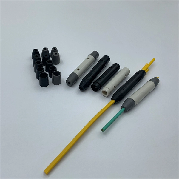
These connectors have a universal termination kit that includes all the components needed for installation. The instructions provided describe the assembly procedure for installing the connectors, including identifying the components, preparing the fiber, and assembling. FASTConnect® field-installable connectors are factory pre-polished connectors that completely eliminate the need for hand polishing in the field. Proven mechanical splice technology ensuring precision fiber alignment, a factory pre-cleaved fiber stub and a proprietary index-matching gel combine to. Comes in a pack of 6 connectors. Comparable to OCC part number FXC-ST8-6 and Corning part number 95-200-51. FAST Connectors are compatible with 250 µm and 900 µm optical fibers, as well as 4. 8 mm (SC only) cordage. A factory-installed wedge clip (included. FAST Connectors are designed for use with single-mode or multimode fiber optic cable and come in SC, ST, and LC configurations. ead these instructions carefully before proceeding. Different termination options after cleaving the fiber are provided for each fiber type ys wear eye protection.
[PDF]
This report offers comprehensive insights, helping businesses understand market dynamics and make informed decisions. Do you also provide customisation in the market study? Yes, we provide customisation as per your requirements. To learn more, feel free to contact us on. How does 6W market outlook report help businesses in making decisions? 6W monitors the market across 60+ countries Globally, publishing an annual market outlook report that analyses trends, key drivers, Size, Volume, Revenue, opportunities, and market segments. This report offers comprehensive. Exports In 2022, Sierra Leone exported $20. 1k in High-voltage Protection Equipment, making it the 126th largest exporter of High-voltage Protection Equipment in the world.
[PDF]