For singlemode fiber, the loss is about 0. 5 dB per km for 1310 nm sources, 0. 5 dB/km at either wavelength for outside plant max per EIA/TIA 568)This roughly translates into a loss of 0. 1 dB per. ity check. The fiber optic link attenuation is tested using an optical loss test set (OLTS) or a light source and power meter (LSPM) Figure 1). This type of testing is the most accurate testing available and is the most accurate characterization of the fiber optic system's apability. The estimate, called a "loss budget" is calculated using typical component losses for. Many solutions for 100 Gbit/s Ethernet have proposed to use CWDM to carry the multiple lanes over separate wavelengths on a single fibre. The presentation from Monterey anslow_01_0107. wavelength to justify the choice of CWDM channels to be analysed. It was. This document outlines the specifications for a single-mode optical fiber and cable designed for use around the 1310 nm zero-dispersion wavelength, suitable for both the 1310 nm and 1550 nm regions, and compatible with analogue and digital transmission. The acceptable dB loss for single mode fiber can vary depending on several factors. Measured in decibels (dB), insertion loss is the reduction in signal power that happens along any length of cable for any type of transmission. The longer the cable, the more a signal is reduced (or attenuated) by the time it reaches the far end. In addition to length, events that cause reflections.
[PDF]
The devices has a wide pass band, low insertion loss, high channel isolation and excellent environmental stability. Channel numbers can be as high as 40 (16) for 100 (200)GHZ systems in C band or in L band. They can be used in DWDM systems to perform a multiplexing or. Fiberdyne Labs offers Dense Wavelength Division Multiplexer (DWDM) Modules in a wide variety of formats. While Fiberdyne offers some models as "standard," we will also produce customized DWDM modules. Customization can include the number and selection of DWDM channels. Channel. AFL's DWDM LGX modules provide scalable wavelength management for new deployments and network upgrades, providing increased bandwidth over a single common fiber. Based on thin film filter technology, the device is less than one-third the size of traditional cascaded DWDMs of similar channel count. Modules can be installed in standard LGX chassis and are available with LC bulkheads in select. All parameters are for device without connectors 2. Special specifications can be customized according to customer requirements DWDM mux demux and optical modules for high-capacity fiber networks. 40/80-channel options, rack mount or LGX type, low insertion loss, high stability. Ideal for telecom.
[PDF]
ITU & IEC allow 0. 75 dB loss per mated pair. Splitter loss values are "Typical" and include a connector in and out. These values are approximate and should not be exceeded by more than 1-1. 5 dB, which could indicate dirty connectors, bad splices . ITU & IEC allow 0. Passive split links usually lose the most dB at the splitter, so we keep the optical budget and the installed route separate. Measured in feet for imperial mode. Drop length Adds. Calculate split loss, excess loss, and terminations for any ratio quickly today. See power budget impact instantly, then download a CSV or PDF summary. Use 2×N when two inputs feed the same distribution stage. Common values: 2, 4, 8, 16, 32, 64. Abridged Optics — Beam Splitter Calculatorv1. 0Fresnel calculations assume a single uncoated interface. Real beam splitters use multi-layer coatings that modify R/T beyond Fresnel predictions. Understanding the types of splitters, their impact on network performance, and how to measure their losses ensures high-quality network operation and facilitates optimal splitter selection based on. This value should be determined by the system designer. 3 recommends a maximum value of 0. Total Splice Loss (The maximum splice loss permitted for installation. Components, such as fiber cables, splitters, and switches, introduce attenuation.
[PDF]
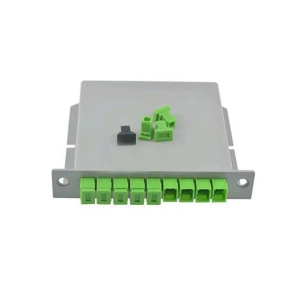
This article provides an in-depth exploration of OSFP copper cable technologies, including DAC, ACC, and AEC, with a focus on 400GB NDR splitter cable applications. Whether the signal is propagated by copper wire, optical fiber, Wi-Fi, or just yelling at the kids down the street, the signal is never as strong at the destination as it is at the source. In the case of physical voice communication, the kids will understand you if they are close-by. If they are. Insertion loss and attenuation are similar concepts, but one is assigned to a single component (insertion loss) whereas the other is assigned to generalized performance (attenuation). Both terms refer to a measurement comparing the signal strength received against a transmitted signal. Standard. Channel Master TV splitters are designed to equally divide the signals on the input port of the splitter to each of the output ports of the splitter. This. Insertion loss is the amount of energy that a signal loses as it travels along a cable link. It is a natural phenomenon that occurs for any type of transmission—whether it's electricity or data. This reduction of signal, also called attenuation, is directly related to the length of a cable—the. In fiber-optic networks like FTTx and PON, PLC splitters are key components for distributing optical signals to multiple users. However, each splitter has complex parameters, including insertion loss, return loss, polarization-dependent loss, and uniformity.
[PDF]
This application note explains how Site Master is used to measure cable insertion loss with different test methods and how to predict the maximum allowable cable insertion loss through manual calculations. Desktop Insertion Return Loss Tester with color screen has stable and reliable performance, which integrates stable light source, high-precision power meter, insertion loss meter and return loss meter into one multifunction instrument. Based on domestic customers'. Modern handheld analyzers, like the Keysight FieldFox Analysers, are designed specifically for cable and antenna testing (CAT), offering fast and accurate insertion loss testing across a wide frequency range. These tools are invaluable for both installation and maintenance, enabling field. Insertion loss is expressed in decibels or dB. The decibel is a logarithmic expression of the ratio of output voltage (voltage of the signal received at the end of the link) divided by input voltage (the voltage launched into the cable by the transmitter). 0 PCB transmission line losses in a PCB production environment. In wireless communication systems, the transmit and receive antennas are connected to the.
[PDF]
Cold joints occur when there's an unintended interruption in the concrete pouring process. This results in weak seams where the two layers fail to chemically bond. Unlike construction joints, which are reinforced and planned, cold joints are structural defects that require immediate. A cold joint in concrete construction is a plane of weakness that forms when new, wet concrete is poured against concrete that has already begun to harden. They can be a real pain, potentially leading to structural issues down the line. Time to break down the details. The term "cold" is used because the two concrete layers are not bonded properly, which can result in a weakened. Few defects pose a more immediate and insidious threat to the long-term performance and intended load-transfer characteristics of a structure than cold joints in concrete columns. While often dismissed as purely aesthetic blemishes, a cold joint is, fundamentally, a failure of integration—a plane. Cold joint concrete is a common problem in the construction world. It's important for construction professionals to understand what causes cold joints and how to manage them effectively. This article takes a closer look.
[PDF]
The optical budget refers to the maximum allowable signal loss between the transmitter and receiver in a fiber-optic link. It ensures that the received signal is strong enough for the equipment to process data without errors. Calculated in decibels (dB), it is the difference between the. After measuring the loss of a fiber link, you now have to determine if that fiber link loss is acceptable or not. You can either compare this loss value to the application requirement or calculate the expected loss based on how many connectors and splices are in the link along with the length of. Optical module channel loss resistance refers to the maximum optical path attenuation that an optical transceiver module can tolerate while still maintaining compliant signal integrity, error performance, and link stability. There are many reasons for optical fiber loss, such as optical fiber material's absorption/scattering of light energy, bending.
[PDF]
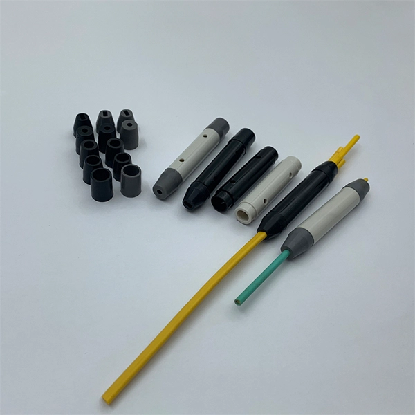
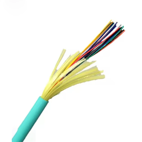
Built with OS2 singlemode fiber, it ensures ultra-low insertion loss and excellent return loss, providing stable transmission over long distances. unk cables connect central patching locations to zones or pods. Available terminated with both modular (MPO) and discrete connectors, these trun s are custom built in any length to meet specific applications. An optional pulling eye, installed on the first end, rotects fiber connectors on 12-. The OS2 Singlemode Simplex LC/SC/FC/ST Armored Fiber Optic Pigtail from Fiber-Life is designed for reliable and durable fiber terminations in demanding network environments. GYTA53 Double-Layer Armored Stranded Structure, Customizable 4-288 Fiber Cores. Fully compatible with mainstream devices worldwide, precisely matching single-mode optical fibers, and enabling rapid project implementation. This reliable fiber pigtail cable comes with a pre-terminated connector on one end—ready for immediate. Armored pigtails from FiberZON. com - worldwide supplier in fiber optic solutions, optical network, FTTx, fiber testing, fiber cables & tools.
[PDF]
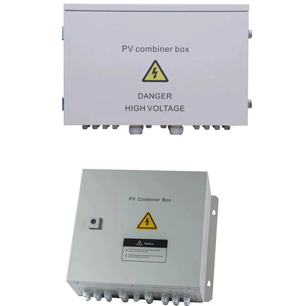
Buyers typically pay a broad range for replacing a distribution box, driven by box size, amperage, wiring runs, and local labor rates. This article outlines the cost factors, price ranges, and practical budgeting advice for a U. In the world of electrical contracting, you have to estimate and submit bids in order to win projects and stay in business. This means bidding low enough to win against many competing electrical contractors, while high enough to cover all the project costs like labor, material, equipment. As an electrical contractor, you must account for materials, labor, subcontractors, and equipment while ensuring costs stay within budget and deadlines are met. Electrical estimating involves reviewing project specifications, calculating material quantities, considering overhead, turnkey estimates. Estimating electrical work — particularly in the context of new construction projects or extensive commercial service jobs — involves many steps and moving pieces. Whether you're quoting a panel upgrade or a full-scale buildout, every detail in your estimate shapes the bottom line. Create professional electrical project estimates with localized material pricing, labor rates, and tax calculations. Supports US (USD), Canada (CAD), and UK (GBP) markets with region-specific electrical components and standards. Accurate cost estimating is essential for profitable electrical work. Understanding cost components helps avoid surprises in.
[PDF]