ShowMeCables offers a wide selection of LMR-600® thick low loss cables for long-distance runs. These LMR-600 cables are designed with flexibility, low loss and RF shielding with options such as ultra-flex, weatherproof and fire retardant rating for safe indoor, outdoor, or direct. TC-240-FM-X 3190-2891 <1. N Male Straight Plug 3. 35:1 (6) Hex/Knurl Solder Crimp A/G 1. Since 1975 delivering the world the best copper and copper alloy products to build a more connected, clean and efficient planet. is a Peruvian manufacturer that specializes in the design and production of electrical cables and conductors made from copper and aluminum for low and medium voltage applications. These. Check each product page for other buying options. Alligator Clips Electrical with Wires UL1015/18AWG, 6 Colors Jumper Test Leads Set, 1. Clips Soldered with Wires- EDGELEC Need help?. Our wire and cables have been helping real, hardworking pros on the job for more than 45 years. Their success is our success. Direct Wire is widely known as the market leader for highly durable and versatile cables and assemblies manufactured to stringent U. and international standards.
[PDF]
In this video, we'll walk you through the process of wiring a home distribution box with a detailed connection diagram. Whether you're an electrician or a DIY enthusiast, this guide will help you understand the basics of home electrical distribution. more Welcome to our channel! In this video. Understanding the wiring diagram of an electrical panel box is essential for electricians and homeowners alike, as it allows them to troubleshoot any electrical issues, carry out repairs, or make additions to the system. The electrical panel box wiring diagram provides a visual representation of. A distribution board or distribution box is where the main power supply is distributed to multiple loads. And all the switching and protective devices are installed in the distribution box. Single Phase Distribution Box generally consists of Double Pole MCBs, Single Pole MCBs, and RCCBs. Connect the two hot conductors (typically black and red) to the line terminals of the main disconnect switch. Tighten each lug to 250 inch-pounds using a torque wrench. What is Distribution Board? Distribution board.
[PDF]

Thinner cables can be utilized to connect the control switch to the relay; this saves space, weight, and cost. The same voltage and current ratings as other types of switches, such as mechanical switches, do not limit relays. This handbook covers the code of practice in protection circuitry including standard lead and device numbers, mode of connections at terminal strips, colour codes in multicore cables, dos and donts in execution. Also principles of various protective relays and schemes including special protection. A control relay is an electrically operated switch that enables current to flow through a coil that closes or opens the switch. Relays use a small current to control a larger current, making them ideal for controlling high-power devices such as motors, lights, valves, and sensors. When a relay contact is open, this will switch power ON for a circuit when the coil is activated. You'll connect a low-power control circuit to the relay's coil (terminals 85 and 86), which then flips a switch for a separate, high-power circuit running through the. Electrical protection relay has two type protecton as HT panel protection and LT panel protection. HT panel protection relay. The HT power supply is received from GO switch and distributed to the. The rectangular devices are test connection blocks, used for testing and isolation of instrument transformer circuits. : 4 The first protective relays were electromagnetic.
[PDF]
This guide will provide you with a detailed Cat 6 socket wiring diagram, outlining the necessary steps and components required for a successful installation. If you want to install a classic network socket, you must first strip the Cat. A special stripping tool for data cables is used here – for example, the Stripper No. Use side A to remove the protective jacket. 35, you can shorten the network cable (Cat. 7) a little bit, if required. If you have too much cable left, it will be harder to. Learn how to wire a distribution box step by step! This video shows real on-site footage of electrical installation, demonstrating safe and standardized wiring methods used by professionals. 5mm² wires, and the air conditioning circuit can use 2. Connection method: Each switch takes a wire from the incoming point and connects it to the incoming end of the switch, or uses parallel connection to reduce the difficulty. Learn how to install a distribution box safely and correctly. Covers wiring, placement, standards, and expert tips for a compliant setup. A distribution box is the heart of any electrical system. It takes the incoming power and safely distributes it to different circuits throughout your building. Understanding the wiring diagram of an electrical panel box is essential for electricians and homeowners alike, as it allows them to troubleshoot any electrical issues, carry out repairs, or make additions to the system.
[PDF]
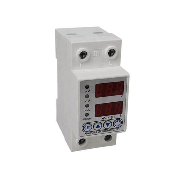
Live (L) Wire Connection: In a distribution box setup, the incoming live wire (also known as phase or hot wire, denoted as L or Line) connects to the line terminal of the circuit breaker. This serves as the primary source of electrical energy from the mains supply. Correct wiring methods for circuit breakers within distribution boxes are fundamental to ensuring electrical safety and compliance with established codes. The distinction between 1P and 2P circuit breakers plays a pivotal role in determining the appropriate protection level for various circuits. And all the switching and protective devices are installed in the distribution box. Single Phase Distribution Box generally consists of Double Pole MCBs, Single Pole MCBs, and RCCBs. The wire neutral is the return line in an electrical system that brings current from the electrical equipment back to the transformer or distribution box, completing the loop closure of the current. Figure 2-3 What wire is neutral? What does the neutral wire do? Although the neutral wire is usually. Live wires carry the power from the source to a switch or appliance. These may be light switches, electrical outlets, or junction boxes for light fixtures. The live wire is always under voltage, meaning it carries the. The main service panel, also known as the breaker box, is the central distribution point for the home's electrical system.
[PDF]
This video shows real on-site footage of electrical installation, demonstrating safe and standardized wiring methods used by professionals. more Learn how to wire a distribution box step by step! This video shows real on-site footage of. A ddc panel wiring diagram provides a visual representation of the connections and wiring between the ddc panel and other components in the building automation system. It includes information about the various input and output points, the power supply, and the communication channels. A. A distribution box is the heart of any electrical system. It takes the incoming power and safely distributes it to different circuits throughout your building. Whether in a home or an industrial facility, this box keeps your electrical setup organized, functional, and efficient. This section will explain its function, types, and the importance of correct. A facility's direct digital controls (DDCs) form a living, breathing system that an owner will use throughout the life of the building. However, many control systems do not work as designed on “Day One,” much less after two to three years of use. Adding to the complexity are subcontractors, who. Strictly speaking, the word “Distribution Box (D-box)” can refer to two categories: electrical distribution boxes and septic tank distribution boxes. This article mainly talks about the first one. An electrical distribution box, also known as a power distribution box, panelboard, or consumer unit.
[PDF]
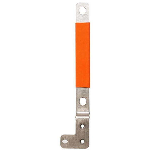
On the US market, a 5. 26 mm 2 (10 AWG) ground wire must be used, and in all other markets a 6 mm 2 must be used. Grounding of the units: Attach a ground wire from one of the threaded studs (A) at the bottom of the housing, to the mounting plate (B). Attach a second grounding wire from the mounting. The correct connection method of Distribution box grounding wire mainly includes the following steps: 1. Find the grounding bar or PE bar Open the distribution box and find the position marked with the grounding plate or PE letter. The basic rule achieves this through an equipment grounding jumper; four exceptions. An equipment grounding conductor passing through the box without a splice is not required to be joined inside the box to others that are spliced in the box. 148 addresses the continuity of equipment grounding conductors and their attachment in boxes. Not all boxes are metal or provide. Correct grounding of services depends upon understanding the definition and role of the grounded conductor. The neutral conductor is typically the grounded conductor connected to the system's neutral point, carrying current under normal operation. Whether you're a seasoned pro or just starting out, this comprehensive guide will give you practical.
[PDF]
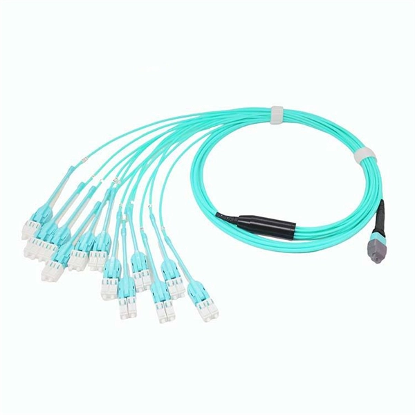
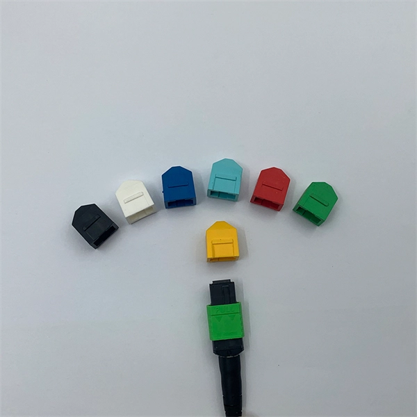
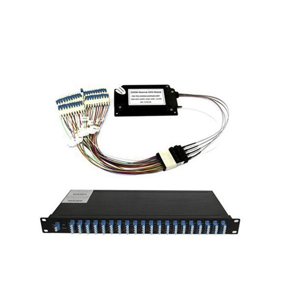
Fiber optic patch cables are ideal for supporting high speed telecommunication network fiber applications. They are manufactured and tested in compliance with TIA 604 (FOCIS), IEC 61754 and YD/T industry s.
[PDF]
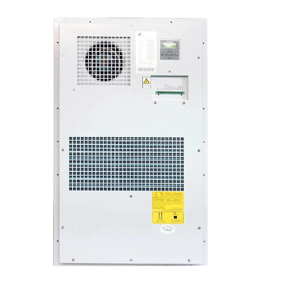
The XL-21 type low-voltage power distribution cabinet is an indoor fixed enclosed complete set of equipment that complies with IEC 60439-1 and GB 7251. It is specially designed for 50Hz AC power distribution systems with a rated voltage of 380V/660V and a rated current of. Standard Type (P Type): This version has a cabinet height of 1700mm or 1800mm and is designed for independent installation. It can be equipped with entry and exit holes at the top as required. Busbar Type (M Type): This version features a cabinet height of 1900mm or more, with a removable cover on. The Fulleto XL-21 series is an indoor, floor-standing power distribution cabinet engineered for excellence. It serves as the central hub for receiving and distributing electrical energy in low-voltage systems up to 380V. Designed for power plants, substations, industrial enterprises, and commercial. The XL-21 Power Distribution Box is used for power distribution, conversion, transmission, control, and on-site operations in low-voltage distribution systems. It is widely applied in power plants, substations, petroleum, chemical, metallurgy, machinery, and high-rise buildings. The XL-21 Power. The XL-21 type power distribution cabinet is a crucial component in electrical systems, designed to distribute power efficiently and safely across various industrial and commercial applications.
[PDF]
Customers close to a distribution transformer are able to have service drops directly connected to transformer secondary connections. Other customers are reached by routing a secondary main for servic.
[PDF]
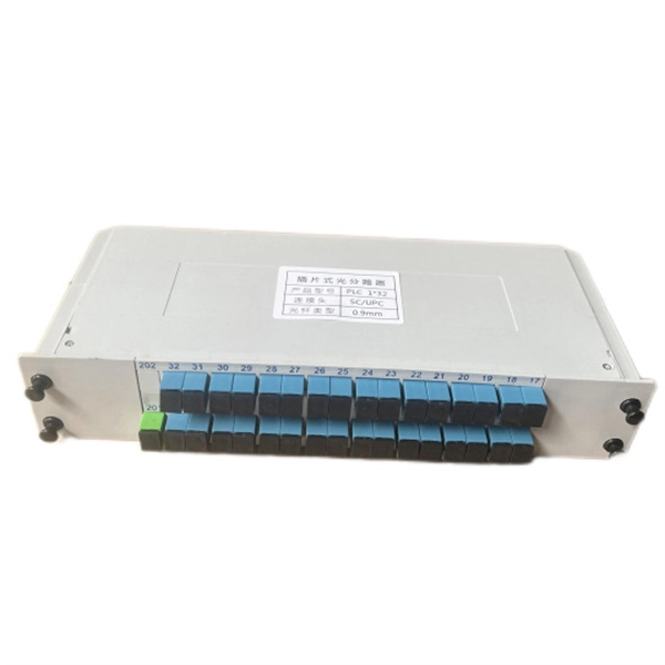
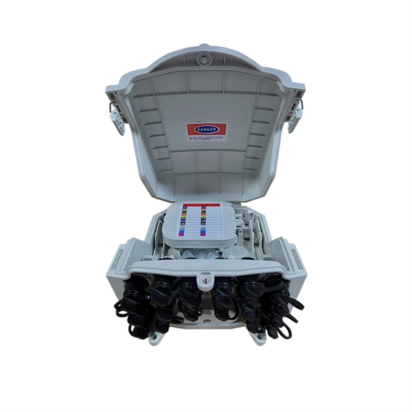
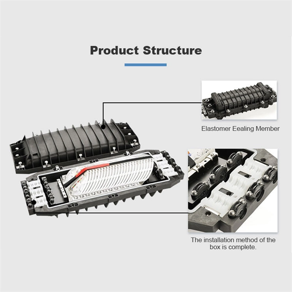
Our products cover MPO connectors, optical time-domain reflectometers (OTDR), optical cable joint boxes, optical fiber distribution boxes, optical cable cross-connect cabinets, etc. We provide comprehensive optical communication solutions and are a professional optical fiber. Haian Guangyi Communication Technology Co. specializes in manufacturing a full range of passive optical components, including optical splitters, optical fiber connectors, ODN products, and optical communication test instruments. These sequences are similar to bacterial DNA and are recognized by Toll-like receptor 9 (TLR9), an essential component of the innate immune. ODU series ODF sub-rack could be classified to integrated splicing & termination sub-rack and separated splicing & termination sub-rack. It usually is used in ODF rack or other telecommunication cabinets. ) specializes in providing the complete FTTH Product Series, ensuring that every decibel of optical power is preserved from the core to the customer. A standard FTTH ODN is divided into four critical segments. Weunion provides. CpG oligodeoxynucleotides (CpG ODNs) are synthetic DNA molecules characterized by short, single-stranded structures containing unmethylated CpG motifs derived from bacterial DNA. Pre-clinical studies and trials have demonstrated that CpG ODNs can significantly improve vaccine-specific antibody responses. CpG ODNs possess a partial or complete phosphorothioate.
[PDF]
This post is a step-by-step detailed installation guide on how to run wires for security cameras to help you install security camera wiring for both indoors and outdoors. Proper wiring is crucial to ensuring that your security cameras function effectively and provide clear, uninterrupted footage. How to connect your cameras and recorder to provide power and a video feed, including for remote viewing via smartphones and computers. We always recommend wired systems when possible. We offer two different types of wired security camera systems -. There are two different ways to install security camera wiring: POE security camera wiring and wireless security camera wiring. Whether you're securing your home or business, the quality and installation of your camera wiring play a crucial role in ensuring consistent, high-quality video feeds. In this guide, we. This article provides a detailed principle explanation of 3R methods (reamplification, reshaping, and retiming) to reach the extension of passive optical networks. The second part of the article focuses on optical amplifiers, their advantages and disadvantages, deployment, and principles. We. In this step-by-step guide, we will walk you through the process of wiring your 2 wire security camera, providing you with a clear understanding of the necessary steps and a helpful diagram to refer to.
[PDF]
In this video, we'll walk you through the process of wiring a home distribution box with a detailed connection diagram. Whether you're an electrician or a DIY enthusiast, this guide will help you understand the basics of home electrical distribution. more Welcome to our channel! In this video. A distribution board or distribution box is where the main power supply is distributed to multiple loads. And all the switching and protective devices are installed in the distribution box. Single Phase Distribution Box generally consists of Double Pole MCBs, Single Pole MCBs, and RCCBs. Single Phase wiring installation is the most common wiring in residential buildings. It is essential for managing the electrical supply to various appliances and circuits in the building. Its function is to safely divide the incoming high-amperage utility power into smaller, manageable branch circuits that supply power to lights, outlets, and.
[PDF]
This video goes over common types of connectors, their respective adapters, and how to properly connect and disconnect them. For your safety, it is always advised to follow proper fiber optic handling techniques and utilize the correct protective gear when performing. Fiber optic adapters, also known as couplers, play a crucial role in fiber optic networks by providing a connection point between two fiber optic connectors. They enable seamless and reliable optical signal transmission between different fiber optic cables, connectors, or devices. In this tutorial. Proper connection of fiber optic cables is essential to harness these benefits fully, as even minor errors can lead to significant performance issues like signal loss. more Are you interested in seeing how fiber optic connectors get. Vigitron's Vi5004 is a 4-port fiber optic media convertor that enables Ethernet signals to be transmitted over fiber optic cables. It enable UTP Ethernet to connect to fiber to meet long distance transmission requirement or where fiber is already installed. Why Use Fiber Optic Internet? Before diving into the setup, let's quickly recap why fiber optics are worth the effort: Lightning-fast speeds (up to 1 Gbps or higher). Low latency for.
[PDF]
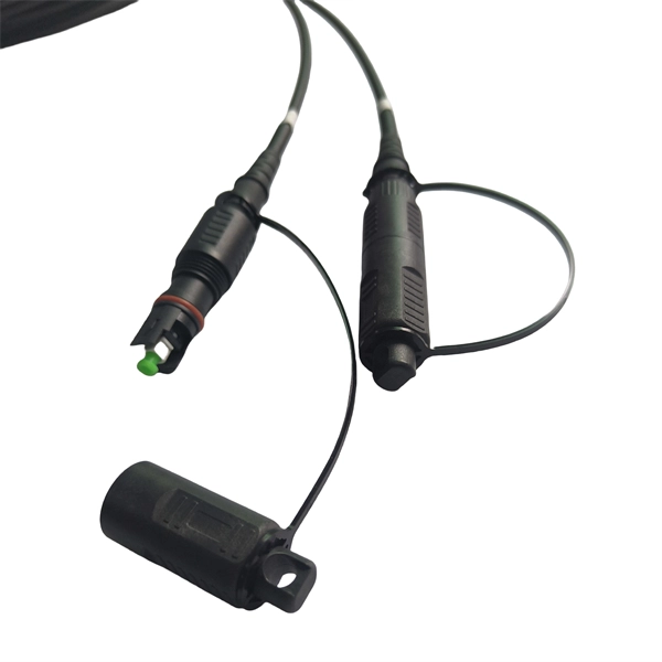
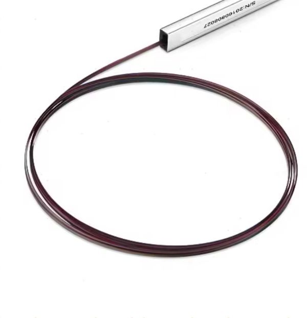
Learn the key difference between pigtail and jumper cables: only one end of a pigtail connects, while both ends of a jumper feature connectors. Similar to coaxial cable, but without mesh shielding, for jumper. When it comes to fiber optics, we naturally think of patch cords and pigtails. Usually people don't know the difference between the two. Let's find out together. Carrier-grade single-mode fiber patch. The Fiber Optic Patch Cord, also referred to as a fiber optic patch cable or fiber jumper, is a specialized cable designed for transmitting data signals using light waves in fiber optic communication systems. It is worth noting that fiber pigtails and patch cords are not the same concept. The main difference between fiber optic patch cords and fiber optic pigtails is that only one end of the fiber optic pigtail has an active connector, and both ends of. Jumper cables and portable jumper boxes are both tools used to revive a vehicle with a dead battery, but they have distinct differences despite sharing a similar end-goal. And with a plethora of purchasable options in both camps, it can be difficult to decide which way to spend your pretty pennies.
[PDF]