Fiber Connection: Locate the optical port on your router and carefully insert the fiber cable's connector, ensuring a snug fit. Click it into place if it has a locking mechanism. Power Up: Connect the power cords to your router and any additional devices (ONT, media converter) and. Proper connection of fiber optic cables is essential to harness these benefits fully, as even minor errors can lead to significant performance issues like signal loss. This article will guide you through the necessary tools, materials, and methods on how to connect fiber optic cables effectively. Fiber optic internet delivers blazing-fast speeds and reliable connectivity, making it a top choice for modern homes and businesses. However, setting up a fiber optic connection to your router can seem daunting if you're unfamiliar with the process. Before you start, gather the right tools. You don't want to dig around mid-job for something small but essential. Each tool helps you protect the fiber. The process to connect fiber optic cable to router requires careful attention to detail, but I'll walk you through every critical step with the precision and clarity you deserve. The fiber. The process involves a combination of national infrastructure, local engineering, and property-level setup. In this guide, we'll break down the fiber installation process from start to finish and explain key components such as fiber cabinets, flower pods, ducting, and ONT setup. What Is Fiber Optic.
[PDF]
This document describes how to use and program the Photonic Application Suite, Insertion Loss Engine. Insertion loss is measured by comparing signal power (or sound level) before and after it passes through a component or system, then expressing the difference in decibels (dB). The core process is the same across fiber optics, RF electronics, and acoustics: establish a baseline reference without. This tutorial aims to help RF engineers understand how to test and measure various RF specifications of RF power amplifiers, RF LNAs (Low-Noise Amplifiers), and RF transceivers using RF test and measurement equipment like spectrum analyzers, signal generators, and sweep oscillators. Gain is the. Coaxial cables are essential components in transmitting radio frequency (RF) signals, but they inherently attenuate these signals, a phenomenon known as cable loss or insertion loss. Yes, I would like to receive educational or promotional emails from Keysight. By clicking the button, you. Insertion loss is a critical parameter in RF engineering that refers to the loss of signal power that occurs when a component or device is inserted into a transmission line or circuit. The insertion loss measurement quantifies the effect of the resistance the cabling link offers to the transmission of the electrical signals. Insertion loss characteristics of a.
[PDF]
Picking up the best router for fiber internet isn't just about going to the market and choosing one of the best wireless routers. Instead, you need to carefully look at its specs, performance, and the type of securit.
[PDF]
This document provides the users of USB4000 Spectrometers with instructions for setting up, calibrating and performing experiments with their spectrometer. Remote fiber optic spectroscopy is a sophisticated technique that uses fiber optic couplers, cables, and accessories to analyze samples at a distance from the spectrophotometer. The technique unlocks a range of experiments that standard UV-Vis or fluorescence instruments cannot accommodate. The. Fiber optic spectrometers have revolutionized the field of remote sensing and data acquisition, providing unprecedented flexibility and precision. These devices utilize the unique properties of fiber optics to measure and analyze the spectral composition of light, making them indispensable tools in. The Cary 60 Fiber Optic Coupler and the Cary 60 Dip Probe Coupler are optional accessories for the Cary 60 UV-Vis spectrophotometer. Both accessories convert the Cary 60 UV-Vis into a remote fiber optic measurement system. Contains descriptive. Near-Infrared Spectroscopy (NIR) offers important advantages in analytical chemistry, particularly in process monitoring and quality control across various industries. This paper details the operational principles, methodologies, and significant advancements in NIR spectroscopy, emphasizing the. The basics of fiber optic cables and bundles and how they can be used to collect and direct light are discussed in 'An Introduction to a Spectrometer: Fiber Optic Bundles'.
[PDF]
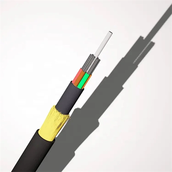
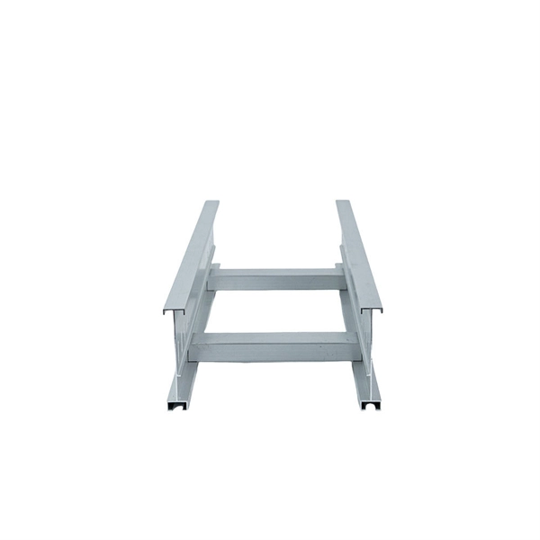
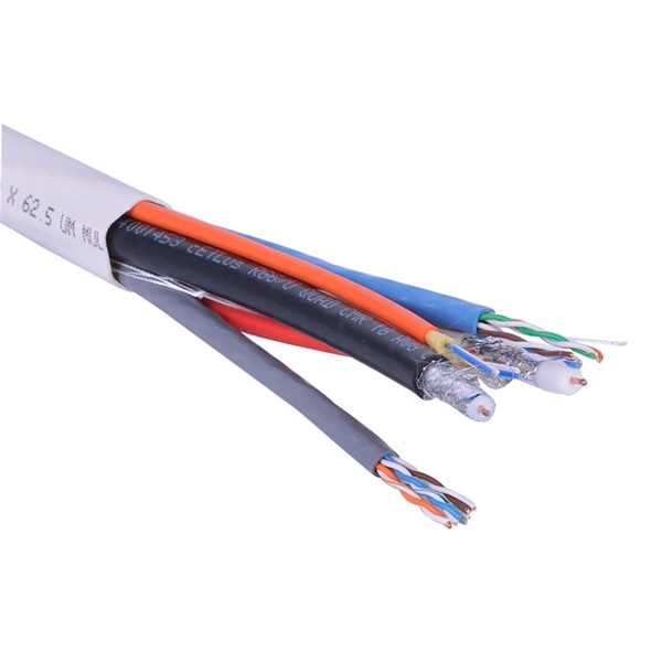
Flexi ZWP is a single mode fiber that has low water peak sattenuation and low optical losses in the entire bandwidth range. The two layers of acrylate coating enhances the fiber reliability and is of specific use in high-speed data transmission needs. Recommendation ITU-T G. 652 describes the geometrical, mechanical and transmission attributes of a single-mode optical fibre and cable which has zero-dispersion wavelength around 1310 nm. 652 fibre was originally optimized for use in the 1310 nm wavelength region, but can also be used in. gh modulus plastic. The tubes are filled with a water-resistant filling compound. A Fiber Reinfor ed Plastic (FRP) locates in the center of core as a non-metallic strength member. The cable core is. G. Whether it is a long-distance network, local network, or access network, it is the absolute protagonist, accounting for more than 95% of its overall. Optical Fiber (OF) forms the core of any OFC product, and HFCL is proud to be one of the finest producers of high-quality and multi-configuration Optical Fiber. HFCL facility manufacturing Optical Fiber houses the latest cutting-edge machinery delivering premium products, enabling HFCL to maintain. There are 19 different single mode optical fiber specifications defined by the ITU-T, among which G. 652 fiber is the most commonly used. 652 Fiber? Among all the single mode fiber types, G.
[PDF]
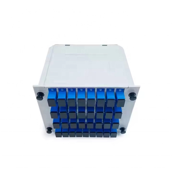
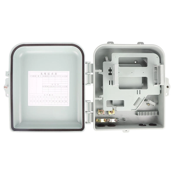
This complete guide explores everything you need to know about ODFs — from their structure, types, and key components, to installation best practices and modern design trends. Whether you're building a central office, data center, or FTTx distribution network, understanding the right ODF. In the complex architecture of fiber optic networks, the Optical Distribution Frame (ODF) serves as the linchpin for organizing, protecting, and distributing optical signals. It's where incoming and outgoing cables meet. It does four key things: Think of it as the central hub for your fiber network. Without it, cables get tangled. All. How to Splice 4-Fiber Optic Cable with ODF | Step-by-Step Fiber Optic Splicing Tutorial. Whether you are a beginner or a professional in fiber optic networking, this guide will help you splice. Fiber Optic Infrastructure Specialist (19Y Exp) | One-Stop: Fiber Cables, Distribution Boxes, Splice Closures, Splitters & Patch Cords | Sourcing for ISPs & Contractors in EU/Africa. It is used to terminate, connect, and distribute optical fibers, and it can be installed in various environments such as data centers, telecom rooms, and central offices. In this article.
[PDF]
Picking up the best router for fiber internet isn't just about going to the market and choosing one of the best wireless routers. Instead, you need to carefully look at its specs, performance, and the type of securit.
[PDF]
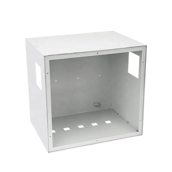
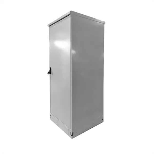
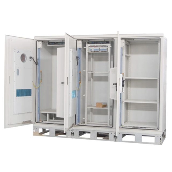
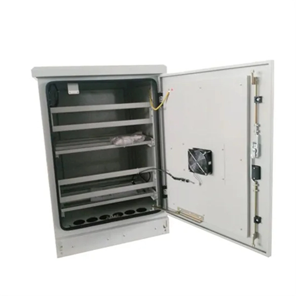
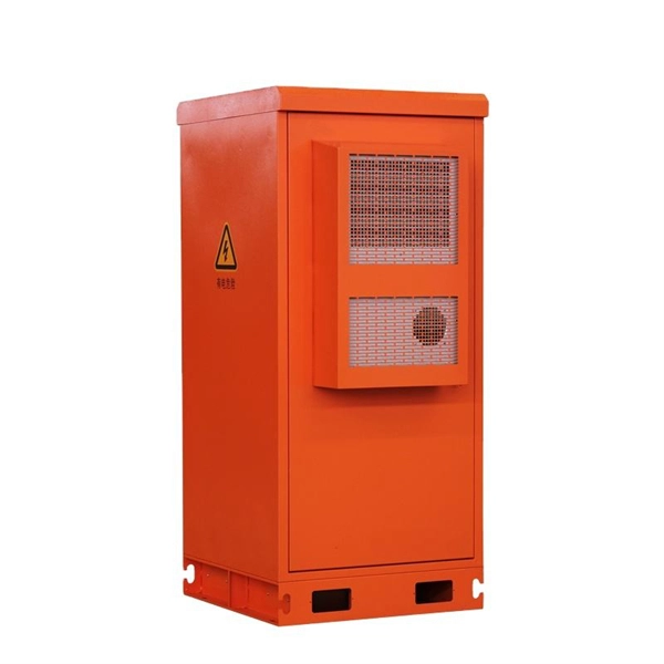
The main switch, or main breaker, controls the entire electrical supply to the distribution box. This large switch allows you to disconnect all power to the building during emergencies or maintenance work. It's typically rated for the maximum current capacity of the electrical. Isolation switches in distribution boxes ensure electrical safety by disconnecting circuits for maintenance, preventing shocks, aiding compliance, and improving system reliability. What Is an Isolation Switch? An isolation switch (also called an isolator or disconnector) is a device that separates. Messy distribution boxes are dangerous and very hard to fix. You will learn to build a safe, efficient, and professional electrical system today. Unlike circuit breakers that protect against overloads and short. As the main switch is separated from the whole distribution box, it can also be used as the power supply terminal (including bus bar) for the protection function of switching, and can also be used as the backup protection circuit of feeder. Switchboards typically have a maximum voltage rating of 600 Vac/Vdc and a. A distribution box, also known as a distribution board, electrical panel, or breaker box, is an enclosure that houses electrical components responsible for distributing electricity throughout a building. It receives power from the main electrical supply and divides it into separate circuits, each.
[PDF]
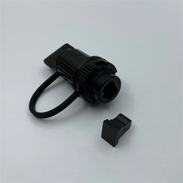
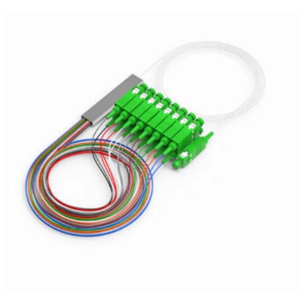
This interactive tutorial explores transmission and reflection of a light beam by three common beamsplitter designs. In addition to the task of dividing light, beamsplitters can be employed to recombine two separate light beams or images into a single path. The tutorial initializes with a cube. The fiber jumper connects the network devices at both ends and is used in the following three scenarios. FC Connector: use a metal sleeve for external reinforcement, fastened with a screw fastener. Generally used in the ODF (the most used on MDF) SC Connector: connected to the GBIC module, its. As title. It is a crucial part of many optical experimental and measurement systems, such as interferometers, also finding widespread application in fibre optic telecommunications. In its. The beam splitter has played numerous roles in many aspects of optics. For example, in quantum information the beam splitter plays essential roles in teleportation, bell measure-ments, entanglement and in fundamental studies of the photon. Electric elds E1 and E2 enter input ports 1 and 2. A beam splitter is an optical device that splits beams (such as laser beams) into two (or more) beams. Beam splitters typically come in the form of a reflective device that can split beams into exactly 50/50, half of the beam being transmitted through the splitter and half being reflected.
[PDF]
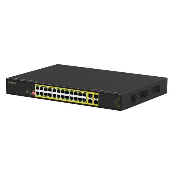
The Huawei OEGD01N01 is an Optical Functional Module known for its robust functionality in networking environments. It is a 1000BASE-T-SFP Module featuring an RJ45 Electrical Module with auto-negotiation capabilities. Optical modules are widely used in switches, network interface cards (NICs), routers, and other communication devices. During use, reading optical module information helps understand its real-time operating status, enabling faster troubleshooting of link abnormalities. The following uses the. A switch must use optical or copper modules that have been certified for use on Huawei switches. Non-certified optical or copper modules cannot ensure transmission reliability and may affect service stability. Designed for optimal performance, it supports a longest transmission distance of. OLT is the world's first Terabit fiber access system. With the pending support for XG-PON1 (10Gbps downstream and 2. 5Gbps upstream data rates) technology, Huawei's MA5600T OLT is designed to provide even higher subscriber bandwidth in shared fiber splitter applications. Huawei's all-in-one fiber. TX/RX power test ensures that the optical power are within the thresholds; remove the aged optical module with power loss, and the fake module with counterfeit label. Huawei is not liable for any problem caused by the use of non-certified optical or.
[PDF]
One of the first indicators that a fiber optic patch cord needs replacing is an increase in signal loss. Over time, various factors can contribute to this decline in performance, including wear and tear, contamination, and environmental influences. Fiber optic patch cords are essential components in modern communication systems. Understanding their lifecycle can help users make informed decisions about their selection, maintenance, and disposal. This article delves into the various stages of fiber optic patch cords, ensuring that readers. Effective lifecycle management of fiber optic cables, from selection and installation to daily maintenance and replacement, is essential. " The reality is more nuanced: silica The optical core is virtually chemically indestructible, but the sheaths, coatings, and. When you invest millions in a fiber optic cable network, you are buying a long-term asset. The industry standard says Fiber Optic Cable Lifespan should last 25 years. But ask any veteran network engineer, and they will tell you a different story. Some fiber optic cables fail in 5 years, turning. Key Risks and How to Fiber-optic cables are the backbone of modern connectivity—powering 5G networks, global internet backbones, and data center interconnections with near-light-speed data transmission. In this blog post, I will share valuable insights into the importance of.
[PDF]
You can test a photocoupler with a multimeter. This checks if its output changes when you power its input. This gives you the most accurate test results. This detailed guide will walk you through the process of testing an optocoupler using a multimeter, covering various scenarios and providing practical advice to ensure accurate results and avoid common pitfalls. We'll explore the underlying principles, delve into different testing methods, and. In this episode #0018 of Electronic Components Testing, we reveal how to test an optocoupler (optoisolator) using a digital multimeter step by step. This simple yet powerful technique will help you detect faulty optocouplers on circuit boards without desoldering them. Always. What are the methods to test optocoupler? The quality of the optocoupler can be determined by measuring the forward and reverse resistance of its internal diode and triode. Jotrin Electronics Limited will tell you that the reliable detection methods,as follows: 1. From basic circuit design to complex industrial systems, accurate optocoupler. Optocoupler is one type of ICs, It isolates input and output section by using optical technology this feature increase safety of circuit. Optocoupler has many part number, different part number has different output type so before checking it has to use part number to research with datasheet and.
[PDF]
A spectrophotometer is a piece of spectroscopy equipment measures the amount of light absorbed by a sample. This measurement can be useful in many research applications: To identify materials by mapping molecular absorption profiles. To work out solute concentrations in solutions. Specifically, a UV-Visible Spectrometer measures the absorption or transmission of light in the ultraviolet (UV) and visible (Vis) regions of the electromagnetic. A spectrometer is a scientific instrument that analyzes light to reveal information about materials. It functions by separating light into its constituent wavelengths, much like a prism splits sunlight into a rainbow. This analytical capability makes spectrometers valuable tools across many fields. Spectrophotometry is an experimental technique that is used to measure the concentration of solutes in a specific solution by calculating the amount of light absorbed by those solutes. It is widely used in laboratories to analyze various substances, from liquids to gases. Here's a step-by-step guide on how to use a spectrophotometer. When you use spectrophotometry, you gain skills that help in many science fields. This guide makes spectroscopy simple by showing you how to use teaching tools and real experiments. The basic principle is that each compound absorbs or transmits light over a certain range of wavelength. This measurement can.
[PDF]
Picking up the best router for fiber internet isn't just about going to the market and choosing one of the best wireless routers. Instead, you need to carefully look at its specs, performance, and the type of securit.
[PDF]
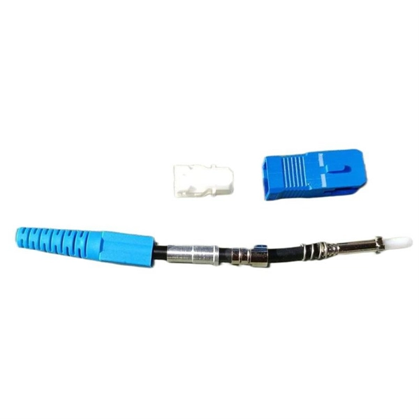
These connectors have a universal termination kit that includes all the components needed for installation. The instructions provided describe the assembly procedure for installing the connectors, including identifying the components, preparing the fiber, and assembling. FASTConnect® field-installable connectors are factory pre-polished connectors that completely eliminate the need for hand polishing in the field. Proven mechanical splice technology ensuring precision fiber alignment, a factory pre-cleaved fiber stub and a proprietary index-matching gel combine to. Comes in a pack of 6 connectors. Comparable to OCC part number FXC-ST8-6 and Corning part number 95-200-51. FAST Connectors are compatible with 250 µm and 900 µm optical fibers, as well as 4. 8 mm (SC only) cordage. A factory-installed wedge clip (included. FAST Connectors are designed for use with single-mode or multimode fiber optic cable and come in SC, ST, and LC configurations. ead these instructions carefully before proceeding. Different termination options after cleaving the fiber are provided for each fiber type ys wear eye protection.
[PDF]