Design and manage all OSP equipment from cables and conduits, to patch panels and field splitters with this fiber optic management software. Create fiber cable models using the TIA-598C color code specification, create a sub-class of OSP components with custom map icons, design custom line styles and customize data by creating new data fields. View and trace the path a cable strand takes from end to end on the map while viewing all the splice points and fiber termination points. cvFiber has simplified graphical splicing between multiple fiber cables. Users can splice buffer tube to buffer tube and strand to strand, and as well as butt splice two cables. cvFiber is seamlessly integrated with the CircuitVision cvTicket ticketing system that offers outage reporting, ticketing and bulk customer notifications.
[PDF]
Cold joints occur when there's an unintended interruption in the concrete pouring process. This results in weak seams where the two layers fail to chemically bond. Unlike construction joints, which are reinforced and planned, cold joints are structural defects that require immediate. A cold joint in concrete construction is a plane of weakness that forms when new, wet concrete is poured against concrete that has already begun to harden. They can be a real pain, potentially leading to structural issues down the line. Time to break down the details. The term "cold" is used because the two concrete layers are not bonded properly, which can result in a weakened. Few defects pose a more immediate and insidious threat to the long-term performance and intended load-transfer characteristics of a structure than cold joints in concrete columns. While often dismissed as purely aesthetic blemishes, a cold joint is, fundamentally, a failure of integration—a plane. Cold joint concrete is a common problem in the construction world. It's important for construction professionals to understand what causes cold joints and how to manage them effectively. This article takes a closer look.
[PDF]
This document describes how to use and program the Photonic Application Suite, Insertion Loss Engine. Insertion loss is measured by comparing signal power (or sound level) before and after it passes through a component or system, then expressing the difference in decibels (dB). The core process is the same across fiber optics, RF electronics, and acoustics: establish a baseline reference without. This tutorial aims to help RF engineers understand how to test and measure various RF specifications of RF power amplifiers, RF LNAs (Low-Noise Amplifiers), and RF transceivers using RF test and measurement equipment like spectrum analyzers, signal generators, and sweep oscillators. Gain is the. Coaxial cables are essential components in transmitting radio frequency (RF) signals, but they inherently attenuate these signals, a phenomenon known as cable loss or insertion loss. Yes, I would like to receive educational or promotional emails from Keysight. By clicking the button, you. Insertion loss is a critical parameter in RF engineering that refers to the loss of signal power that occurs when a component or device is inserted into a transmission line or circuit. The insertion loss measurement quantifies the effect of the resistance the cabling link offers to the transmission of the electrical signals. Insertion loss characteristics of a.
[PDF]
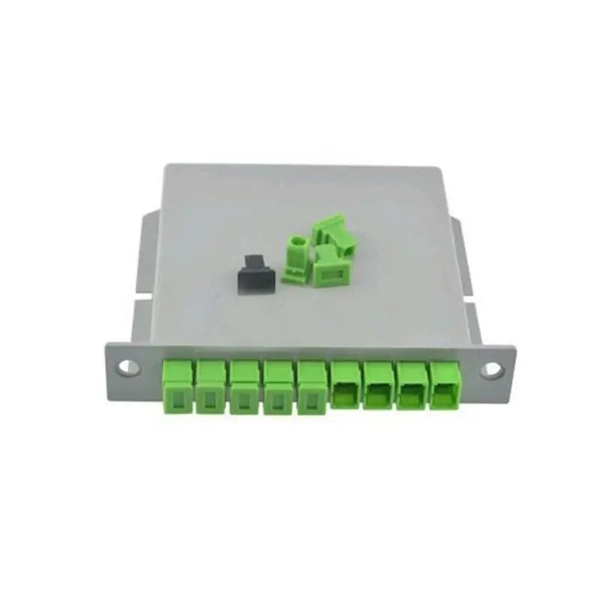
This article provides an in-depth exploration of OSFP copper cable technologies, including DAC, ACC, and AEC, with a focus on 400GB NDR splitter cable applications. Whether the signal is propagated by copper wire, optical fiber, Wi-Fi, or just yelling at the kids down the street, the signal is never as strong at the destination as it is at the source. In the case of physical voice communication, the kids will understand you if they are close-by. If they are. Insertion loss and attenuation are similar concepts, but one is assigned to a single component (insertion loss) whereas the other is assigned to generalized performance (attenuation). Both terms refer to a measurement comparing the signal strength received against a transmitted signal. Standard. Channel Master TV splitters are designed to equally divide the signals on the input port of the splitter to each of the output ports of the splitter. This. Insertion loss is the amount of energy that a signal loses as it travels along a cable link. It is a natural phenomenon that occurs for any type of transmission—whether it's electricity or data. This reduction of signal, also called attenuation, is directly related to the length of a cable—the. In fiber-optic networks like FTTx and PON, PLC splitters are key components for distributing optical signals to multiple users. However, each splitter has complex parameters, including insertion loss, return loss, polarization-dependent loss, and uniformity.
[PDF]
Mechanical splicing is a method of connecting two optical fibers without using heat or a fusion machine. Instead, it uses a small plastic or metal device to hold the fiber ends tightly together. A special index-matching gel is often used inside the splice to help light pass through the connection. You can manually splice the fiber patch cord with the help of the Procedure shown in the video. Now you can splice your patch cord. For network managers and technicians, a poor splice can lead to significant signal degradation, network downtime, and costly troubleshooting. At Turn-Key. This wikiHow article teaches the process of manually splicing patch cords and fusion splicing two fiber optic strands together in an 11-step process. The video also demonstrates how to fix a cut or. Fiber cable splicing is a critical step in building reliable fiber optic networks. Whether in data centers, telecom rooms, or outdoor FTTx deployments, proper splicing inside a fiber enclosure ensures low signal loss, long-term stability, and easy maintenance. This guide explains what fiber cable. In this guide, we cover the basics of fiber optic splicing, how to perform splicing using two different methods, and finally some best practices to perform good fiber splicing. What is Fiber Optic Splicing and Why is it Needed? – #1. Use and Maintain Your.
[PDF]