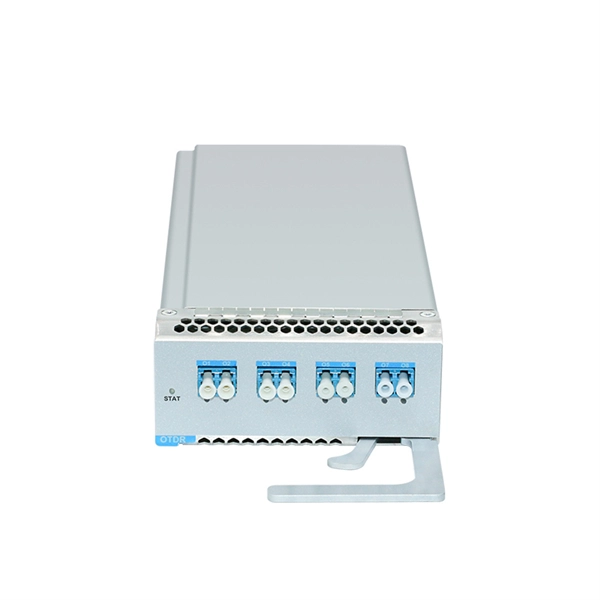
Use the command display transceiver to view the optical module information of all optical ports, and use the command display transceiver interface interface-type interface-number to view the optical module information of a specific optical port. Related Information Video Identify a Huawei-Certified Optical Module Run the display transceiver [ interface interface-type interface-number | slot slot-id ] [ verbose ]. Here is an example on how to query or display optical power of an interface in a Huawei Router. This is tested using NetEngine40E Universal Service Router or NE40E running version 8. The specific viewing information is as follows:. Optical modules are widely used in switches, network interface cards (NICs), routers, and other communication devices. During use, reading optical module information helps understand its real-time operating status, enabling faster troubleshooting of link abnormalities. Transceiver Type : 1000 _BASE_SX_SFP Connector Type :LC Wavelength(nm) : 850 Transfer Distance(m) : 300 (50 um), 150. We want to troubleshoot transceiver on Huawei router, Huawei switch, Huawei systems. 1 Show details, warning etc. from transceivers Check “Alarm information” section for warnings, LOS Alarm means no inbound signal, execute display this to check shutdown mode, execute undo shutdown if necessary.
[PDF]
Need some clarification about NEC 770. 47 (B), it says that the direct buried conductive fiber optic cable shall be 12 in (300 mm) away from the power cables. Separating high-voltage power cables from low-voltage communication cables is a fundamental requirement in any electrical installation. This practice is mandatory for two distinct reasons: ensuring the safety of the structure and its occupants, and preserving the integrity of sensitive data. Maintaining proper separation between power, data, and limited energy cabling is foundational to system performance, safety, and code compliance. Separation isn't just an EMI precaution — it protects signaling, reduces rework, and ensures pathways meet inspection expectations across risers. TECHNICAL GUIDELINE July 30, 2020 TG030 Rev. 4 Pathway Separation Between Telecommunication Cables and Power Cables Communications cables are, by design or necessity, often installed in close proximity and/or in the same pathway as power service cables. The electrical energy of the power cables can. This standard titled “Commercial Building Standard for Telecommunications Pathways and Spaces” is a joint publication of ANSI/TIA/EIA. Its current version (ANSI/TIA/EIA/-569-B) was published in October 1, 2004 and describes EMI aspects in Article 10. ca with numerous contributions by others. "UTP Separation Guidelines From EMI Sources". The values are the same as the cabling pathways standard, EIA-569, table 4.
[PDF]
Simply put, the output or transmit power (TX Power) is the strength of the signal that's leaving the device. This should fall within a specific range determined by the capabilities of the transmitter. Optical power is the degree of energy that comes from optical signals, which is one of the key parameters of a WDM system. The. In this section, we will learn how to do the following things: Determine the gain of a laser ampli er Find the threshold gain of a cavity Predict the output power of a laser Determine the output mode of the laser Unless otherwise stated, steady state ( d = 0) behavior may dt be assumed. When the signal received is outside of the range, there is a. When it comes to evaluating the performance of an optical transceiver, two key factors come to the fore: Output power (TX Power) and Receiver Sensitivity (RX Sensitivity). An understanding of these concepts is pivotal to establishing an effective and efficient optical network. This comprehensive. As an essential component of optical fiber communication, optical modules are optoelectronic devices that facilitate the conversion between optical and electrical signals during the transmission process. Transmitter power characterizes the average optical power output from the laser under rated conditions, while receiver sensitivity indicates the minimum.
[PDF]
FBT splitters are more sensitive to fiber bending and environmental expansion, particularly under uneven thermal conditions. A beam splitter or beamsplitter is an optical device that splits a beam of light into a transmitted and a reflected beam. It is a crucial part of many optical experimental and measurement systems, such as interferometers, also finding widespread application in fibre optic telecommunications. a laser beam) into two (or sometimes more) beams, which may or may not have the same optical power (radiant flux). Different types of beam splitters exist, as described in the. Fiber optic splitters distribute optical power from one input fiber to multiple output fibers through either fused biconical taper (FBT) coupling or planar lightwave circuit (PLC) waveguide structures. Their performance depends on optical symmetry, waveguide integrity, and mechanical stability of. : The invention provides a light generating system (1000) comprising a first light generating device (110), a second light generating device (120), a luminescent material (200), a diffuser assembly (700), optical elements (500) comprising a first redirection optical element (1510), and a light exit. When splitting one incident light beam into two separate beams, beamsplitters are applied. Depending on the beam split based on intensity, wavelength, or polarization, its level of optical power on beam penetration differ. Just to mention few, these beamsplitter components are commonly required for.
[PDF]
An optical power meter is an electronic device that measures the power of an optical signal. It helps engineers verify the performance of optical fiber systems, ensuring that the signal strength meets requirements, and is an essential tool for communication network maintenance and. An optical power meter (OPM) is a device used to measure the power in an optical signal. Other general purpose light power measuring devices are usually called radiometers, photometers, laser power meters (can be. An optical power meter (OPM) measures the power levels of light signals in devices that transmit data or power using light. The term "optical power meter" may sound generic, but in popular usage, it specifically implies a fiber optic power meter. For light power measurements outside the field of. Optical Power Meters (OPMs) are crucial instruments in the field of optical sensors and fiber optic communications. It provides an expert-curated supplier directory, buyer-focused technical background information, and structured selection criteria to support professional procurement decisions. It measures optical power directly, and it is also used in loss testing when paired with a stable light source.
[PDF]
Use this selector tool to quickly identify the best power supply for your aerospace and defense ATE requirements. Explore engineer-authored content and a vast knowledge base with thousands of learning opportunities. Use 25+ X-Series applications to analyze, demodulate, and troubleshoot signals across wireless, aerospace/defense, EMI, and phase noise. With extra memory and storage, these enhanced NPBs run Keysight's AI security and performance monitoring software and AI stack. Achieve fast, accurate board-level. Fiber-optic switches control light paths within fiber optics, ranging from simple on/off types to complex matrix configurations like 64×64. Fiber-optic switches are optical switches in the context of fiber optics. They're a core component in fiber-optic networks, where data travels as pulses of light through glass fibers. This technology allows for high bit rate transmission to be switched between various optical lines. All of these optical switches are purely optical path, there is no optical to electrical to optical conversion. Click to jump to class of switch --- Provides a bypass of.
[PDF]
This comprehensive guide breaks down the internal structure, core components (TOSA, ROSA, lasers), and operational mechanisms of SFP optical modules, enriched with technical insights and real-world applications. As an essential component of optical fiber communication, optical modules are optoelectronic devices that facilitate the conversion between optical and electrical signals during the transmission process. Optical Modules (also known as Optical Transceivers) are critical components in fiber optic communication systems. This assembly comprises a light source, such as a laser diode or a semiconductor light-emitting diode (LED), an optical interface, a. Whether you're selecting an optical transceiver module for short-range multimode applications or long-haul coherent transmission, understanding these parameters ensures reliability and performance. We'll cover everything from physical form factors to spectral characteristics, modulation formats.
[PDF]
A WDM system uses a multiplexer at the transmitter to join the several signals together and a demultiplexer at the receiver to split them apart. With the right type of fiber, it is possible to have a device that does both simultaneously and can function as an optical add-drop. In fiber-optic communications, wavelength-division multiplexing (WDM) is a technology which multiplexes a number of optical carrier signals onto a single optical fiber by using different wavelengths (i., colors) of laser light. This technique enables bidirectional communications over a. WDM is a fiber optic transmission technique that leverages multiple light wavelengths to transmit data efficiently over a single medium. WDM technology employs different optical wavelengths, or colors, of laser light to multiplex several optical carrier signals onto a solitary optical fiber. Each. There are a lot of people who don't understand the difference between WDM and optical splitter. This allows multiple channels of data to be transmitted simultaneously. WDM technologies allow organizations to place equipment at either end of a fiber pair and combine multiple wavelength channels on a single fiber pair instead of using multiple separate fibers pairs for every separate service. The article explains the fundamental principle and its.
[PDF]
Are you purchasing a new router or upgrading an old one? Use this tool to find the router that fits your needs. Juniper's single-box Packet Optical convergence solutions help operators simplify operations, lower transport costs, and tap new revenue opportunities. The ACX5400 Series of 1U routers provide power-efficient metro aggregation and support full IP/MPLS functionality. They deliver the performance. AI readiness comprises six pillars: Strategy, Infrastructure, Data, Governance, Talent, and Culture. Is your organization AI ready? Build the bridge between business outcomes and technology with our new interactive tool. Provide outsourced IT and consulting services with a broad technology. Whether you're upgrading enterprise Wi-Fi or need a high-performance enterprise wireless router, finding the right fit is essential. At Meter, we know how important it is to choose a router that delivers on performance, security, and scalability. That's why we've curated this guide to the best. The Huawei FTTR-SME OptiXstar B50 can function an intelligent optical network hub for SMEs by providing converged network, cloud, security, video, and computing services. It can be used to build secure, reliable, ultra-high bandwidth, and ultra-high concurrency all-optical Wi-Fi networks for SMEs. For SMBs, enterprise routers offer. Milesight helps customers in buildings, retail, healthcare, education, and more achieve their goals smarter and faster. Explore Milesight's.
[PDF]
To set up your router for fiber internet quickly, connect the router to your fiber modem, access the router's settings via a web browser, and input the provided ISP credentials. Make sure to update the firmware, configure Wi-Fi security, and customize your network name for. However, setting up a fiber optic connection to your router can seem daunting if you're unfamiliar with the process. In this guide, we'll walk you through how to connect a fiber optic cable to a router safely and efficiently. Why Use Fiber Optic Internet? Before diving into the setup, let's quickly. Setting up a fiber internet connection requires understanding key hardware components and following a specific connection sequence to establish your home network. The fiber. The process to connect fiber optic cable to router requires careful attention to detail, but I'll walk you through every critical step with the precision and clarity you deserve. Here's a step-by-step guide to help you through it. Check compatibility: Before you begin, make sure your router supports fiber optic connection. Our Experts are helping user's, who are facing issues with their tech gadgets like Router, Modem and extender.
[PDF]
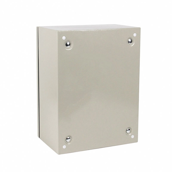
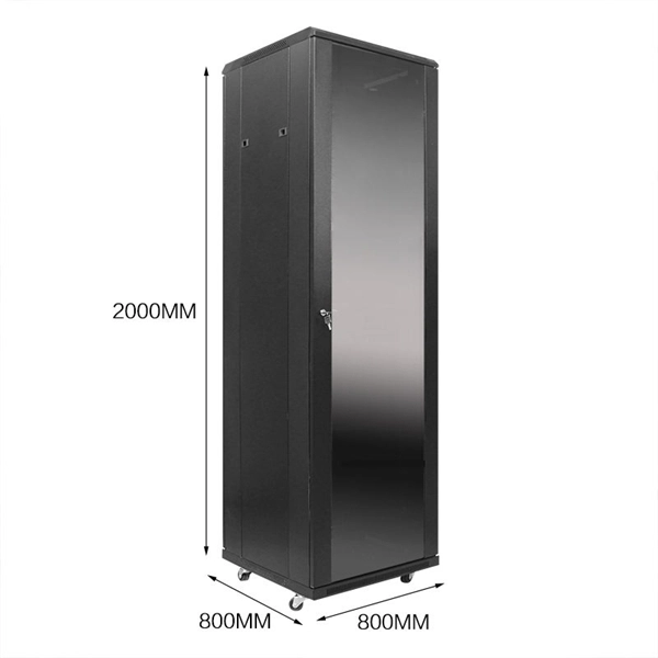
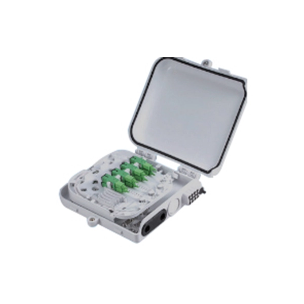
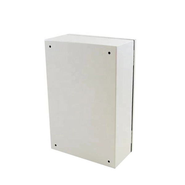
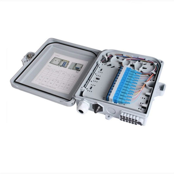
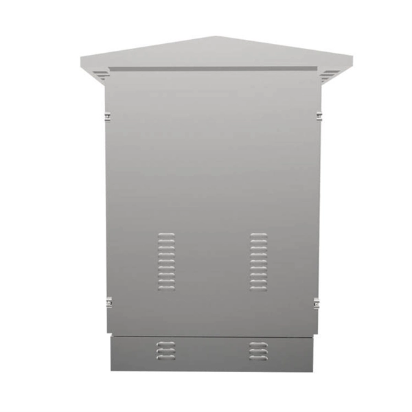
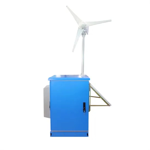
Through the adapter in the distribution box, the optical signal is led out by the optical jumper to realize the optical wiring function. An optical cable consists of three primary parts: the core, the cladding, and the protective sheath. The core is at the center of the optical cable and serves as the pathway for transmitting light signals. Surrounding the core is the cladding, which has a lower refractive index than the core. In the complex architecture of fiber optic networks, the Optical Distribution Frame (ODF) serves as the linchpin for organizing, protecting, and distributing optical signals. Whether in data centers, telecom central offices, or enterprise network rooms, ODFs enable efficient fiber management. The optical fiber distribution box is to protect the connection point where the optical cable is connected to the user end, so that the optical cable access point is stable, dustproof and waterproof. What is a fiber distribution box? 2. The. A fiber distribution box (FDB) functions as a central hub in fiber optic networks where the main cable is split into multiple individual fibers for distribution to end users. These boxes protect sensitive fiber connections from environmental factors while providing an organized framework for.
[PDF]
Locate Fiber Optic Cables suppliers, manufacturers & distributors in Sweden. Interactive map of Sweden provided. Nexans' range of fiber optic cables includes products intended for data and telecommunications as well as industrial applications. Robust cables for national networks, city networks, rural networks and property networks, for installation indoors, outdoors, in ground pipes, in air systems and in. The Swedish Microwave fiber cables are made as ruggedized cables with narrow bend radius and very good performance to fit together with all our RF over Fiber products. They are all single-mode fiber cables and IP 65 classed when mated. Their product range includes robust cables suitable for various environments, ensuring exceptional performance and fire. Eurolan Uni LT fiber cables are used in backbone, distribution networks or in FTTH solutions. Can be laid indoors as it is or outdoors in pipes. 8 mm gel filled loose tube with 2 - 12 fibers; ø 3. Eurolan LT fiber cables are used in backbone. Air Blown Cables are super slim fiber optic cables to be blown into microducts. Ideal for telecommunications, data centres and networking applications, our fibre optic cables are available in single-mode and multimode configurations.
[PDF]
Optical isolators protect sensitive sources by blocking back-reflected light that could cause instability or damage. Optical circulators, meanwhile, manage directional routing through multiple ports, enabling duplex communication, optical path control, and compact system. of low-loss non-reciprocal fiber-based devices. Here, we present a solution to this issue by realizing low-loss (0. 81 dB), broadband (at least 50 GHz bandwidth) and high-extinction (up to 27 dB) circulators, based on Mach-Zehnder interfer meters including so-called fiber null-couplers. The latter. The ABSTRACT optical circulator is one of the key devices in the optical add-drop modules (OADMs) used in wavelength-division multiplexing (WDM) technology, which finds applications in large-capacity long-haul telecommunications systems. PM circulators. Faraday circulators (or less specifically optical circulators) are a kind of non-reciprocal optical devices. They are technically related to Faraday isolators, and on a broader scale similar to electronic circulators. Typically, a circulator has three or four optical ports (inputs / outputs). GKER Photonics Co. is really leading the charge in this area, providing key Optical Components that boost the reliability and performance of things like industrial fiber lasers and optical networks, not to mention data centers. If global suppliers take the time to understand what really.
[PDF]
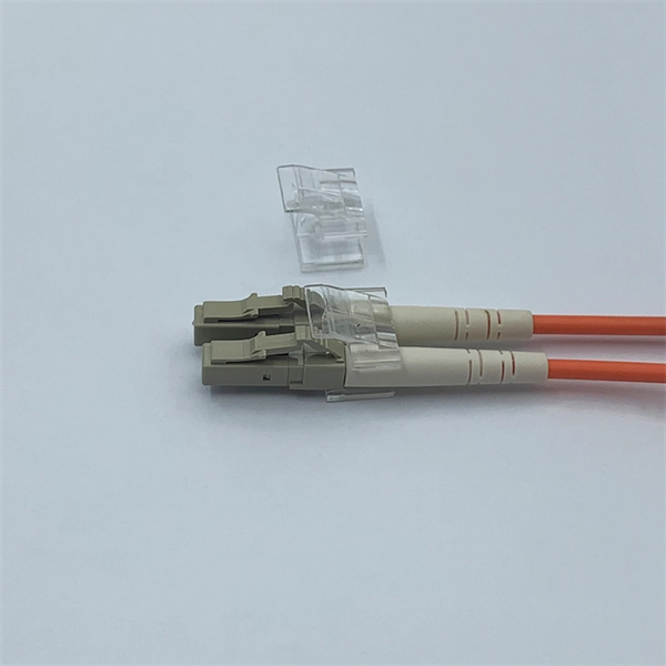
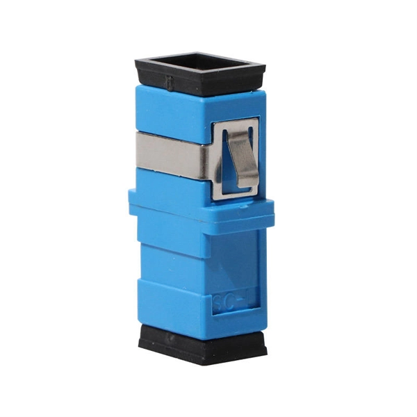
The simplest method: connect two cables pre-connectorized via a coupler (also called an adapter). The coupler aligns the two ferrules of the connectors using a zirconia sleeve. Why connect two fibers? Do you need to extend, repair, or connect two fiber optic cables? There are three methods main ones, each with its advantages and limitations. This article explains when. Optical fiber fast connectors, also known as cold connectors, are becoming increasingly popular due to their ease of use and quick installation. Unlike traditional fiber connectors that require epoxy and polishing, fast connectors use a mechanical splice to join the fibers. Another method is using a mechanical splice which involves aligning and securing the fiber ends with a precision. Fiber optic cables can be connected together using a couple of different methods: 1. This creates a permanent and low-loss connection. Connectors play a crucial role in our daily lives, yet there are some connectors that remain less familiar, such as fiber optic fast connectors. The goal is clean.
[PDF]
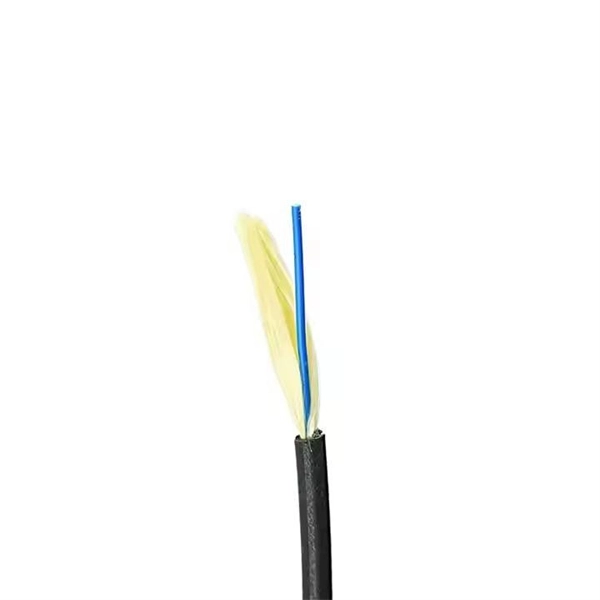
Optical fiber consists of a and a layer, selected for due to the difference in the between the two. In practical fibers, the cladding is usually coated with a layer of or. This coating protects the fiber from damage but does not contribute to its properties. Individual coated fibers (or fibers formed into ribbons or bundles) then ha.
[PDF]