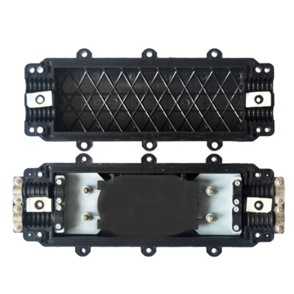
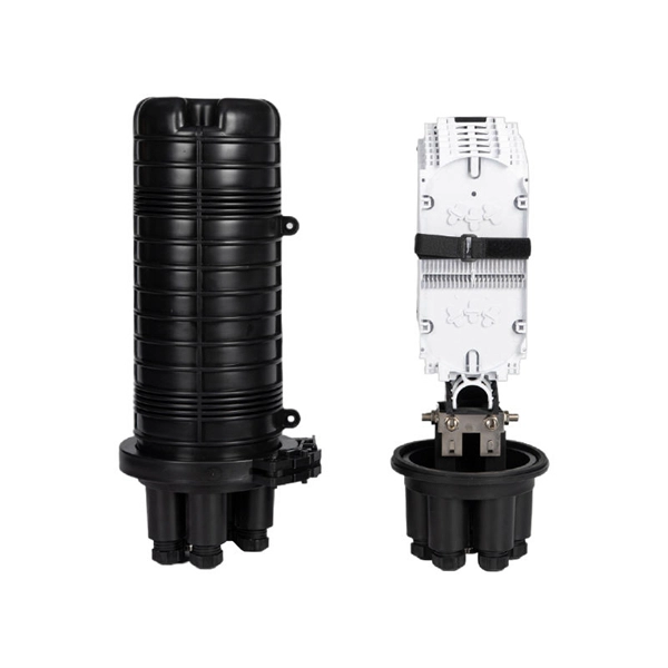
The medium sized closure shall accommodate up to 288 single fiber splices or 432 ribbon fiber splices. Buffer tubes shall not be subjected to a bend radius smaller. For protection against the outside plant environment and damage, splices require placement in a protective enclosure, usually called a splice closure. Splices are generally placed in a splice tray which is then placed inside a splice closure or integrated into a fiber pedestal for OSP. 2. Although a compact size, there is ample room to express 144 fiber cable. The FSDC series closures are fully sealed units which can be mounted on a. Fiber Splice Tray in Fiber Optic Splice Closure The fiber optic splice closure is component which is widely used in today's fiber optic network for outdoor applications and harsh environment. Fiber splice closures are not used occasionally — they are deployed extensively across every fiber network. The exact quantity depends on population density, network topology, and regional infrastructure planning. Below is a simplified example based on a 10 km coverage area serving approximately. Amphenol fiber optic sealed drop closures provide a versatile and functional cost-effective solution for FTTH network connections to the subscriber.
[PDF]
In this guide, we'll walk you through the entire process of preparing fiber optic cable for splicing and termination to fiber connectors. We'll explore the necessary tools, safety precautions, and step-by-step procedures for cable connectors, mechanical and fusion. Think of a fiber optic cable splice as the seamless stitching that keeps data flowing through the delicate threads of a network—like a master tailor joining fabric with precision. Whether repairing a broken cable or extending a fiber run, fiber optic splicing ensures light signals travel. Splicing fiber optic cable is an extremely important phase for making dependable, high-speed communication infrastructures. Regardless of the type of fiber network you're deploying, be it for telecom, enterprise data centers, or smart city infrastructure, fusion splicing provides the benefits of. This guide reveals the secrets to fusion splicing with little fluff—just proven, straightforward techniques refined from years of work in the field. The guide provides the complete workflow, covering safety precautions, tool selection, fiber preparation, fusion operation, quality control, and. Executive Summary: A fiber optic pigtail is one of the most commonly specified yet least understood components in structured cabling. What is Fiber Optic Splicing and Why is it Needed? – #1.
[PDF]
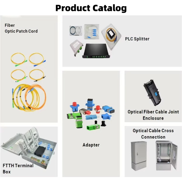
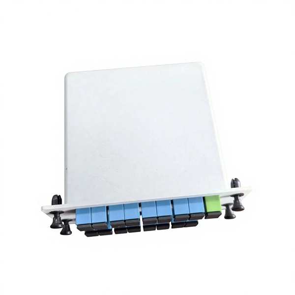
A splice box (also known as splice distributor) is a housing in which fiber optic cables begin or end. Fiber optics are fanned out in splice boxes that are situated at the end of fiber optic transmission paths. It typically consists of two parts: an outer housing and an internal structure. The main components of a splice box are the splice cassette that picks up the fibers and. The fiber optic dome splice closure is well-suited for splicing, distributing variable optical cables, and splitting. The solid box shell and the main structure are built to withstand harsh environments. The dome closure also protects fiber optic cables from vibration, impact, stretching, twisting. Home » Professional Insights » Fiber Optic Splice Closure: A Complete Guide to Types, Structure, Applications, and Selection In real fiber optic networks, cables are rarely installed as one continuous, uninterrupted length. Along transmission routes—whether in access networks, metro networks, or. Big space for managing pigtails or splitters. The 12 Port Fiber Distribution Box can connect up to 2 optical cables, providing space for distributors and 12 fuses. It is equipped with 12 SC adapters and can work in outdoor environments. Data communication networks. Horizontal fiber optic splice closures, also known as optical cable splice boxes, play an important role in the communications industry. It is a must-have device in the construction of optical cable line projects.
[PDF]
Fiber optic splicing metal box for 8 adaptors SC simplex, LC duplex or E2000. Wall mounting enabled. All products' documentation is published in PDF (Portable Document Format), which requires Adobe Reader (ver. 5 and newer) software for viewing. Though we pay utmost attention, we cannot guarantee. Every payment you make on Alibaba. com is secured with strict SSL encryption and PCI DSS data protection protocols Claim a refund if your order doesn't ship, is missing, or arrives with product issues. The HAILE 8 Optical Fiber Termination Box P1-8-FC is an essential fiber optic distribution frame designed to manage and protect fiber optic cables in various networking environments. This termination box is equipped with 8 ports that support FC connectors, making it ideal for high-performance. Fiberlink provides fiber optic splice box products for FTTH solution, including fiber terminal box, fiber splice enclosure, optical distribution box. FBR-11607 Fiber-Optic Distribution Box, 8-Core is a high quality product by Bud Industries used for electronic enclosure applications.
[PDF]
Fiber splice closures are not used occasionally — they are deployed extensively across every fiber network. The exact quantity depends on population density, network topology, and regional infrastructure planning. There are hundreds of different designs and options on splice closures. Some are designed for concatenation of long distance cables where two identical cables are spliced together. Its role is not only to enclose the splice, but to ensure that optical performance remains stable throughout years of operation. In FTTX and outdoor access networks especially, the reliability of. There are several types of fiber optic splice closures available in the market, each designed for specific applications and environments. There are many possible ways to put two or more cables together or drop a single fiber at a location. It creates an air-tight environment that safeguards these splices from environmental considerations, including wetness, dust, and temperature changes; hence, the. CommScope addresses these challenges with a comprehensive family of fiber splice closures that prioritize essential criteria: reliability, installability, flexibility, and speed of deployment. Trunk and Feeder Network Solutions: These closures are designed for robust performance in the backbone of.
[PDF]
The core principle of fiber optic splicing is to achieve low-loss, high-strength junctions between fiber ends. This involves three key steps: preparation, alignment, and bonding. Let's break it down technically:. At the core of this system's precision and reliability are Fiber Optic Splice Boxes—the unsung heroes that house and protect the delicate junctions where fiber cables are joined. The integrity of these enclosures is paramount to network performance. This guide optimizes the original text by delving. A splice box (also known as splice distributor) is a housing in which fiber optic cables begin or end. Key Functions Typical Applications ZION FTB Highlights In essence: The Fiber Terminal Box is an end-user termination device for small-scale distribution. ■ What Is a Fiber. Fiber optic cables are the lifeline of modern telecommunications, delivering high-speed data with minimal loss. However, installing and maintaining these networks requires seamless connections between fiber segments—a process known as fiber optic splicing. Understanding how it works is essential for anyone interested in telecommunications or network infrastructure. Essential for mending faults or scaling networks, splicing underpins the backbone of contemporary communications. In this comprehensive guide.
[PDF]
There are temporary splices that use a sleeve and index matching jell but they are expensive and if you don't prepare the fibre ends properly they won't work anyway. The correct fix will probably be a Field Tech with a fusion splicer and cleaver which is thousands of dollars worth. The most detailed cold splicing prodcedures for broken fiber optic cable. You can source the fiber optic cables or other cabling products from the manufacturer supplier at factory prices on site: https://www. more The most detailed cold splicing prodcedures for broken. Fiber optic joints or terminations are made two ways: 1) splices which create a permanent joint between the two fibers or 2) connectors that mate two fibers to create a temporary joint and/or connect the fiber to a piece of network gear. Either joining method must have three primary characteristics. Before splicing or connecting, clean the stripped and cleaved fiber ends using alcohol and lint-free wipes to remove dust, oil, or other contaminants. Clean fiber ends ensure low-loss, reliable connections. For network managers and technicians, a poor splice can lead to significant signal degradation, network downtime, and costly troubleshooting. At Turn-Key. Whether you are building a new backbone, restoring service after damage, or upgrading an existing route, disciplined fiber optic splicing techniques determine signal integrity, longevity, and operational uptime. These terminations must be of the right style, installed in a.
[PDF]
OPGW cable joint box installation involves several key stages: selecting the appropriate location, preparing both the cable and the joint box, splicing fibers, and sealing the joint box properly. Adhering to these steps ensures optimal performance and longevity of the telecommunications system. Optical fiber junction boxes are essential components in outdoor optical fiber cable installations. In this article, we will discuss the necessary steps and best practices. The Indoor/Outdoor Splice Box is a wall-mounted, indoor/outdoor fiber splice enclosure for centralized splice-only applications. These boxes are well suited as optical cable splice collection points for MDU (Multi-Dwelling Unit) residential fiber network applications, MTU (Multi-Tenant Unit). The installation of an optical cable junction box is crucial in ensuring the integrity and performance of optical networks. As we enter 2024, adhering to best practices not only enhances system reliability but also mitigates potential issues that can affect customer experiences. Installing a fiber optic splice closure efficiently and effectively requires attention to detail and. AFL's SB01 splice enclosure provides protection from all types of elements. From weather to bullets, the iron and steel construction requires no additional protective covering. Furnished with four plugged cable ports (2 aluminum and 2 plastic) for either All-Dielectric Self-Supporting (ADSS) or.
[PDF]
Optical fibre has been installed along 1,600 kilometres length so far under the Optical Fibre Backbone Network Expansion Project across the country. Hording board used for barricading should be prop rly fastened to the ground. Further, to allow movement of commuters, backfilling shall be done as soon as necessary length of pipe are laid in trench for easy and quic completion of the Project. The Contractor shall be. o the Home (FTTH) Infrastructure (September isaster Warning: Opportunities and Legal Challenges (ITU, 2012). Available line for sustainable transport in Asia-Pacific, 6 Dec er nce with support from government authorities and market players. The planning for setting up the infrastructure should. As per the agreement, an extension of optical fibers would complete in two years. So far, the optical fibers have been laid on 1,006-km (46.
[PDF]
Each drop wheel is spooled with 200 feet (60. 96 m) of FieldShield StrongFiber, pre-terminated with a pullable SC/APC or SC/UPC connector. The drop wheel is easily deployed by extending the wheel from the cradle and pulling the fiber through the microduct or conduit. This placement wheel can easily be attached and loaded in seconds. With a Minimum Bend Diameter of 12”, the Hi-Roller accommodates most aerial communications cables used today. Lightweight and capable of handling loads not to exceed 1000 lbs., (Fiber Optic Cable recommended load rating is 600LBF). le in a variety of sizes. With more than one million units in service, Opti-Loop fiber storage systems lead the industry cable up to 1. They provide a convenient, economically priced and industry approved method of storing extra le e stacked if necessary s for storing. This Block is normally used for pulling in self support or prelashed cable and is mounted with either a B, C, D, E, or F Cable Block Frame at a pole. Cable Block Frames are used to support either the E Cable Block (GMP74055) or Self Support Cable Block (GMP70200) when pulling in prelashed or self. The aluminum Opti-Loop™ FOS for strand and messenger mounted cable is available in a variety of sizes.
[PDF]
The OSFP footprint is optimized for signal integrity performance and built for use in high-speed serial applications. The connectors are enhanced for low crosstalk and have ground commoning for resonance dampening. They are also designed for 1U applications. TE's Octal Small Form Factor Pluggable (OSFP) connectors and cable assemblies support aggregate data rates from 200 Gbps up to 1. 6T, enabling data center architectures to scale with evolving bandwidth and performance requirements. Designed to support 28G NRZ, 56G PAM4, 112G PAM4, and 224G PAM4. This specification defines the electrical connectors, electrical signals and power supplies, mechanical and thermal requirements of the OSFP Module, connector and cage systems. The OSFP Management interface is described in a separate document, Common Management Interface Specification for 8/16X. The Octal Small Form Factor Pluggable (OSFP) Connector System provides up to 224Gbps PAM-4 per lane, single- or dual-port, 8- or 16-lane connectivity. These products are designed for both 28G NRZ and 56G PAM-4 protocols, with a roadmap. Q: What is the difference between NRZ and PAM-4 signaling in OSFP connectors? OSFP (Octal Small Form-factor Pluggable) is the high-density, hot-pluggable connector for 400G and 800G Ethernet. It uses 8 lanes at 50G PAM4 (400G) or 100G PAM4 (800G) with a 60-pin edge connector. TE Connectivity's OSFP.
[PDF]
This AutoCAD DWG file includes a complete MDB single line diagram showing circuit breakers, feeders, incomer, metering, and outgoing distribution arrangement. This technical article describes single line diagrams of two typical power substations 66/11 kV and 11/0. 4 kV and their power flow, principles of incoming lines (incomers) and outgoing lines (feeders), busbar arrangement functionality and so on. Regarding elements in single-line diagrams, they were. Check electrical parameters: First understand the basic electrical parameters of Distribution box so that you can have a general understanding of the capacity and performance of the distribution box. The Key Diagram of Substation can be explained as under: 1. There are two 66 kV incoming lines marked 'incoming 1' and 'incoming 2' connected to the bus-bars. An electrical substation is a subsidiary station of an electricity generation, transmission and distribution system where voltage is transformed from high to low or the reverse using transformers. Electric power may flow through several substations between generating plant and consumer, and may be.
[PDF]
The Jassar Qubical Box FWF 10 Way is a sturdy and reliable electrical distribution box, ideal for residential and commercial use in Kuwait. With its compact design and 10-way configuration, it provides a convenient and space-saving solution for managing electrical. Distribution box,ezitown distribution cabinets, sub power distribution cabinet,distribution board and lighting distribution cabinet (box), metering cabinet (box), is the last stage equipment distribution system. Ezitown Distribution cabinet is collectively motor control centers. Distribution. Electrical cables, accessories, Lighting fixtures, Conduit pipes & fittings, Cable trays & cable support systems, Circuit breakers, switch boards & panels, Water proof junction boxes, Electrical switches, Plugs & adaptors cable, Fuses, Explosion proof lamps, Electrical crimping tools, Pliers. Top quality electrical products available at cheap and best price in Kuwait. Our commitment to excellence has enabled us to establish enduring relationships with leading manufacturers across the globe. With our team of highly trained personnel, we provide. We provide an extensive range of type-tested distribution boards for low-voltage (LV) electrical systems that are suitable for residential, commercial, and industrial properties. Each unit is manufactured in accordance with IEC standards and tested in state-of-the-art laboratories to ensure.
[PDF]
On average, a single fusion splice can take anywhere from 10 to 30 minutes, including preparation and testing. The answer isn't always straightforward, as it depends on various factors, including the type of fiber, the splicing method, and the level of expertise of the technician. Before we dive into the timeline, it's essential to understand the splicing process itself. Fiber splicing involves several. Fusion splicing refers to a method of joining two optic fibers together by means of heat, often an electric arc, which fuses the glass ends. It is the technique that has the least insertion loss and almost no back reflection, hence ensuring strong connections over a long period. A welding machine. This is typically done when the cable length is insufficient or when the fiber network is damaged and needs restoration. Unlike connectors, which are used for temporary joints, splicing creates a permanent, low-loss connection. This process is essential in telecommunications for extending network reach or repairing damaged sections without replacing entire cables. Splicing preserves the integrity and efficiency of the fiber optic network, offering a cost-effective solution for. A chart developed by Fiber Optic Association master instructor Joe Botha helps technicians calculate the amount of time it will take to conduct a fusion-splcing project. The FOA mentioned the chart in its November 2011 newsletter, stating, "We've been asked many times, 'How long does it take to.
[PDF]
Picking up the best router for fiber internet isn't just about going to the market and choosing one of the best wireless routers. Instead, you need to carefully look at its specs, performance, and the type of securit.
[PDF]