Yes, you can connect two routers to one fiber modem, but understanding the 'how' and 'why' is crucial for optimal network performance. This guide clarifies the possibilities, practical methods, and potential pitfalls, ensuring you maximize your home or small office network. There's no magic number as to how many devices fiber internet can support. Your speed, the size of your home, your router and your level of connectivity will all factor in to how well your devices perform. How many devices you have The average home has over 20 online devices. You probably. One common question arises: Can you have two routers with AT&T Fiber? The short answer is yes, but it comes with nuances. AT&T's service requires their proprietary gateway (a modem-router combo), but you can add a second router—your own—for enhanced features like wider WiFi range or advanced. Every router has a limit to the number of devices it can efficiently support at once. The maximum device capacity varies depending on the router's hardware specifications, Wi-Fi® standards, and intended use case. Can I Connect Two. Routers are designed to handle a certain number of devices, but the exact capacity varies depending on the type and quality of the router. Useful settings: separate bands, prioritize traffic, wire fixed lines, and limit clients. With 15-20 WiFi clients.
[PDF]
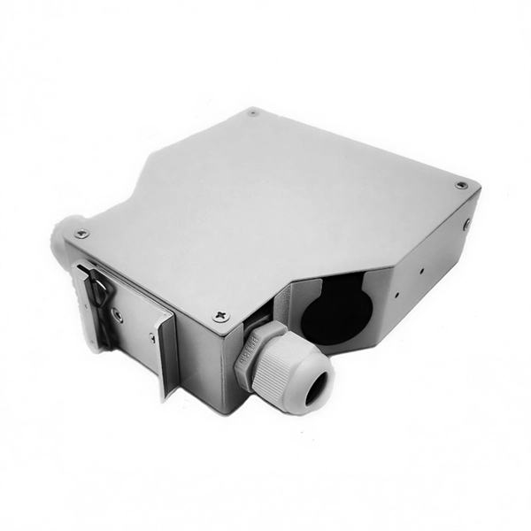
While there are situations when you will have to route cable through structural members such as studs, joists, and rafters, the job is much easier if you can run the cable along the surfaces of these frames. When you have a situation where you need to run cable through. Running new wiring within existing, finished walls of a wood-framed structure is a common necessity for home upgrades, whether for installing low-voltage data and audio cables or for extending line-voltage electrical circuits. Another is to conceal the cords and cables within the walls. This guide will help you learn how to run low voltage cables through the wall using low voltage boxes and face plates. To learn how to add. Many home improvement projects require you to install new electrical cables inside finished walls. The process is often called "snaking" or "fishing," with good reason. Cables often must be bent, slithered and coaxed around stud spaces and through small holes in the framing. Click on any image to see a larger version. When installing an electrical box, drill a hole in the floor between the studs on the same side as the electrical box. Staple down the wire right above the hole and. Method One: In order to cut the panel correctly, you first need to make the right measurements. Mark this distance on the panel you will be using. Make sure to mark this from the top.
[PDF]
Cable tray support quantity can be calculated using a simple formula: Support Quantity = Total Length ÷ Support Spacing + 1 20 ÷ 2 + 1 = 11 supports In a typical project, a 20-meter cable tray with 2-meter spacing requires 11 supports. This article explains the principles, methods, and practical examples for calculating cable tray support quantity. Select Fill Standard: Choose 40% for power cables (NEC compliant) or 50% for. The right cable tray sizing calculator helps engineers turn cable schedules into a verified tray width and fill check before material ordering and site installation. For licensed electricians, mastering these principles is essential. Maximum allowable tray fill per Area (in^2) Tray Design Depth = Sum of OD (in) Total Cross Sectional Areas of all cables: Total Sum of the Diameters: in. Per NEC Tray Sizing Instructions 1) Insure that macros have been enabled. 9 (B), when using ventilated tray with multi conductor control cable, the sum of the cross sectional areas shall not exceed 50 percent of the interior cross section of the cable raceway / tray.
[PDF]
8032 is the gold standard for implementing ring networking topographies. When implemented properly, G. 8032 management safeguards Ethernet traffic and achieves recovery times of less than 50 milliseconds (ms). This document provides basic background information regarding adding ring redundancy in your wired Ethernet networks. It will explore the N-Tron proprietary protocol N-Ring and how it is a step up from IEEE Spanning Tree and Rapid Spanning Tree Protocol (STP, RSTP). Examples for creating a. Ethernet Ring Protection Switching (ERPS) is an effort at ITU-T under G. 8032 Recommendation to provide sub-50ms protection and recovery switching for Ethernet traffic in a ring topology and at the same time ensuring that there are no loops formed at the Ethernet layer. This ITU-T specification is. Device Level Ring (DLR) is a Layer 2 protocol that enables redundancy in a ring topology, providing fast network fault detection and reconfiguration for industrial networks. DLR is an EtherNet/IP™ protocol that is defined by the Open DeviceNet® Vendors' Association (ODVA). 8032 management safeguards. The ITU-T G. ERPS is similar to spanning-tree protocols, but ERPS is more efficient because it is customized for ring topologies.
[PDF]
Wireless Capabilities: It supports 802. 11an+ac protocols for 5GHz and 802. 4GHz, with a 2x2:2 MIMO configuration for both bands 2. 4GHz, categorizing it as an AC1200 class device 2. NOTE: During configuration or flashing a device, the only things that should be hooked to the device is the computer and power. This device is NOT RECOMMENDED for future use with OpenWrt due to low flash/ram. DO NOT BUY DEVICES WITH 8MB FLASH / 64MB RAM if you intend to flash an up-to-date and. Hardware Details: The Phicomm K2P (A1) is a wireless router released around June 2017, manufactured in China 2. It features a MediaTek MT7621AT CPU (880 MHz, 2 cores), 16 MiB of flash memory, and 128 MiB of RAM 2. 11bgn for. Over the past year, the Phicomm K2 (model PSG1218) has become one of the most frequently discussed legacy routers in DIY networking communities—not because it's new, but because its hardware remains unusually capable for its price point, especially after flashing OpenWrt 1. 4 GHz and 5 GHz radios. It has five Fast Ethernet ports, later revisions featuring five Gigabit Ethernet ports, and a moderately fast processor. This device does not have sufficient resources (flash and/or RAM) to. To find the best router for fiber internet, we used our expertise to select items based on key specs, such as speeds, coverage, wireless standards, security, weight, and additional features. We conduct in-house testing to check their signal strength, speed, and file transfer speed.
[PDF]
At Superfab Cable Trays, quality is the cornerstone of our operations. We meticulously manufacture our cable and support systems using only premium, high-grade raw materials that rigorously adhere to international standards and best practices. Looking for a trusted source to buy Cable Tray In Belarus? Brilltech Engineers Pvt. Ltd is the one you can reach. We have a highly experienced team, well-loaded manufacturing unit and a lot more to match up the ever-evolving needs of our customers. Moreover, our focus on maintaining high quality. Keep your cables safe and organized with our high-quality cable trays. Cable Trays are important for ensuring the protection of the wiring system and supporting insulated electric cables used for distribution and communication. Ltd is one of the trusted Cable Tray. Cable Support Systems are well designed to provide necessary support for cable trays, cable ladders and trunkings. Cable supports are manufactured according to common standards from high quality raw materials. Being one of the leading Cable. The Carpel cable carrying raceway is made from galvanized steel with a thickness of 1. The inertia moment is 1. 5mm. Europe is home to some of the world's most trusted cable tray manufacturers, known for their advanced designs, high-quality standards, and adherence to rigorous compliance standards. The European market focuses heavily on sustainability, product longevity, and easy installation, making it a.
[PDF]
A beam splitter or beamsplitter is an optical device that splits a beam of light into a transmitted and a reflected beam. It is a crucial part of many optical experimental and measurement systems, such as interferometers, also finding widespread application in fibre optic telecommunications. DesignsIn its most common form, a cube, a beam splitter is made from two triangular glass which are glued together at their base using polyester,, or urethane-based adhesives. (Before these synthetic,. Beam splitters are sometimes used to recombine beams of light, as in a. In this case there are two incoming beams, and potentially two outgoing beams. But the amplitudes. For beam splitters with two incoming beams, using a classical, lossless beam splitter with Ea and Eb each incident at one of the inputs, the two output fields Ec and Ed are linearly related to the inputs thro.
[PDF]
Typically made of glass, a beam splitter divides the light passing through it at a ratio. Usually, half of the light is reflected at an angle, and the other half is transmitted to the opposite side of the light source. A beam splitter or beamsplitter is an optical device that splits a beam of light into a transmitted and a reflected beam. It is a crucial part of many optical experimental and measurement systems, such as interferometers, also finding widespread application in fibre optic telecommunications. This division allows for the simultaneous analysis or utilization of the light's properties along two separate paths. a laser beam) into two (or sometimes more) beams, which may or may not have the same optical power (radiant flux).
[PDF]
The AOI impacts the amount of light being reflected and transmitted. For example, most plate beam splitters have an AOI of 45 degrees, which may limit those who need more flexibility. A beam splitter or beamsplitter is an optical device that splits a beam of light into a transmitted and a reflected beam. It is a crucial part of many optical experimental and measurement systems, such as interferometers, also finding widespread application in fibre optic telecommunications. a laser beam) into two (or sometimes more) beams, which may or may not have the same optical power (radiant flux). Their precision and versatility make them indispensable in a variety of scientific, industrial, and technological applications. Beamsplitters are often classified according to their construction: cube or plate. Beamsplitters are fundamental components in optical engineering, serving to precisely divide a single input beam of light into two distinct output beams. This division allows for the simultaneous analysis or utilization of the light's properties along two separate paths. The device is purely. The beam splitter splits and then recombines infrared radiation, while the detector picks up the resulting signal. It's sensitive to both intensity and frequency. Together, they decide just how accurately an instrument captures those unique infrared “fingerprints” from different substances.
[PDF]
Long-pass dichroic beam splitters are designed to transmit longer wavelengths of light and reflect shorter wavelengths, while short-pass dichroic beam splitters do the opposite. While this type of beam splitter is less common, it can be useful for fluorescent applications, such as. A beam splitter or beamsplitter is an optical device that splits a beam of light into a transmitted and a reflected beam. It is a crucial part of many optical experimental and measurement systems, such as interferometers, also finding widespread application in fibre optic telecommunications. In its. Beamsplitters are optical components used to split incident light at a designated ratio into two separate beams. Additionally, beamsplitters can be used in reverse to combine two different beams into a single one. Newport offers a wide variety of Beamsplitters in various shapes. a laser beam) into two (or sometimes more) beams, which may or may not have the same optical power (radiant flux). These plates are typically made of high-quality glass coated with a thin, anti-reflective film. The coating helps to minimize issues with annoying back reflections, such.
[PDF]
The beam splitter splits and then recombines infrared radiation, while the detector picks up the resulting signal. It's sensitive to both intensity and frequency. Together, they decide just how accurately an instrument captures those unique infrared “fingerprints” from different. Beam splitters are integral optical components that divide a beam of light into two or more separate beams. Their precision and versatility make them indispensable in a variety of scientific, industrial, and technological applications. It is a crucial part of many optical experimental and measurement systems, such as interferometers, also finding widespread application in fibre optic telecommunications. This precise ability to split light by wavelength makes beam splitters essential in various fields, including laser systems, semiconductor. 📦 For purchasing, use the RP Photonics Buyer's Guide for beam splitters. It provides an expert-curated supplier directory, buyer-focused technical background information, and structured selection criteria to support professional procurement decisions. What are Beam Splitters? A beam splitter (or. When splitting one incident light beam into two separate beams, beamsplitters are applied. Depending on the beam split based on intensity, wavelength, or polarization, its level of optical power on beam penetration differ. Just to mention few, these beamsplitter components are commonly required for.
[PDF]
In its most common form, a cube, a beam splitter is made from two triangular glass prisms which are glued together at their base using polyester, epoxy, or urethane-based adhesives. (Before these synthetic resins, natural ones were used, e. ). A beam splitter or beamsplitter is an optical device that splits a beam of light into a transmitted and a reflected beam. It is a crucial part of many optical experimental and measurement systems, such as interferometers, also finding widespread application in fibre optic telecommunications. Beamsplitters are often classified according to their construction: cube or plate. The world's top manufacturers Edmund Optics and Schott dominate the high-end market, and Chinese manufacturers are accelerating their rise. New materials and intelligent production are driving higher precision breakthroughs, enabling innovations in spectral analysis, laser technology and. At its essence, a beam splitter is a device that can direct light into two unique paths. Most beam splitters are fabricated from glass cubes. When a light beam comes into contact with these cubes, half of it enters the glass, while the other half is reflected. These tools can split both laser and regular light. This division allows for the simultaneous analysis or utilization of the light's properties along two separate paths. The device is purely.
[PDF]
Beamsplitters are fundamental components in optical engineering, serving to precisely divide a single input beam of light into two distinct output beams. This division allows for the simultaneous analysis or utilization of the light's properties along two separate paths. It is a crucial part of many optical experimental and measurement systems, such as interferometers, also finding widespread application in fibre optic telecommunications. Their precision and versatility make them indispensable in a variety of scientific, industrial, and technological applications. This article explores the principles behind beam splitters. Beamsplitters can be used in a wide range of fields, such as optics and interferometry. These important devices come in different forms and have many different applications, but many people are unsure of the key principles of their use. The library includes research papers, conference proceedings, technical articles, and book chapters that cover both theoretical and.
[PDF]
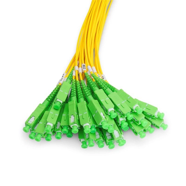
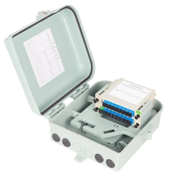
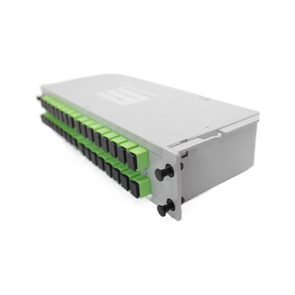
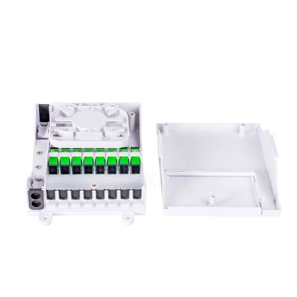
An Optical Splitter (also known as a fiber optic splitter or beam splitter) is a passive optical power management device. “Passive” means it needs no electricity. It requires no power source to work. Imagine a water pipe. One large pipe brings water into a building. 📦 For purchasing, use the RP Photonics Buyer's Guide for beam splitters. It provides an expert-curated supplier directory, buyer-focused technical background information, and structured selection criteria to support professional procurement decisions. What are Beam Splitters? A beam splitter (or. Beamsplitters are optical components used to split incident light at a designated ratio into two separate beams. Additionally, beamsplitters can be used in reverse to combine two different beams into a single one. Beamsplitters are often classified according to their construction: cube or plate. A beam splitter or beamsplitter is an optical device that splits a beam of light into a transmitted and a reflected beam. It is a crucial part of many optical experimental and measurement systems, such as interferometers, also finding widespread application in fibre optic telecommunications.
[PDF]

They can be used to split unpolarized light at a 50/50 ratio, or for polarization separation applications such as optical isolation (Figure 3). Non-polarizing beamsplitters split light into a specific R/T ratio while maintaining the incident light's original. The beam splitters on the top and far right does not seem to have two rays. Is there any way i could solve this? Thank you! My Model: My Lens Data: Best answer by David. Nguyen Hi, I have looked at your file and made the following modifications for the respective configurations. Surface 8 had a. 📦 For purchasing, use the RP Photonics Buyer's Guide for beam splitters. It provides an expert-curated supplier directory, buyer-focused technical background information, and structured selection criteria to support professional procurement decisions. What are Beam Splitters? A beam splitter (or. A beam splitter or beamsplitter is an optical device that splits a beam of light into a transmitted and a reflected beam. It is a crucial part of many optical experimental and measurement systems, such as interferometers, also finding widespread application in fibre optic telecommunications. Additionally, beamsplitters can be used in reverse to combine two different beams into a single one.
[PDF]