This document provides instructions on configuring static LACP mode on a Huawei switch: create an Eth-Trunk interface, add GigabitEthernet ports as members, set the LACP priority to determine active/backup interfaces, and verify the configuration. This document provides campus networks typical configuration examples and feature typical configuration examples. "Campus Networks Typical Configuration Examples" provides typical campus network networking modes and a variety of deployment examples. The same configuration is required on the peer. This chapter describes how to configure link aggregation. Link aggregation bundles multiple Ethernet links into a logical link to increase bandwidth, improve reliability, as well as load balance traffic. Maintaining link aggregation includes monitoring the link aggregation running status and. In this comprehensive video, we delve into the intricacies of Link Aggregation Control Protocol (LACP) on Huawei switches. LACP plays a vital role in enhancing network performance, providing increased bandwidth, and ensuring high availability for critical applications. more In this comprehensive. Aggregation and access devices downstream to the core layer can automatically go online through Zero Touch Provisioning (ZTP). This section describes three automatic deployment modes, which can be selected based on the site requirements. Import information using the network plan template.
[PDF]
Run the display transceiver [interface interface-type interface-number | slot slot-id] , to view the information on the optical module interface. During use, reading optical module information helps understand its real-time operating status, enabling faster troubleshooting of link abnormalities. The following uses the. Taking the Huawei 5700 series switches as an example, the commands to view optical module information are as follows: Transceiver Type :1000_BASE_SX_SFP Connector Type :LC Wavelength(nm) :850 Transfer Distance(m) :300(50um),150(62. 5um) Digital Diagnostic Monitoring :YES Vendor Name. See the interface module via the optical display command information, including general information of the optical module, manufacturing information, and alarm information. This is tested using NetEngine40E Universal Service Router or NE40E running version 8. Sample Output: (Can see link down and not receiving any power from the neighboring device) Or can do filtering:. Today, ETU-LINK will introduce how to query the information of optical module on Huawei switch. Next, we will introduce the query instructions of relevant parameters of optical module, and view the DDM information of interface optical modules through display command. Execute the command, display.
[PDF]
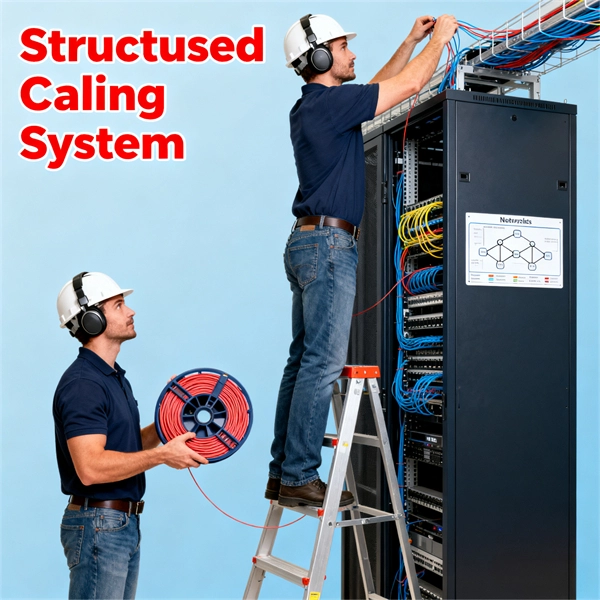
In this guide, we will walk you through the process of setting up a network switch, from selecting the right equipment to connecting and testing the network. Ethernet switches, also called network switches, connect multiple devices via Ethernet cables. In contrast, a router connects your local area network (LAN) to the internet's. A practical, current guide to planning, pulling and terminating Cat6/Cat6A cable — tools, techniques, testing and labeling for reliable results. By Thomas McCormack • Updated Mar 17, 2026 • 12 min read • Lead Technician and Engineer, Data Wire Solutions Disclosure: Some links may be affiliate. With an Ethernet cable, you can hardwire your devices to your network, providing fast and efficient. Your ethernet switch doesn't come with any ethernet cables, so you want to have some on hand when setting up your switch. You'll need one cable to connect your ethernet switch and router together (assuming you want to provide your devices with an ethernet connection to the internet), and an. A network switch is a crucial component in any modern network, enabling seamless communication between devices. By the end of this tutorial. Connecting a network switch involves physically connecting devices using Ethernet cables and configuring them as needed, ultimately expanding your network connectivity and improving network performance. Connecting a network switch is a foundational skill for anyone managing a home or small business.
[PDF]
In this video, we'll guide you through the process of configuring a Huawei Switch for your network. Whether you're setting up a new switch or optimizing your existing network infrastructure, this step-by-step tutorial will help you get the job done efficiently. This document provides campus networks typical configuration examples and feature typical configuration examples. "Campus Networks Typical Configuration Examples" provides typical campus network networking modes and a variety of deployment examples. This document is for switches running V200R003C00 and later. In this video, we'll guide you. Saving Configuration: Save changes to make the configuration permanent: Checking Settings: Use commands like display user-interface console 0 to verify correct configuration. Exiting the Device: Log out of the device after completing the configuration. Enabling Telnet Service and Granting Access on. The Combo interface, also known as the optical-electrical multiplexing interface, consists of two Ethernet ports (one optical and one electrical) on the device panel, and there is only one forwarding interface inside the device.
[PDF]
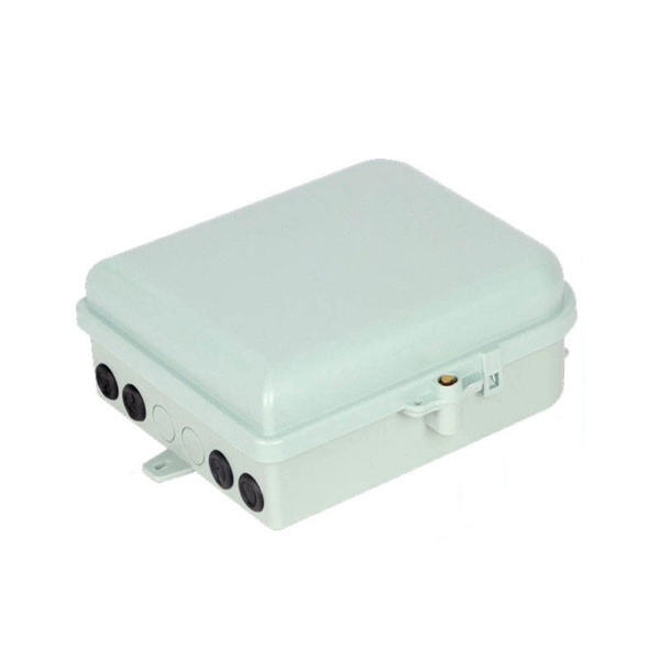
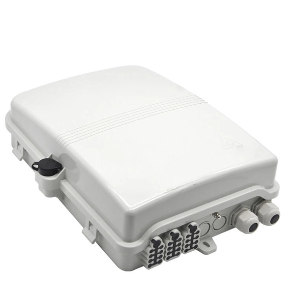
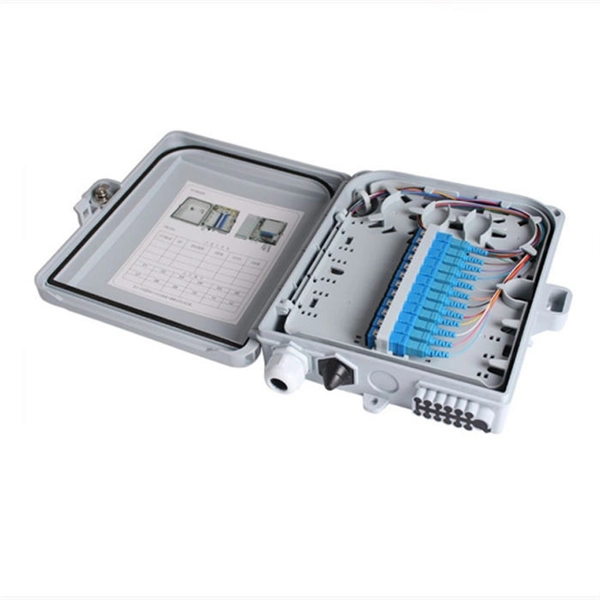
Learn how to install a centered light switch or outlet in the middle of a 2-gang electrical box to provide extra room for bulky wiring. Use the links to find. An electrical box cover serves a dual function in any residential or commercial setting, whether for a junction box, switch, or outlet. This plate provides a barrier to protect the delicate wiring connections within the electrical box from damage and debris. Simultaneously, it conceals the. In this guide, we'll break down everything you need to know to install a distribution box correctly and confidently. Choose the right box based on environment (indoor/outdoor), load capacity, and durability. Check for proper IP/NEMA ratings and material quality. Ensure safe placement: install in. The new junction box and exposed work cover for the electrical outlet and light switch are prewired before installing in the attic. Use the links to find the correct solution: 1 Gang. Choosing and installing a light switch box cover is a simple, five-minute DIY project that instantly upgrades a room's appearance. It primarily involves turning off the power, removing two screws, and attaching the new plate. A switch box is a crucial component of any electrical system, allowing you to control the flow of electricity to various devices or lights.
[PDF]
This is a walkthrough for the TASK Master side mission in Borderlands 4. Read on to follow the objectives and clear the mission, as well as how to replace power core. TASK Master is part of a questline that starts with The Kairos Job. A core switch in networking serves as the high-capacity backbone, italic centralizing data flow and ensuring efficient communication between different network segments. Simply put, it's the kingpin that keeps your network humming. You may also want to know: Can a Nintendo Switch Play DS Games? ·. To prevent electrostatic damage (ESD) to electronic components, you must be sure that you are grounded while handling electronic components. Components include, but are not limited to, all switch modules. Connect the switch to the facility earth ground. Attach an ESD wristband to your arm and be. Unless you power on layer 3 switch; specifically 3650, you will not be able to configure it or even access the command line interface (CLI). In this post, I will show you how to power on Layer 3 switch in packet tracer; both the steps you need to take and a video demonstrations of the process Here. In such high-capacity ethernet networks, switches are crucial as they direct data and transmit signals to the addressed devices. There are different types of enterprise switches that perform various roles in these layer-based or hierarchical ethernet networks. Complete The Kairos Job, Free for the TASKing, and TASK and Ye.
[PDF]
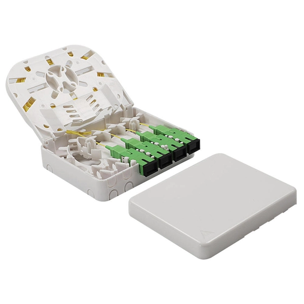
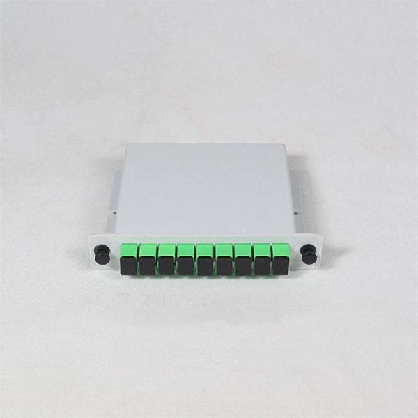
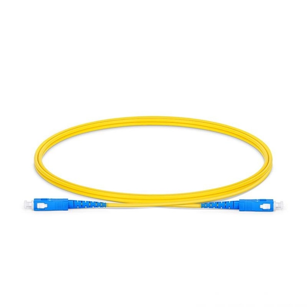
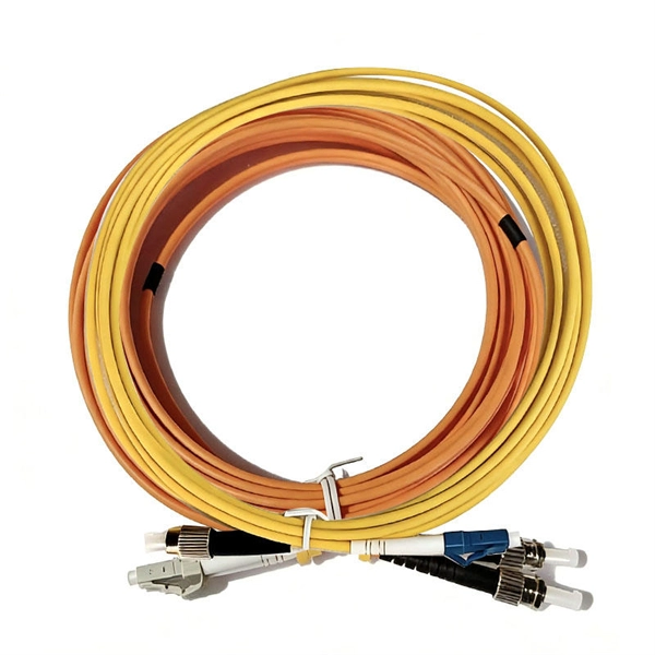
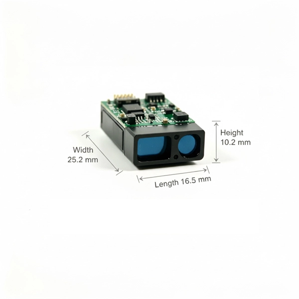
To connect a fiber, align the optical connector with the optical port and gently insert the optical fiber into the port. A fiber adapter (also called a flange) is a fiber connection component. An active optical cable (AOC) is a fixed-length optical fiber with optical modules at both ends. It can be directly connected to an optical port on a device. Table 10-3 lists the models and attributes of. Optical modules are widely used in switches, network interface cards (NICs), routers, and other communication devices. During use, reading optical module information helps understand its real-time operating status, enabling faster troubleshooting of link abnormalities. Solution: To solve this problem, you can follow these steps: Check if the fiber and optical modules are compatible. Perform a. All other trademarks and trade names mentioned in this document are the property of their respective holders. The purchased products, services and features are stipulated by the contract made between Huawei and the customer. Major causes of the interface physically down event include hardware and software failures. Hardware failures: include hardware. Step 1: Antistatic strap must be worn to prevent static damage. Step 2: Take out the optical module, ring and label up, the gold finger is facing down, Note that the right and the negative can not be reversed.
[PDF]
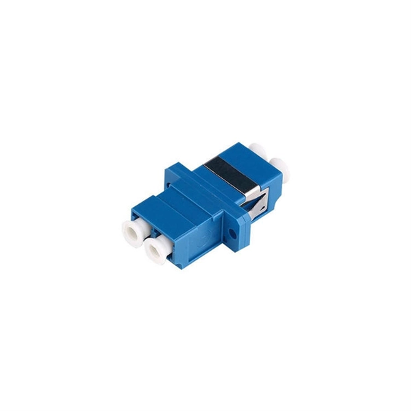
Most modern fiber-enabled network switches require an SFP transceiver module featuring a duplex (two strand) multimode OM3 or duplex single mode OS2 connection with LC connectors. Direct attach cables with pre-terminated SFP connections may also be used. Download. CONFIGURING THE SWITCH IN DESIGO CC/CERBERUS DMS. CYBERSECURITY DISCLAIMER. 44. This tutorial will explain the steps required to configure fiber optics on a Cisco switch and ensure proper connectivity in your network. Contains package contents and instructions for unpacking, setting up and adjusting the optical power of your FOS unit. Contains operating specifications and pinout information. You can access documentation for Ocean Optics. Upgrades Occasionally, you may find that you need Ocean Optics to make a change or an upgrade to your system. To facilitate these changes, you must first contact Customer Support and obtain a Return Merchandise Authorization (RMA) number. Page 8 About This Manual 000-10000-040-02-0505. Chapter 1. This document describes how to troubleshoot fiber optic interfaces by addressing some of the fiber optic module and cabling specifications. The information in this document is based on all Catalyst 9000 Series switches. This includes Doppler. Fiber optic cabling is increasingly used to connect network switches and other datacom equipment, especially in long-distance and mission-critical applications. Fiber provides: Increased internet signal bandwidth.
[PDF]
Use the command display transceiver to view the optical module information of all optical ports, and use the command display transceiver interface interface-type interface-number to view the optical module information of a specific optical port. Related Information Video Identify a Huawei-Certified Optical Module Run the display transceiver [ interface interface-type interface-number | slot slot-id ] [ verbose ]. Here is an example on how to query or display optical power of an interface in a Huawei Router. This is tested using NetEngine40E Universal Service Router or NE40E running version 8. The specific viewing information is as follows:. Optical modules are widely used in switches, network interface cards (NICs), routers, and other communication devices. During use, reading optical module information helps understand its real-time operating status, enabling faster troubleshooting of link abnormalities. Transceiver Type : 1000 _BASE_SX_SFP Connector Type :LC Wavelength(nm) : 850 Transfer Distance(m) : 300 (50 um), 150. We want to troubleshoot transceiver on Huawei router, Huawei switch, Huawei systems. 1 Show details, warning etc. from transceivers Check “Alarm information” section for warnings, LOS Alarm means no inbound signal, execute display this to check shutdown mode, execute undo shutdown if necessary.
[PDF]
To replace an electrical switch, expect to spend about $80 to $120 on average. It's all relative, but $23k for a pair of core switches is cheap IMO. Cisco would try to charge A LOT MORE. I removed all. FI per port to connect to Nexus switches. 9Ghz, 6Core Broadwell DE CPU128GSSD,32GDRAM REMANUFACTURED. Check CORE SWITCH price from the latest Cisco price list 2022. Our core switches are EOL and have been for a long time. I need 5 core switches for $15,000 for a mid-size organization with multiple locations. Suggestions? Want to add to the discussion? Post a comment! [–] bitslammer Infosec/GRC 21 points [–] Sr. Sysadmin How many ports? What kinds of ports? L2. Unlock exclusive savings on 5/9/26 at 9am PT. Did You Find It? Save this search Request a server item Cisco Catalyst 9200CX-8P-2E Compact Switch, 8-Port PoE+, 240W, Network Essentials. MikroTik CRS504-4XQ-IN Cloud Router Switch 650MHz 4xQSFP28 Compatible with 40G. There are no specific requirements for this document. The information in this document was created from the devices in a specific lab environment. it's an old 3560 catalyst with a pretty basic configuration.
[PDF]
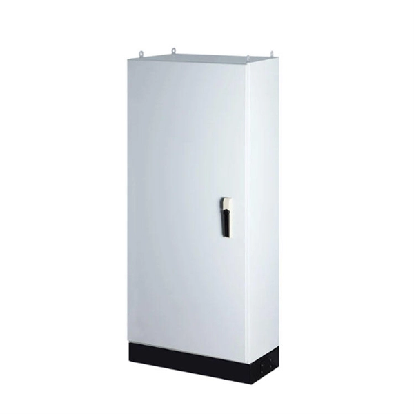
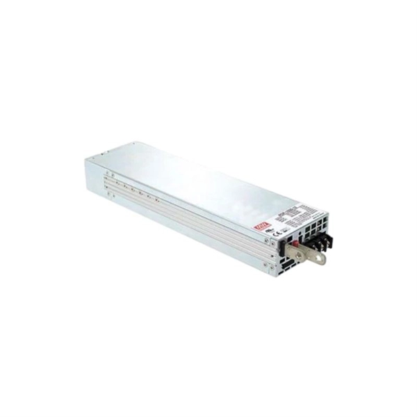
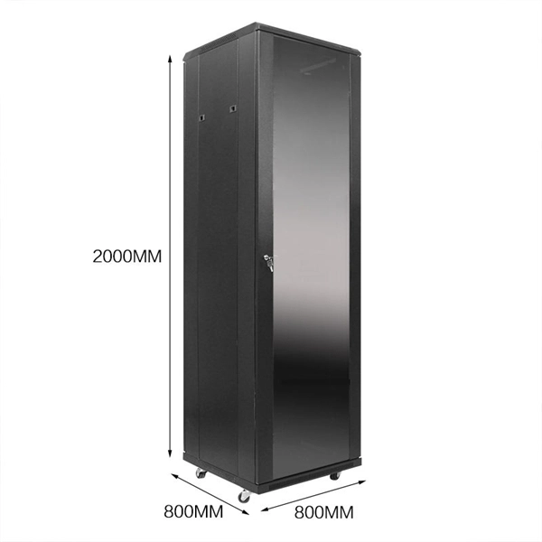
The weight of an empty server rack depends on the dimensions and features such as doors, locks, cable management features, sliding drawers, and other options. The construction of the rack also plays a role. Generally speaking, however, a 42U server rack will weigh between 275 and 350. 1288 V3 is a standard 1U, 2-socket rack server. It supports Intel® Xeon® E5-2600 v3 and v4 series processors with up to 20 cores per processor, unlocking superior performance for nterprises' computing-intensive applications. Designed for cloud computing applications, enterprise applications. L-shaped guide rails: apply only to Huawei cabinets. Static rail kit: applies to cabinets with a distance of 543. ) between the front and rear mounting bars. 98. CloudDC provides different iRack specifications for different service scenarios. Was this page helpful? Thank you very much for your feedback. We will continue working. Discover Huawei 42U racks with 600-1200mm depth, tempered glass/mesh doors, and OEM support. Ideal for data centers, server & storage setups. The Huawei SmartAX F01T500 is an outdoor cabinet with dimensions of 1600 x 1350 x 460 mm. It is divided into two sections, each with its own door. The left section includes 21" Rack rails with a total height of 25U, with a ventilation panel and a power distribution panel located at the top.
[PDF]
This document describes the configuration of Ethernet services, including configuring link aggregation, VLANs, Voice VLAN, VLAN mapping, QinQ, GVRP, MAC table, STP/RSTP/MSTP, SEP, and so on. This chapter describes how to configure link aggregation. Link aggregation provides link backup mechanisms, greatly improving link reliability. Link aggregation has the following advantages:. As shown in Figure 1, SwitchA and SwitchB are connected to the networks of VLAN10 and VLAN20, respectively, via Ethernet links, and there is a large amount of data traffic between SwitchA and SwitchB. The user wants to provide a larger link bandwidth between SwitchA and SwitchB to enable the same. Link Aggregation is one of the important lessons of networking. One of these examples will be for Layer 2. On a NAC network, the 802. 1X, MAC address, and Portal authentication modes are configured on the user access interfaces of a device to meet various authentication requirements. Users can access the network using any authentication mode. If multiple authentication modes are enabled, the. Link aggregation, in other words trunking, is a technique that helps to increase bandwidth by bundling multiple physical interfaces into a logical one, named Eth-trunk. Besides bandwidth increase, trunking lets us to implement load-balancing and ensure higher reliability. Few restrictions must be.
[PDF]
Wavefront shaping enables precise control of light propagation through multimode fibers, facilitating diffraction-limited focusing for applications such as high-resolution single-fiber imaging and high-power fiber amplifiers. While the theoretical intensity enhancement at the focal point is. Light from a high-power laser diode is coupled into a multi-mode fiber (diam:100 um, NA = 0. A de-speckle unit can be turned on and off to reduce any speckles that appear after light leaving the multi-mode fiber. A collimating lens (CL) after the fiber collimates the light to a certain. We present laboratory measurements demonstrating how the output beam profile from multimode fiber can be affected by the beam entry angle. In some applications, an alternative beam distribution such as a top hat or donut is desired instead of the inherent Gaussian distribution provided by typical. Light transport in a highly multimode fiber exhibits complex behavior in space, time, frequency, and polarization, especially in the presence of mode coupling. The newly developed techniques of spatial wavefront shaping turn out to be highly suitable to harness such enormous complexity: a spatial. What are the conditions for efficiently launching light into a multimode fiber? What happens to the intensity profile of light during propagation in a multimode fiber? How do bending and other disturbances affect the output beam profile? What are the challenges of maintaining single-mode.
[PDF]
This guide explains the latest EIA/TIA-598-D fiber color-coding standard used to identify fiber types, inner fiber sequences, and connector polish styles. With clear tables and updated details, it serves as a comprehensive reference for technicians handling modern fiber optic. Understanding fiber‑optic color codes is essential for any technician tasked with installing, maintaining, or troubleshooting modern fiber networks. By adopting the TIA/EIA‑598C standard, you gain a universal “language” of colors that speeds identification, reduces miswiring, and enhances safety. Color codes are used in fiber optics to identify fibers, cables and connectors. Each fiber strand is color-coded to help network technicians match, splice, and troubleshoot connections, which is especially important when you're dealing with cables that. Fiber optic color codes provide the essential identification framework that enables fiber technicians and network professionals to manage complex optical network installations efficiently. The Telecommunications Industry Association (TIA) especially launched the TIA-598 standard. This standard addresses the manufacturer's fiber color codes to follow and reference.
[PDF]
The production of cable tray elbows requires the following steps:1. Determine the angle and required radius size of t. Here is the simple solution Create two type : 90 elblow and 45 elbow In the real world, to make a 45 elbow, we need two segments, to make a 90 elbow, we need three segments I've also tried to use some geometry forms in revit but no hope. Choose suitable metal materials based on the. To cut a cable tray for a 45-degree bend, you need to make two 22. 5∘ cuts on two separate pieces of cable tray. Each cut should be 22. 5∘ from a perpendicular line drawn across the tray's width. The second piece's cut must be in the opposite direction to the first, allowing them to join and form the. The bends, tees, crosses, risers and reducers of wire mesh cable tray can be easily and quickly made live at the project by using a bolt cutter. Since the jaws of the bolt cutter drags a layer of zinc across the cut end and forms a protective layer. So I can then use the formula on different cable tray sizes and to different angles. 3 (2" CABLE FILL) F = POLYESTER 06 = 6" 45 = 45 DEG. VO = VERTICAL RADIUS THIS DRAWING AND/OR THE TECHNICAL INFORMATION CONTAINED HEREON IS THE PROPERTY OF EATON CORPORATION ("EATON"), AND IS ISSUED IN CONFIDENCE FOR EATON ENGINEERING PURPOSES ONLY AND MAY NOT BE REPRODUCED OR USED FOR ANY PURPOSE.
[PDF]