This document provides the users of USB4000 Spectrometers with instructions for setting up, calibrating and performing experiments with their spectrometer. Remote fiber optic spectroscopy is a sophisticated technique that uses fiber optic couplers, cables, and accessories to analyze samples at a distance from the spectrophotometer. The technique unlocks a range of experiments that standard UV-Vis or fluorescence instruments cannot accommodate. The. Fiber optic spectrometers have revolutionized the field of remote sensing and data acquisition, providing unprecedented flexibility and precision. These devices utilize the unique properties of fiber optics to measure and analyze the spectral composition of light, making them indispensable tools in. The Cary 60 Fiber Optic Coupler and the Cary 60 Dip Probe Coupler are optional accessories for the Cary 60 UV-Vis spectrophotometer. Both accessories convert the Cary 60 UV-Vis into a remote fiber optic measurement system. Contains descriptive. Near-Infrared Spectroscopy (NIR) offers important advantages in analytical chemistry, particularly in process monitoring and quality control across various industries. This paper details the operational principles, methodologies, and significant advancements in NIR spectroscopy, emphasizing the. The basics of fiber optic cables and bundles and how they can be used to collect and direct light are discussed in 'An Introduction to a Spectrometer: Fiber Optic Bundles'.
[PDF]
This document describes how to use and program the Photonic Application Suite, Insertion Loss Engine. Insertion loss is measured by comparing signal power (or sound level) before and after it passes through a component or system, then expressing the difference in decibels (dB). The core process is the same across fiber optics, RF electronics, and acoustics: establish a baseline reference without. This tutorial aims to help RF engineers understand how to test and measure various RF specifications of RF power amplifiers, RF LNAs (Low-Noise Amplifiers), and RF transceivers using RF test and measurement equipment like spectrum analyzers, signal generators, and sweep oscillators. Gain is the. Coaxial cables are essential components in transmitting radio frequency (RF) signals, but they inherently attenuate these signals, a phenomenon known as cable loss or insertion loss. Yes, I would like to receive educational or promotional emails from Keysight. By clicking the button, you. Insertion loss is a critical parameter in RF engineering that refers to the loss of signal power that occurs when a component or device is inserted into a transmission line or circuit. The insertion loss measurement quantifies the effect of the resistance the cabling link offers to the transmission of the electrical signals. Insertion loss characteristics of a.
[PDF]
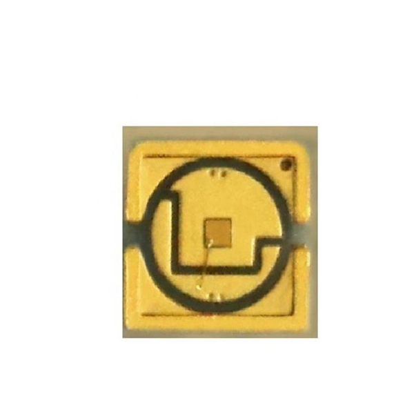
You can test a photocoupler with a multimeter. This checks if its output changes when you power its input. This gives you the most accurate test results. This detailed guide will walk you through the process of testing an optocoupler using a multimeter, covering various scenarios and providing practical advice to ensure accurate results and avoid common pitfalls. We'll explore the underlying principles, delve into different testing methods, and. In this episode #0018 of Electronic Components Testing, we reveal how to test an optocoupler (optoisolator) using a digital multimeter step by step. This simple yet powerful technique will help you detect faulty optocouplers on circuit boards without desoldering them. Always. What are the methods to test optocoupler? The quality of the optocoupler can be determined by measuring the forward and reverse resistance of its internal diode and triode. Jotrin Electronics Limited will tell you that the reliable detection methods,as follows: 1. From basic circuit design to complex industrial systems, accurate optocoupler. Optocoupler is one type of ICs, It isolates input and output section by using optical technology this feature increase safety of circuit. Optocoupler has many part number, different part number has different output type so before checking it has to use part number to research with datasheet and.
[PDF]
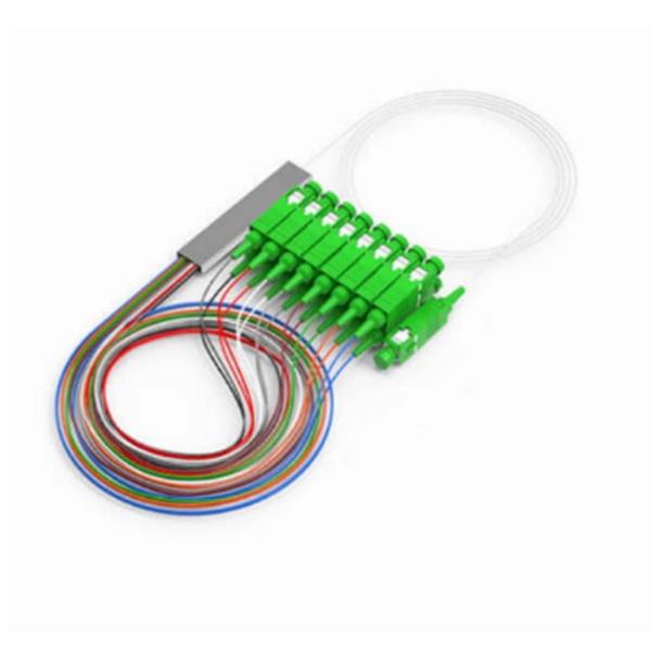
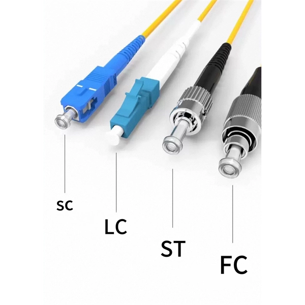
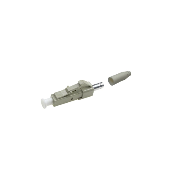
This interactive tutorial explores transmission and reflection of a light beam by three common beamsplitter designs. In addition to the task of dividing light, beamsplitters can be employed to recombine two separate light beams or images into a single path. The tutorial initializes with a cube. The fiber jumper connects the network devices at both ends and is used in the following three scenarios. FC Connector: use a metal sleeve for external reinforcement, fastened with a screw fastener. Generally used in the ODF (the most used on MDF) SC Connector: connected to the GBIC module, its. As title. It is a crucial part of many optical experimental and measurement systems, such as interferometers, also finding widespread application in fibre optic telecommunications. In its. The beam splitter has played numerous roles in many aspects of optics. For example, in quantum information the beam splitter plays essential roles in teleportation, bell measure-ments, entanglement and in fundamental studies of the photon. Electric elds E1 and E2 enter input ports 1 and 2. A beam splitter is an optical device that splits beams (such as laser beams) into two (or more) beams. Beam splitters typically come in the form of a reflective device that can split beams into exactly 50/50, half of the beam being transmitted through the splitter and half being reflected.
[PDF]
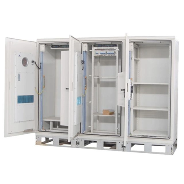
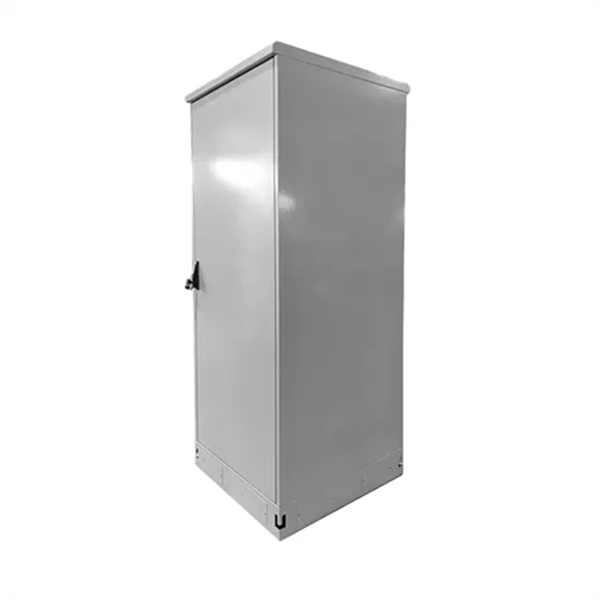
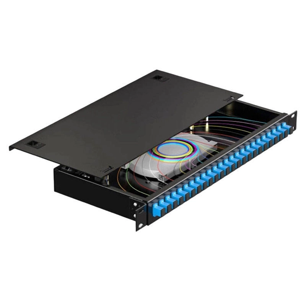
This complete guide explores everything you need to know about ODFs — from their structure, types, and key components, to installation best practices and modern design trends. Whether you're building a central office, data center, or FTTx distribution network, understanding the right ODF. In the complex architecture of fiber optic networks, the Optical Distribution Frame (ODF) serves as the linchpin for organizing, protecting, and distributing optical signals. It's where incoming and outgoing cables meet. It does four key things: Think of it as the central hub for your fiber network. Without it, cables get tangled. All. How to Splice 4-Fiber Optic Cable with ODF | Step-by-Step Fiber Optic Splicing Tutorial. Whether you are a beginner or a professional in fiber optic networking, this guide will help you splice. Fiber Optic Infrastructure Specialist (19Y Exp) | One-Stop: Fiber Cables, Distribution Boxes, Splice Closures, Splitters & Patch Cords | Sourcing for ISPs & Contractors in EU/Africa. It is used to terminate, connect, and distribute optical fibers, and it can be installed in various environments such as data centers, telecom rooms, and central offices. In this article.
[PDF]
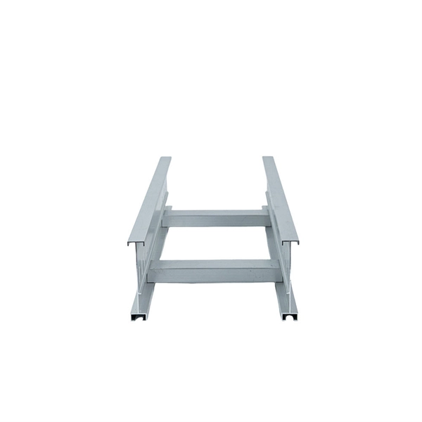
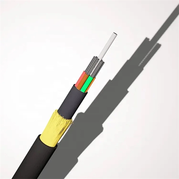
This guide reveals the secrets to fusion splicing with little fluff—just proven, straightforward techniques refined from years of work in the field. In this guide, you will find a chronological description of the fusion splicing process, the principal technical standards, and answers to the real-life questions network engineers and procurement teams may have. The guide provides the complete workflow, covering safety precautions, tool selection, fiber preparation, fusion operation, quality control, and. Summary: Fiber color codes, defined by the TIA-598-C standard, help technicians quickly identify individual fibers, buffer tubes, and connectors in multi-strand cables. Using proper color coding makes installation easier, speeds up troubleshooting, reduces downtime, and supports future network. When a tech opens a fiber optic cable to prepare it for splicing, they will find a colorful bundle of buffer tubes as on this armored cable. The colors of the buffer tubes and likewise the fibers in the tubes provide the identification the tech needs to complete the splicing of the fibers as the. Fusion splicing is the bedrock of high-performance fiber optic networks, enabling seamless signal transmission through permanent, low-loss fiber joins. By adopting the TIA/EIA‑598C standard, you gain a universal “language” of colors that speeds identification, reduces miswiring, and enhances safety.
[PDF]
This video makes connecting your fiber optic cable to your router a breeze! We'll guide you through the entire process step-by-step, ensuring a smooth and hassle-free experience. Our Experts are helping user's, who are facing issues with their tech gadgets like Router . In this guide, we'll walk you through how to connect a fiber optic cable to a router safely and efficiently. Why Use Fiber Optic Internet? Before diving into the setup, let's quickly recap why fiber optics are worth the effort: Lightning-fast speeds (up to 1 Gbps or higher). If you. The fiber optic cable does not plug directly into a standard home router because the signal type must be translated. The fiber line terminates at the Optical Network Terminal (ONT), which is typically supplied and installed by the internet service provider. This comprehensive guide combines industry standards with field-tested practices to ensure you achieve a rock-solid. Turn on the router; 2. Plug one end of the network cable into either of the router's ports and the other end into the Internet wall socket or the LAN port of an optical modem or ADSL modem. Does it help? Copyright © 2010 - 2026 Xiaomi. Check compatibility: Before you begin, make sure your router supports fiber optic connection. Not all routers can connect directly to a fiber cable, so it is important to verify this information before continuing.
[PDF]
A spectrophotometer is a piece of spectroscopy equipment measures the amount of light absorbed by a sample. This measurement can be useful in many research applications: To identify materials by mapping molecular absorption profiles. To work out solute concentrations in solutions. Specifically, a UV-Visible Spectrometer measures the absorption or transmission of light in the ultraviolet (UV) and visible (Vis) regions of the electromagnetic. A spectrometer is a scientific instrument that analyzes light to reveal information about materials. It functions by separating light into its constituent wavelengths, much like a prism splits sunlight into a rainbow. This analytical capability makes spectrometers valuable tools across many fields. Spectrophotometry is an experimental technique that is used to measure the concentration of solutes in a specific solution by calculating the amount of light absorbed by those solutes. It is widely used in laboratories to analyze various substances, from liquids to gases. Here's a step-by-step guide on how to use a spectrophotometer. When you use spectrophotometry, you gain skills that help in many science fields. This guide makes spectroscopy simple by showing you how to use teaching tools and real experiments. The basic principle is that each compound absorbs or transmits light over a certain range of wavelength. This measurement can.
[PDF]
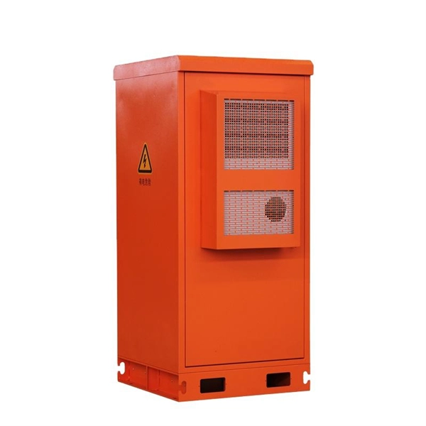
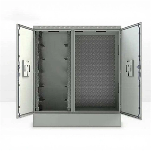
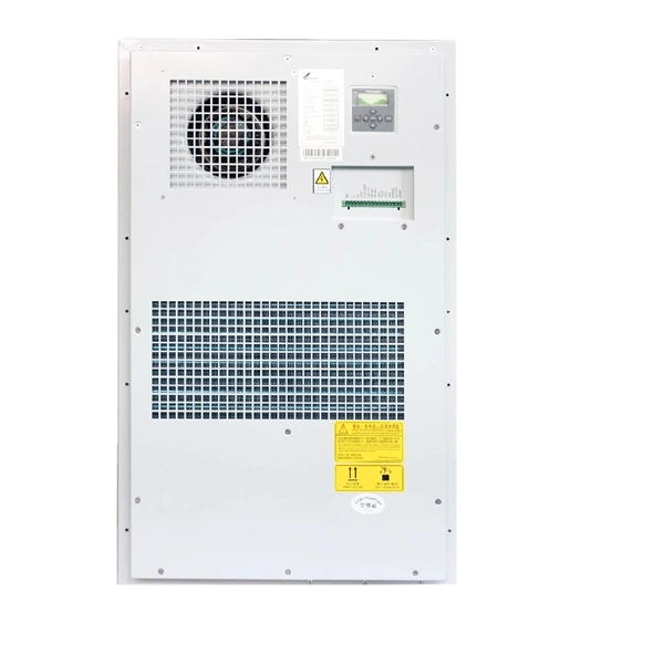
In this guide, we'll walk you through the essential steps to maximize the benefits of your power distribution box. Converts high voltage into safe, usable outputs for various applications. Essential for industries like construction, disaster recovery, and entertainment. Whether you are an electrical contractor or a construction brigade, knowing how to properly and safely install distribution boxes is the basis of ensuring the safe operation of the entire system. This article details the process of installing them, which helps you comprehend distribution boxes. In modern electrical systems, cable distribution boxes (also known as electrical distribution boxes or distribution boxes) play a crucial role as the key hub for managing, distributing, and protecting circuits. more Welcome to our channel! In this video. An electrical panel box, also known as a breaker box or a distribution board, is a crucial component of any electrical system. It serves as a central hub for distributing electricity throughout a building, ensuring that power is delivered safely and efficiently to all the required locations. These units are equipped with GFCI protection, ensuring safety across diverse applications 1.
[PDF]
Press the Percent T/A selector to select Percent Transmittance or Percent Absorbance mode. Locate the wavelength dial beside the sample chamber and set it to the desired wavelength. Don gloves and wipe a cuvette with a lab wipe to clean it and remove any fingerprints. A spectrometer is an analytical tool used across various scientific disciplines to measure how a substance interacts with light. Specifically, a UV-Visible Spectrometer measures the absorption or transmission of light in the ultraviolet (UV) and visible (Vis) regions of the electromagnetic. How did a Spectrophotometer help scientists identify a species of bacteria that can clean up pollution? What is a Spectrophometer anyway, and how do you use one? In this video, Jayme Dyer answers these questions and provides practical Pro-Tips for how to use a Spectrophotometer in the lab. It consists of two parts: a spectrometer and a photometer. The spectrometer provides light at a specific wavelength. When you use spectrophotometry, you gain skills that help in many science fields. You will see that. Here's a step-by-step guide to using a spectrophotometer effectively. Blank Calibration: Fill a. Turn the Device on and Allow It to Warm Up 2. Clean and Prepare Containers and Control Samples 3. Standardize the Device According to Manufacturer's Directions 4. Choose Your Measurement Comparisons and Capture Data Spectrophotometric solutions simplify the science of quantifying chromatic data for.
[PDF]
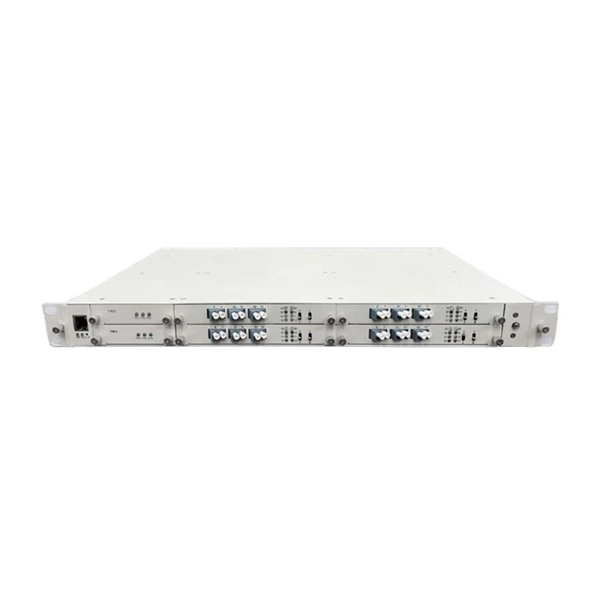
Insert a compatible SFP transceiver into the converter's port, making sure it matches the network's media type and speed. Then, connect one end of the fiber cable to the transceiver and the other to the appropriate port on a switch, router, or another media converter. Fiber media converters translate copper's electrical signals into fiber's optical signals, and back again. This allows networks to extend beyond the 100 m copper limit while gaining higher bandwidth and resistance to electromagnetic interference. In the illustrated setup, each LAN links to a. A fiber media converter is a networking device that allows you to convert a signal from one medium to another. This allows you to connect devices that use different types of cabling, such as a computer. While fiber optic ports are becoming increasingly common on networked electronics, the majority of connected devices still rely on RJ45 twisted pair connections. To help bridge the copper-fiber divide, media converters and transceiver modules (also known as SFPs or mini-GBICs) are often required. Use Fiber Media Converter in Your Network Media converters today are widely deployed in all. It is a device used to convert fiber optic cables to Ethernet cables to provide better connectivity. It is necessary to convert fiber optic signals to Ethernet signals because many network devices can only communicate with Ethernet signals. Fiber optic cables are known for the unmatched speed.
[PDF]
This guide provides cost estimates in USD with low, average, and high ranges and explains what drives these prices. Assumptions: region, service call for electrical work, permit requirements, and box type vary by locality. The total project range typically falls between $1,500. How much does it cost to replace an outside electrical meter box? Get free estimates for your project or view our cost guide below: Electric meter box replacement costs $500 to $2,100 on average, depending on the meter size, location, installation complexity, and code requirements. New outside. Homeowners typically pay a lump-sum for electric meter installation ranging from modest upgrades to full service upgrades. The main drivers are meter type, service size, local permitting, and whether utility work is required. The price range below reflects common U. scenarios and includes both. Replacing a home meter box typically costs between US $500–$2,100, though large or complex jobs — like 400-amp or full service upgrades — may reach $5,000+, depending on wiring, permits, and labor. Professional installation ensures NEC compliance, proper grounding and bonding, and successful inspection approval. Cost ranges reflect total project price plus typical per-unit components.
[PDF]
In this video, we'll walk you through the process of wiring a home distribution box with a detailed connection diagram. Whether you're an electrician or a DIY enthusiast, this guide will help you understand the basics of home electrical distribution. more Welcome to our channel! In this video. Understanding the wiring diagram of an electrical panel box is essential for electricians and homeowners alike, as it allows them to troubleshoot any electrical issues, carry out repairs, or make additions to the system. The electrical panel box wiring diagram provides a visual representation of. A distribution board or distribution box is where the main power supply is distributed to multiple loads. And all the switching and protective devices are installed in the distribution box. Single Phase Distribution Box generally consists of Double Pole MCBs, Single Pole MCBs, and RCCBs. Connect the two hot conductors (typically black and red) to the line terminals of the main disconnect switch. Tighten each lug to 250 inch-pounds using a torque wrench. What is Distribution Board? Distribution board.
[PDF]
Converting multimode fiber to single-mode fiber can improve network performance and future-proof infrastructure. This guide will walk you through the methods, challenges, and best practices for successfully converting multimode to . This guide will break down the professional methods to achieve seamless single-mode to multi-mode conversion, ensuring your network integrity and performance. 📝 Why Can't You Directly Connect SMF and MMF? At its heart, the incompatibility is physical. The core size of multi-mode fiber is. How can we convert the multimode to a singlemode fiber system? This complete guide will provide answers to these questions. Mode conversion is typically required when: FlexPoint unmanaged Fiber-to-Fiber Media Converters provide multimode to single-mode conversion, and support a variety of network. Fiber mode conversion, especially multimode to single-mode fiber conversion (MMF-to-SMF conversion) is required when the distance is an important parameter to consider in optical applications. In this tutorial, three methods will be introduced to support mode conversion from multimode to. Multimode fiber (MMF) and single-mode fiber (SMF) are two types of fiber optic cables utilized for transmitting light signals over extended distances (For details, please refer to the blog post “ Choosing the Right Fiber Optic Cable: Singlemode vs Multimode “). The primary distinction between them.
[PDF]
Calculate power supply wattage by multiplying the total power consumption of all PC parts by 1. This article explains how to check CPU and GPU power usage, estimates for other components, the reason for multiplying by 1. 5, and introduces a calculation tool. Calculating the power supply unit's wattage may seem troublesome, but there is also a tool that calculates the power supply wattage just by selecting parts, so please use it. Modern systems draw power primarily from the CPU and GPU, with motherboards, memory, storage, and peripherals contributing smaller amounts to total system load. High-performance processors in 2026. Our advanced power calculator tool precisely calculates the wattage needed based on your selected components, ensuring optimal performance and compatibility. Select your components, get accurate power estimates, and find the right PSU with proper headroom and efficiency rating. It can be used to select a proper power supply unit for your system. It can also be used to calculate the cost of. Calculate your PC's exact power consumption and get instant PSU recommendations with safety headroom. Build with confidence using accurate TDP data for CPUs, GPUs, and all components. Stop guessing PSU wattage and avoid expensive mistakes.
[PDF]