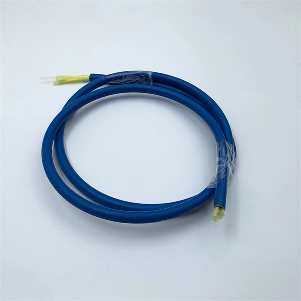
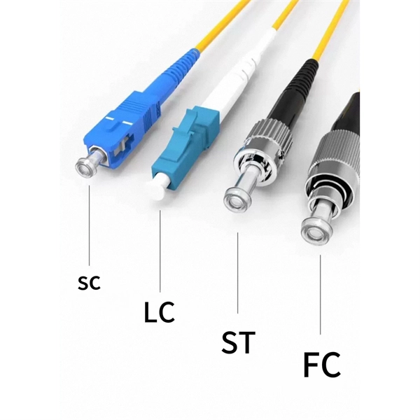
This interactive tutorial explores transmission and reflection of a light beam by three common beamsplitter designs. In addition to the task of dividing light, beamsplitters can be employed to recombine two separate light beams or images into a single path. The tutorial initializes with a cube. The fiber jumper connects the network devices at both ends and is used in the following three scenarios. FC Connector: use a metal sleeve for external reinforcement, fastened with a screw fastener. Generally used in the ODF (the most used on MDF) SC Connector: connected to the GBIC module, its. As title. It is a crucial part of many optical experimental and measurement systems, such as interferometers, also finding widespread application in fibre optic telecommunications. In its. The beam splitter has played numerous roles in many aspects of optics. For example, in quantum information the beam splitter plays essential roles in teleportation, bell measure-ments, entanglement and in fundamental studies of the photon. Electric elds E1 and E2 enter input ports 1 and 2. A beam splitter is an optical device that splits beams (such as laser beams) into two (or more) beams. Beam splitters typically come in the form of a reflective device that can split beams into exactly 50/50, half of the beam being transmitted through the splitter and half being reflected.
[PDF]
Fiber Connection: Locate the optical port on your router and carefully insert the fiber cable's connector, ensuring a snug fit. Click it into place if it has a locking mechanism. Power Up: Connect the power cords to your router and any additional devices (ONT, media converter) and. Proper connection of fiber optic cables is essential to harness these benefits fully, as even minor errors can lead to significant performance issues like signal loss. This article will guide you through the necessary tools, materials, and methods on how to connect fiber optic cables effectively. Fiber optic internet delivers blazing-fast speeds and reliable connectivity, making it a top choice for modern homes and businesses. However, setting up a fiber optic connection to your router can seem daunting if you're unfamiliar with the process. Before you start, gather the right tools. You don't want to dig around mid-job for something small but essential. Each tool helps you protect the fiber. The process to connect fiber optic cable to router requires careful attention to detail, but I'll walk you through every critical step with the precision and clarity you deserve. The fiber. The process involves a combination of national infrastructure, local engineering, and property-level setup. In this guide, we'll break down the fiber installation process from start to finish and explain key components such as fiber cabinets, flower pods, ducting, and ONT setup. What Is Fiber Optic.
[PDF]
This video makes connecting your fiber optic cable to your router a breeze! We'll guide you through the entire process step-by-step, ensuring a smooth and hassle-free experience. Our Experts are helping user's, who are facing issues with their tech gadgets like Router . In this guide, we'll walk you through how to connect a fiber optic cable to a router safely and efficiently. Why Use Fiber Optic Internet? Before diving into the setup, let's quickly recap why fiber optics are worth the effort: Lightning-fast speeds (up to 1 Gbps or higher). If you. The fiber optic cable does not plug directly into a standard home router because the signal type must be translated. The fiber line terminates at the Optical Network Terminal (ONT), which is typically supplied and installed by the internet service provider. This comprehensive guide combines industry standards with field-tested practices to ensure you achieve a rock-solid. Turn on the router; 2. Plug one end of the network cable into either of the router's ports and the other end into the Internet wall socket or the LAN port of an optical modem or ADSL modem. Does it help? Copyright © 2010 - 2026 Xiaomi. Check compatibility: Before you begin, make sure your router supports fiber optic connection. Not all routers can connect directly to a fiber cable, so it is important to verify this information before continuing.
[PDF]
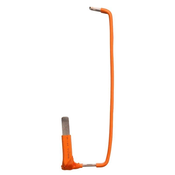
The fastest way to test a fluorescent tube is with a multimeter set to continuity mode. Each end of the tube has two pins connected by a thin filament inside the glass. If either filament is broken, the tube is dead. The whole test takes about 30 seconds per tube once you know what. Knowing how to use a multimeter to check an LED tube light is a valuable skill for homeowners, electricians, and anyone involved in maintaining lighting systems. Perhaps it's a simple wiring problem, a. One essential tool for diagnosing LED tube light issues is a multimeter. This process measures electrical resistance to determine if the tube has suffered an internal failure before replacing the bulb or investigating the ballast. If you don't have a multimeter to use, a simple coin cell battery holder with leads will let you know. Yes, you absolutely can test an LED light with a multimeter! It's a straightforward process that helps you figure out if your LED is working or if it's the source of a problem in your circuit.
[PDF]
This document provides the users of USB4000 Spectrometers with instructions for setting up, calibrating and performing experiments with their spectrometer. Remote fiber optic spectroscopy is a sophisticated technique that uses fiber optic couplers, cables, and accessories to analyze samples at a distance from the spectrophotometer. The technique unlocks a range of experiments that standard UV-Vis or fluorescence instruments cannot accommodate. The. Fiber optic spectrometers have revolutionized the field of remote sensing and data acquisition, providing unprecedented flexibility and precision. These devices utilize the unique properties of fiber optics to measure and analyze the spectral composition of light, making them indispensable tools in. The Cary 60 Fiber Optic Coupler and the Cary 60 Dip Probe Coupler are optional accessories for the Cary 60 UV-Vis spectrophotometer. Both accessories convert the Cary 60 UV-Vis into a remote fiber optic measurement system. Contains descriptive. Near-Infrared Spectroscopy (NIR) offers important advantages in analytical chemistry, particularly in process monitoring and quality control across various industries. This paper details the operational principles, methodologies, and significant advancements in NIR spectroscopy, emphasizing the. The basics of fiber optic cables and bundles and how they can be used to collect and direct light are discussed in 'An Introduction to a Spectrometer: Fiber Optic Bundles'.
[PDF]
Press the Percent T/A selector to select Percent Transmittance or Percent Absorbance mode. Locate the wavelength dial beside the sample chamber and set it to the desired wavelength. Don gloves and wipe a cuvette with a lab wipe to clean it and remove any fingerprints. A spectrometer is an analytical tool used across various scientific disciplines to measure how a substance interacts with light. Specifically, a UV-Visible Spectrometer measures the absorption or transmission of light in the ultraviolet (UV) and visible (Vis) regions of the electromagnetic. How did a Spectrophotometer help scientists identify a species of bacteria that can clean up pollution? What is a Spectrophometer anyway, and how do you use one? In this video, Jayme Dyer answers these questions and provides practical Pro-Tips for how to use a Spectrophotometer in the lab. It consists of two parts: a spectrometer and a photometer. The spectrometer provides light at a specific wavelength. When you use spectrophotometry, you gain skills that help in many science fields. You will see that. Here's a step-by-step guide to using a spectrophotometer effectively. Blank Calibration: Fill a. Turn the Device on and Allow It to Warm Up 2. Clean and Prepare Containers and Control Samples 3. Standardize the Device According to Manufacturer's Directions 4. Choose Your Measurement Comparisons and Capture Data Spectrophotometric solutions simplify the science of quantifying chromatic data for.
[PDF]
You can test a photocoupler with a multimeter. This checks if its output changes when you power its input. This gives you the most accurate test results. This detailed guide will walk you through the process of testing an optocoupler using a multimeter, covering various scenarios and providing practical advice to ensure accurate results and avoid common pitfalls. We'll explore the underlying principles, delve into different testing methods, and. In this episode #0018 of Electronic Components Testing, we reveal how to test an optocoupler (optoisolator) using a digital multimeter step by step. This simple yet powerful technique will help you detect faulty optocouplers on circuit boards without desoldering them. Always. What are the methods to test optocoupler? The quality of the optocoupler can be determined by measuring the forward and reverse resistance of its internal diode and triode. Jotrin Electronics Limited will tell you that the reliable detection methods,as follows: 1. From basic circuit design to complex industrial systems, accurate optocoupler. Optocoupler is one type of ICs, It isolates input and output section by using optical technology this feature increase safety of circuit. Optocoupler has many part number, different part number has different output type so before checking it has to use part number to research with datasheet and.
[PDF]
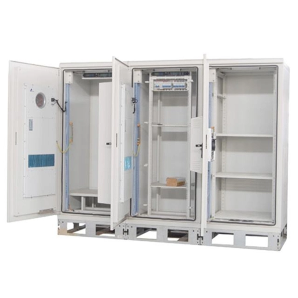
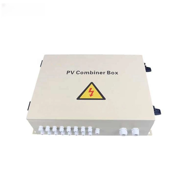
In this guide, we'll walk you through the essential steps to maximize the benefits of your power distribution box. Converts high voltage into safe, usable outputs for various applications. Essential for industries like construction, disaster recovery, and entertainment. Whether you are an electrical contractor or a construction brigade, knowing how to properly and safely install distribution boxes is the basis of ensuring the safe operation of the entire system. This article details the process of installing them, which helps you comprehend distribution boxes. In modern electrical systems, cable distribution boxes (also known as electrical distribution boxes or distribution boxes) play a crucial role as the key hub for managing, distributing, and protecting circuits. more Welcome to our channel! In this video. An electrical panel box, also known as a breaker box or a distribution board, is a crucial component of any electrical system. It serves as a central hub for distributing electricity throughout a building, ensuring that power is delivered safely and efficiently to all the required locations. These units are equipped with GFCI protection, ensuring safety across diverse applications 1.
[PDF]
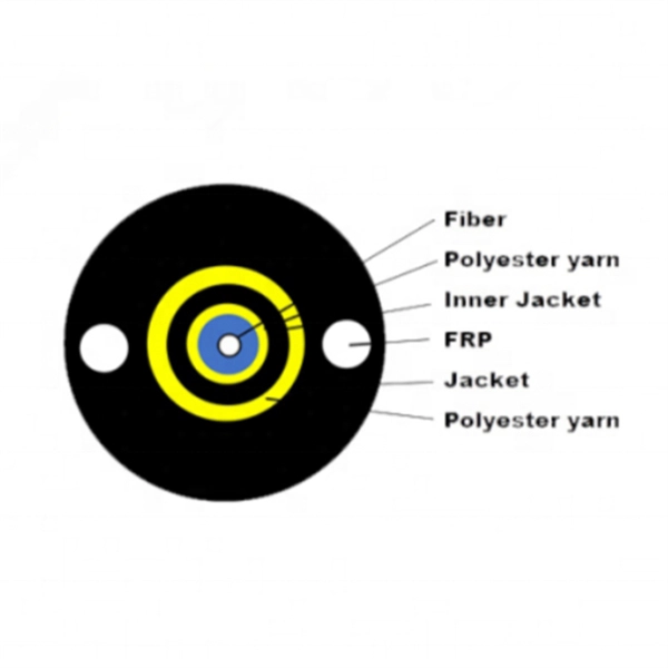
This guide reveals the secrets to fusion splicing with little fluff—just proven, straightforward techniques refined from years of work in the field. In this guide, you will find a chronological description of the fusion splicing process, the principal technical standards, and answers to the real-life questions network engineers and procurement teams may have. The guide provides the complete workflow, covering safety precautions, tool selection, fiber preparation, fusion operation, quality control, and. Summary: Fiber color codes, defined by the TIA-598-C standard, help technicians quickly identify individual fibers, buffer tubes, and connectors in multi-strand cables. Using proper color coding makes installation easier, speeds up troubleshooting, reduces downtime, and supports future network. When a tech opens a fiber optic cable to prepare it for splicing, they will find a colorful bundle of buffer tubes as on this armored cable. The colors of the buffer tubes and likewise the fibers in the tubes provide the identification the tech needs to complete the splicing of the fibers as the. Fusion splicing is the bedrock of high-performance fiber optic networks, enabling seamless signal transmission through permanent, low-loss fiber joins. By adopting the TIA/EIA‑598C standard, you gain a universal “language” of colors that speeds identification, reduces miswiring, and enhances safety.
[PDF]
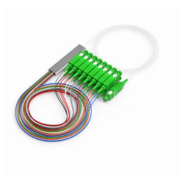
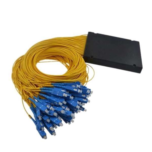
A PLC Splitter takes one optical signal and splits it into many outputs. This helps share signals in fiber optic networks. Pick the split ratio that matches what you need. Lower ratios work for fewer users. Choose the connector type like SC, LC, or FC. This. The optical splitter is an important passive device in the optical fiber link. It generally has one or two input ends and many outputs end for laser signal distribution. This article will explain the. Planar Lightwave Circuit (PLC) splitters play a vital role in modern fiber optic communication networks by enabling the efficient distribution of high-speed optical signals. It is one of the core components in Passive Optical Networks (PON) and is widely used in FTTx deployments, where a single fiber connection. This video provides a step-by-step guide on how to efficiently install optical splitter into a fiber terminal box, demonstrating a professional and reliable deployment for optical distribution network solution ( https://www. com/c/optical-distribu. more This video provides a step-by-step.
[PDF]
A neat, well-organized subpanel bundles wires to conserve space and improve access. Ideally, wire groups are installed in layers and wires are bent at right angles to buses or breakers. Label short sheathing sections (slugs) to indicate which circuits wires serve. Choose the right box based on environment (indoor/outdoor), load capacity, and durability. Check for proper IP/NEMA ratings and material quality. Ensure safe placement: install in dry, accessible areas with good ventilation and at appropriate height (typically ~1. Practice good wiring: secure. Box installation: Make sure that Distribution box has been correctly installed and fixed. Material preparation: Prepare the required circuit breakers, wires, wiring ties and other materials, and ensure that they meet the design drawings and installation requirements. And all the switching and protective devices are installed in the. Wiring distribution panels serve as the central hub and nerve center, routing power from the main service feed to multiple circuits. When setting up such a significant component of industrial, commercial, and utility applications, it's essential to get everything right. Labeling cables at outlets is.
[PDF]
This step-by-step guide aims to provide a comprehensive understanding of the techniques and considerations involved in successfully connecting optical fibers, offering invaluable insights for professionals and enthusiasts in the field. In high-speed data networks, the seamless integration of fiber optic cables with SFP (Small Form-Factor Pluggable) modules is critical for reliable signal transmission. SFP transceivers bridge electrical and optical signals, making them indispensable in data centers, telecom networks, and. Proper connection of fiber optic cables is essential to harness these benefits fully, as even minor errors can lead to significant performance issues like signal loss. This article will guide you through the necessary tools, materials, and methods on how to connect fiber optic cables effectively. This section describes how to install optical transceivers on the SFP or SFP+ ports and connect them to the ports of the peer device using optical fibers according to the network plan. The USG supports both 1 Gbit/s, 10 Gbit/s, and 40 Gbit/s optical modules. The optical modules at both ends are. There are many types of fiber optic connectors, including SC, LC, FC, ST, D4, MU, MT/MPO, etc. These connectors can be divided into single-mode and multi-mode fiber optic connectors according to their structure and purpose. In this tutorial.
[PDF]
Buyers typically pay a broad range for replacing a distribution box, driven by box size, amperage, wiring runs, and local labor rates. This article outlines the cost factors, price ranges, and practical budgeting advice for a U. In the world of electrical contracting, you have to estimate and submit bids in order to win projects and stay in business. This means bidding low enough to win against many competing electrical contractors, while high enough to cover all the project costs like labor, material, equipment. As an electrical contractor, you must account for materials, labor, subcontractors, and equipment while ensuring costs stay within budget and deadlines are met. Electrical estimating involves reviewing project specifications, calculating material quantities, considering overhead, turnkey estimates. Estimating electrical work — particularly in the context of new construction projects or extensive commercial service jobs — involves many steps and moving pieces. Whether you're quoting a panel upgrade or a full-scale buildout, every detail in your estimate shapes the bottom line. Create professional electrical project estimates with localized material pricing, labor rates, and tax calculations. Supports US (USD), Canada (CAD), and UK (GBP) markets with region-specific electrical components and standards. Accurate cost estimating is essential for profitable electrical work. Understanding cost components helps avoid surprises in.
[PDF]
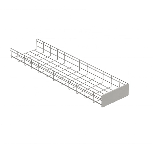
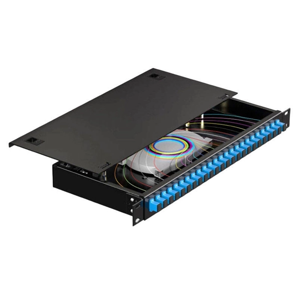
Learn how to install a fiber distribution cabinet step by step, including mounting, cable routing, grounding, and testing for FTTH networks. The installation of a fiber distribution cabinet involves five key steps: site selection, cabinet mounting, cable routing, fiber splicing, and grounding +. This step is very simple, we only need to install brackets on both sides of the optical fiber distribution box, and then fix the brackets to the designated position of the rack with screws. It should be noted that before installing the optical fiber distribution box, the installation direction of. Keeping this page as a placeholder for now. Have any questions? Talk with us directly using LiveChat. Read and understand this procedure (as well as the instructions provided with related assemblies) before beginning an installation. Do not discard this instruction; keep it on hand for future reference. Familiarize yourself to understand the unit's placement in your network. The 1U fiber optic distribution box is used as an example to introduce its structure. Three adapter panels can be installed on the front panel of this fiber optic distribution. Fiber Distribution Hub Installation Procedure - Optical Cable Corporation Products Fiber Copper Hybrid Cabinets, Racks, Enclosures Deployable Solutions Industries Oil & Gas Mining Industrial BroadcastAV Military Commercial Enterprise library & Support Contact Resources About OCC News Careers.
[PDF]
The country has already laid over 4,000 kilometers of fiber optic cables, covering major urban centers and key border crossings. However, the goal is to expand the network to a total of 7,000 kilometers, ensuring nationwide connectivity. The Afghanistan Telecommunications Regulatory Authority. Afghanistan is fast developing into a major trade and transit hub for subsea and transcontinental communication. Once completed, the 4,600 Afghan Fiber Optic Ring (also known as the Afghan National Civil Optical Fiber Cable-OFC ring network) within the broader regional “Digital Silk Road” aims to. Some experts believe fiber optics could serve as a key infrastructure for the growth of Afghanistan's digital economy. Sources have confirmed to TOLOnews that fiber optic internet services have been cut off in Nangarhar province, following earlier shutdowns in Kunduz, Baghlan, Takhar, Badakhshan. GL FIBER & High-Performance Fiber Optic Network Deployment in. Scope: Deployment of a 1,200-km fiber optic backbone network integrating aerial, underground, and submarine routes to enhance national broadband connectivity and support 5G/FTTH rollout. Enayatullah Alokozay, the spokesperson for the ministry, stated that the operations to extend and connect the fiber optic network have.
[PDF]