A common test setup to evaluate Stressed Receiver Sensitivity involves measuring the Optical Modulation Amplitude (OMA) using a square wave, per the standard guidelines. Receiver sensitivity stands as a critical parameter impacting an optical transceiver's functionality. It denotes a module's capability to function in challenging environments and aids network operators in determining the system's maximum reach or link margin. These metrics provide insights into how well your transceivers perform under different conditions, ensuring seamless data transmission. Optical. Whether you're a network engineer validating new inventory or an integrator preparing for deployment, knowing how to test optical transceiver modules can save time, reduce failures, and ensure SLA compliance. Unchecked optical modules can cause: Testing ensures compliance with IEEE 802. 3 and MSA. In optical communication systems, sensitivity is a measure of how weak an input signal can get before the bit-error ratio (BER) exceeds some specified number. The standards body governing the application sets this specified BER. For example, SONET specifies that the BER must be 10 -10 or better. Why Fiber Optic Transceiver Testing is Important? Identify faults and failures: Transceiver testing helps in identifying any faults.
[PDF]
A spectrophotometer is a piece of spectroscopy equipment measures the amount of light absorbed by a sample. This measurement can be useful in many research applications: To identify materials by mapping molecular absorption profiles. To work out solute concentrations in solutions. Specifically, a UV-Visible Spectrometer measures the absorption or transmission of light in the ultraviolet (UV) and visible (Vis) regions of the electromagnetic. A spectrometer is a scientific instrument that analyzes light to reveal information about materials. It functions by separating light into its constituent wavelengths, much like a prism splits sunlight into a rainbow. This analytical capability makes spectrometers valuable tools across many fields. Spectrophotometry is an experimental technique that is used to measure the concentration of solutes in a specific solution by calculating the amount of light absorbed by those solutes. It is widely used in laboratories to analyze various substances, from liquids to gases. Here's a step-by-step guide on how to use a spectrophotometer. When you use spectrophotometry, you gain skills that help in many science fields. This guide makes spectroscopy simple by showing you how to use teaching tools and real experiments. The basic principle is that each compound absorbs or transmits light over a certain range of wavelength. This measurement can.
[PDF]
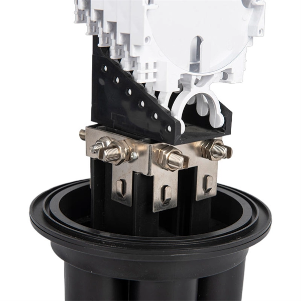
On the US market, a 5. 26 mm 2 (10 AWG) ground wire must be used, and in all other markets a 6 mm 2 must be used. Grounding of the units: Attach a ground wire from one of the threaded studs (A) at the bottom of the housing, to the mounting plate (B). Attach a second grounding wire from the mounting. The correct connection method of Distribution box grounding wire mainly includes the following steps: 1. Find the grounding bar or PE bar Open the distribution box and find the position marked with the grounding plate or PE letter. The basic rule achieves this through an equipment grounding jumper; four exceptions. An equipment grounding conductor passing through the box without a splice is not required to be joined inside the box to others that are spliced in the box. 148 addresses the continuity of equipment grounding conductors and their attachment in boxes. Not all boxes are metal or provide. Correct grounding of services depends upon understanding the definition and role of the grounded conductor. The neutral conductor is typically the grounded conductor connected to the system's neutral point, carrying current under normal operation. Whether you're a seasoned pro or just starting out, this comprehensive guide will give you practical.
[PDF]
To check a fiber connection, connect a jumper to the optical source port and the other end to an optical meter. Press the “test” or “signal” button to send a signal from the source to the meter. In this blog, we'll explore different methods, including using a flashlight, advanced tools like Fluke testers, and more cost-effective options for testing fiber optics. First, we'll show you the. This guide will walk you through diagnosing and resolving common fiber network issues efficiently. Why Do Fiber Networks Fail? Despite their robustness, fiber networks can fail due to: Physical Damage : Cuts, bends, or contamination in fiber cables or connectors. Below is an in-depth guide on how to assess the health and performance of a fiber optic connection: Before relying on technical tools, start. While there are many different fiber optic cable tests, the most common version is an insertion loss test, also known as an attenuation, jumper, or connectivity test. This test requires a special testing kit and protective eyewear, but it will help you diagnose problems with the cable's. We'll explain why it's vital to test fiber optic cables, the three most popular methods, and when you should use them. Related: Fiber Optic Connectors – Identification Guide Regularly testing fiber optic cables helps minimize network downtime, lengthens the network's longevity, reduces maintenance.
[PDF]
National Electrical Code (NEC) allows up to three grounding conductors to terminate under one lug on a grounding bus, provided it is listed for such use. This is covered under section 110. Correct grounding of services depends upon understanding the definition and role of the grounded conductor. The neutral conductor is typically the grounded conductor connected to the system's neutral point, carrying current under normal operation. Grounding electrode conductors must be connected at. Sometimes if I have a 3 or 4-gang plastic nail-on switch box that has a bunch of NM cables, when I'm making up the box rather than using a big blue wire-nut for my grounds I'll separate the grounds into 2 groups and use red/tan wirenuts instead, especially if there's 2 circuits in the box. This configuration may not comply with current electrical. Learn how to connect equipment grounding conductors to receptacles and keep their continuity in boxes. The basic rule achieves this through an equipment grounding jumper; four exceptions. A grounding terminal or grounding-type device on a receptacle, cord connector, or attachment plug may not be used for purposes other than grounding. (b) Branch circuits — (1) Identification of multiwire branch circuits. When conductors are spliced inside a box or terminated to.
[PDF]
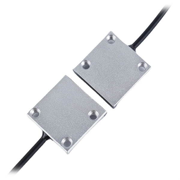
Check the electrical load and ensure that the sensors do not exceed the 10 Amp maximum. Check each wire for damage that may lead to a short. Check the tightness of electrical connections along the power. Understanding how to safely and effectively test a breaker box with a multimeter is a crucial skill for any homeowner or electrician. Regular testing can help identify potential problems, prevent electrical hazards, and ensure the reliable operation of your electrical system. Ignoring this vital. When devices in your new box don't work, you start by testing the circuit. You will want a voltage tester (doesn't need to be a voltmeter) for this job. The very cheapest one you can find at a local hardware store (or online) will work great. In the merger we can see a red wire and a black wire connect the red wire to the megger's line terminal and then. This article summarizes inspection of the building electrical panel, main panel, or electrical distribution and sub panels. A continuity tester is the simplest tool for the specific task of checking for continuity.
[PDF]
The hydraulic wrench head and power pack are connected by a 10,000 psi (68,900 kPa) single-line hose assembly. Each end of the hose will have one female connector. When you install a distribution box, you need a variety of tools to get the job done safely and efficiently. A measuring tape and. Never connect or disconnect any hydraulic hoses or fittings without first unloading the wrench and the pump. Open all hydraulic controls several times to make sure the system has been completely depressurized. If the system includes a gauge, double check the gauge to make sure pressure has been. et that came with your hydraulic t lly inspect all components for shipping damage. If ximum Working Pressure is 10,000 PSI (700 bar). We use baier high pressure hoses to connect the torque wrench and hydraulic pump. Some illustrations in this manual may show details or attachments different from your hoist. Some components have been removed for illustrative purposes. Drawings. Overview The Enerpac S-Series hydraulic torque wrench is designed for controlled tightening and loosening of fasteners in industrial bolting applications. The wrench features a removable square drive shaft that is designed to accept a wide variety of interchangeable hex sockets of different sizes.
[PDF]
This guide breaks down exactly what you are paying for, what a defensible 2026 FOB China price range actually looks like, and how to spot quotes that either undercut reality or overcharge for features you don't need. 💡 Need to vet the supplier behind the quote? Pair this with our PV combiner box. The global market for Photovoltaic DC Distribution Boxes was valued at USD 892. 65 Million in 2025, marking a period of sustained capital appreciation from its 2020 valuation of USD 520. This growth is propelled by increasing renewable energy investment, supportive government policies, and the declining cost of solar panels. A Photovoltaic Distribution Box, also known as a PV distribution box or solar combiner box, is an essential component in a photovoltaic (PV) system that helps manage the electrical connections and distribution of power generated by solar panels. It is usually installed at key locations in photovoltaic power plants to bring together DC power from multiple photovoltaic modules and distribute and control it through. The market for photovoltaic distribution boxes is dynamic and competitive. Selecting the right supplier is critical for system safety, efficiency, and long-term project viability. This guide examines current trends, selection criteria, and key suppliers for this essential B2B component.
[PDF]
In this guide, we will walk you through the process of setting up a network switch, from selecting the right equipment to connecting and testing the network. Ethernet switches, also called network switches, connect multiple devices via Ethernet cables. In contrast, a router connects your local area network (LAN) to the internet's. A practical, current guide to planning, pulling and terminating Cat6/Cat6A cable — tools, techniques, testing and labeling for reliable results. By Thomas McCormack • Updated Mar 17, 2026 • 12 min read • Lead Technician and Engineer, Data Wire Solutions Disclosure: Some links may be affiliate. With an Ethernet cable, you can hardwire your devices to your network, providing fast and efficient. Your ethernet switch doesn't come with any ethernet cables, so you want to have some on hand when setting up your switch. You'll need one cable to connect your ethernet switch and router together (assuming you want to provide your devices with an ethernet connection to the internet), and an. A network switch is a crucial component in any modern network, enabling seamless communication between devices. By the end of this tutorial. Connecting a network switch involves physically connecting devices using Ethernet cables and configuring them as needed, ultimately expanding your network connectivity and improving network performance. Connecting a network switch is a foundational skill for anyone managing a home or small business.
[PDF]
Typical rates range from $75 to $180 per hour per technician, with on-site time often dominating the total. Hidden costs include traffic control, trench restoration, and post-repair verification testing. Prices for fiber optic repair vary by issue type, location, and required work. This guide lays out cost expectations, with clear low–average–high estimates and regional nuances. Includes fusion/splice, testing, and basic materials. This guide provides practical cost ranges in USD with. In the United States, fiber optic repair typically costs a few hundred to several thousand dollars, depending on the scope of the fault, distance of the fiber run, and required components. The cost to fix a fiber line often hinges on the fault type, distance, and response time, with price ranges reflecting differing crews and materials.
[PDF]
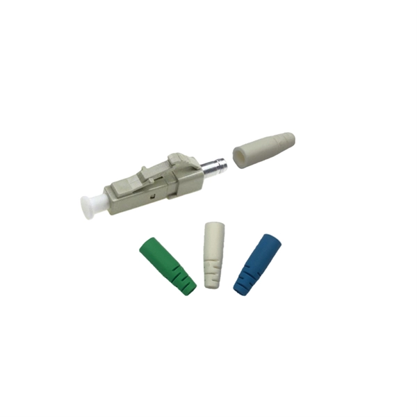
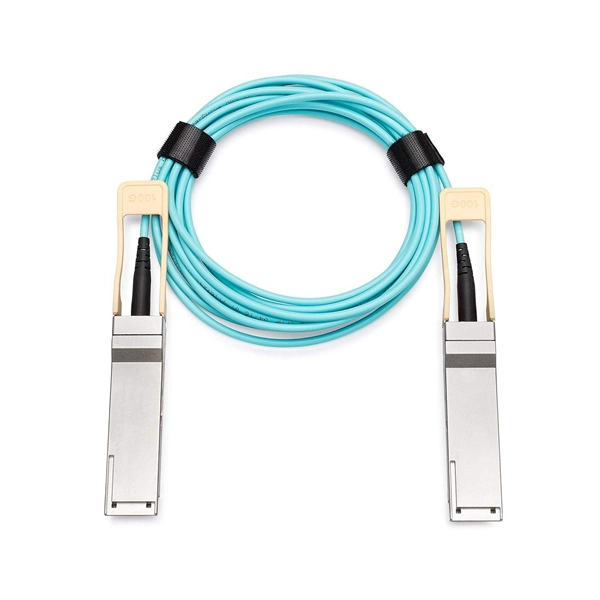
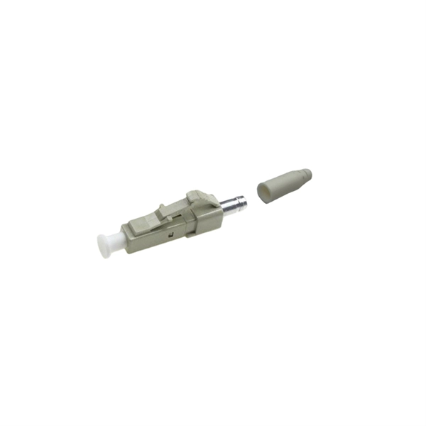
This step-by-step guide aims to provide a comprehensive understanding of the techniques and considerations involved in successfully connecting optical fibers, offering invaluable insights for professionals and enthusiasts in the field. In high-speed data networks, the seamless integration of fiber optic cables with SFP (Small Form-Factor Pluggable) modules is critical for reliable signal transmission. SFP transceivers bridge electrical and optical signals, making them indispensable in data centers, telecom networks, and. Proper connection of fiber optic cables is essential to harness these benefits fully, as even minor errors can lead to significant performance issues like signal loss. This article will guide you through the necessary tools, materials, and methods on how to connect fiber optic cables effectively. This section describes how to install optical transceivers on the SFP or SFP+ ports and connect them to the ports of the peer device using optical fibers according to the network plan. The USG supports both 1 Gbit/s, 10 Gbit/s, and 40 Gbit/s optical modules. The optical modules at both ends are. There are many types of fiber optic connectors, including SC, LC, FC, ST, D4, MU, MT/MPO, etc. These connectors can be divided into single-mode and multi-mode fiber optic connectors according to their structure and purpose. In this tutorial.
[PDF]
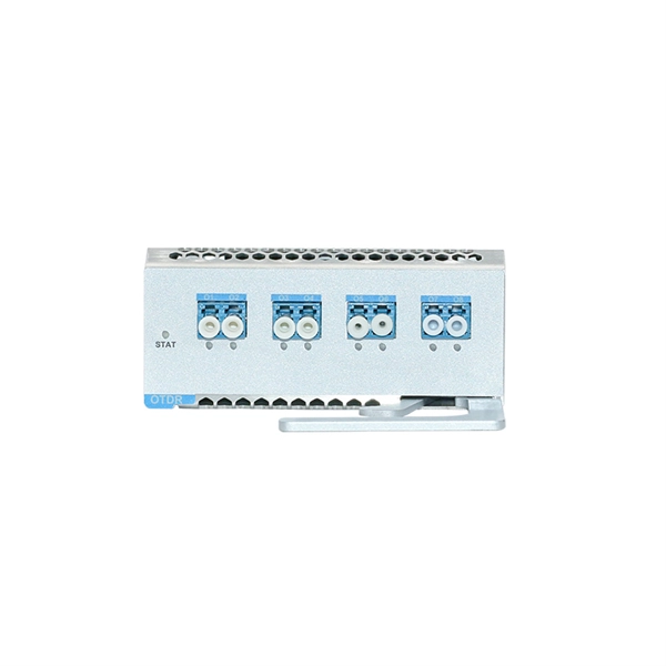
In this Cisco Tech Talk, learn how to view the optical module status on a Cisco switch using the Command Line Interface (CLI). This video demonstrates how to access the optical module status, check for any issues, and monitor the health of your network's optical components. Learn. When optical modules operate on a switch, it is usually necessary to read the module's internal information to understand its working status—such as connection status and real-time metrics like optical power and temperature. Additionally, identifying module information helps detect coding. This chapter describes how to configure the Optical Amplifier Module and Protection Switching Module (PSM). When you plan to replace a configured optical module with a different type of optical module, you must clear the configurations of the old module before you install the new module. By checking module health, compatibility, and digital diagnostics, you can quickly confirm correct installation, detect optical problems, and maintain accurate hardware. Small Form-factor Pluggable modules (SFP module) are the workhorses of modern network connectivity, enabling flexible fiber optic or copper links between switches, routers, firewalls, and servers. Whether you're upgrading bandwidth, replacing a faulty unit, or reconfiguring your topology, knowing.
[PDF]
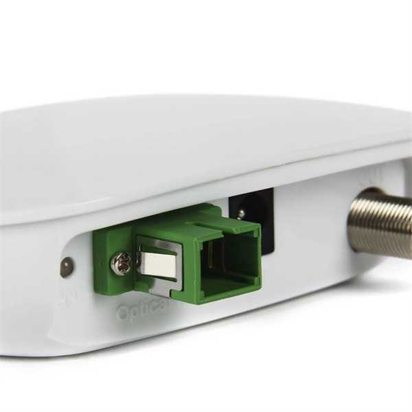
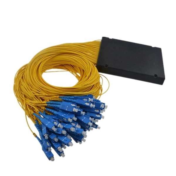
A 4-core fiber optic cable is a type of cable that contains four individual optical fibers within a single protective jacket. These fibers are used to transmit data as light signals, offering high-speed data transfer capabilities over long distances with minimal loss. This guide covers everything you need to know about 4 core fiber, including its internal structure, TIA standard color coding, and how to choose the right type. They are used to connect final user to FTTH or GPON line. Jera is a direct manufacturer who supply a wide range product for. This cable can be used for LAN and WAN backbones, telecom access lines, fibre to business and fibre to the building or the homme connections. It is equally suited for installation in ducts and on trays. This cable features a 0. 15mm corrugated steel armour which makes it rodent proof. OM3 and higher. A TOSLINK optical fiber cable with a clear jacket. What is a 4 Core Optical Cable? A 4 Core Optical Cable is a fiber optic cable that contains four individual optical fibers within a single. Unlike copper wires, which are limited by lower data transmission speeds, shorter transmission distances, and higher susceptibility to electromagnetic interference, fiber optic cables offer unparalleled performance and can cover much greater distances without bumping up against signal degradation.
[PDF]
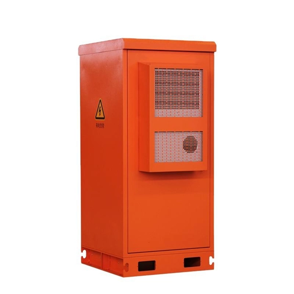
A neat, well-organized subpanel bundles wires to conserve space and improve access. Ideally, wire groups are installed in layers and wires are bent at right angles to buses or breakers. Label short sheathing sections (slugs) to indicate which circuits wires serve. Choose the right box based on environment (indoor/outdoor), load capacity, and durability. Check for proper IP/NEMA ratings and material quality. Ensure safe placement: install in dry, accessible areas with good ventilation and at appropriate height (typically ~1. Practice good wiring: secure. Box installation: Make sure that Distribution box has been correctly installed and fixed. Material preparation: Prepare the required circuit breakers, wires, wiring ties and other materials, and ensure that they meet the design drawings and installation requirements. And all the switching and protective devices are installed in the. Wiring distribution panels serve as the central hub and nerve center, routing power from the main service feed to multiple circuits. When setting up such a significant component of industrial, commercial, and utility applications, it's essential to get everything right. Labeling cables at outlets is.
[PDF]
Converting multimode fiber to single-mode fiber can improve network performance and future-proof infrastructure. This guide will walk you through the methods, challenges, and best practices for successfully converting multimode to . This guide will break down the professional methods to achieve seamless single-mode to multi-mode conversion, ensuring your network integrity and performance. 📝 Why Can't You Directly Connect SMF and MMF? At its heart, the incompatibility is physical. The core size of multi-mode fiber is. How can we convert the multimode to a singlemode fiber system? This complete guide will provide answers to these questions. Mode conversion is typically required when: FlexPoint unmanaged Fiber-to-Fiber Media Converters provide multimode to single-mode conversion, and support a variety of network. Fiber mode conversion, especially multimode to single-mode fiber conversion (MMF-to-SMF conversion) is required when the distance is an important parameter to consider in optical applications. In this tutorial, three methods will be introduced to support mode conversion from multimode to. Multimode fiber (MMF) and single-mode fiber (SMF) are two types of fiber optic cables utilized for transmitting light signals over extended distances (For details, please refer to the blog post “ Choosing the Right Fiber Optic Cable: Singlemode vs Multimode “). The primary distinction between them.
[PDF]