This video shows real on-site footage of electrical installation, demonstrating safe and standardized wiring methods used by professionals. more Learn how to wire a distribution box step by step!. A distribution box, also known as an electrical distribution board, is a critical component in electrical systems. It serves as a central point for distributing electricity to various circuits in a building or facility. It has three categories: residential, commercial and industrial electrical distribution boxes, all of which play important roles in their respective electrical. In modern electrical systems, cable distribution boxes (also known as electrical distribution boxes or distribution boxes) play a crucial role as the key hub for managing, distributing, and protecting circuits. What is the role of the electrical panel? It's also called the breaker box or distribution board. It's the central hub that divides main service lines into smaller branch.
[PDF]
This video shows real on-site footage of electrical installation, demonstrating safe and standardized wiring methods used by professionals. more Learn how to wire a distribution box step by step! This video shows real on-site footage of. A ddc panel wiring diagram provides a visual representation of the connections and wiring between the ddc panel and other components in the building automation system. It includes information about the various input and output points, the power supply, and the communication channels. A. A distribution box is the heart of any electrical system. It takes the incoming power and safely distributes it to different circuits throughout your building. Whether in a home or an industrial facility, this box keeps your electrical setup organized, functional, and efficient. This section will explain its function, types, and the importance of correct. A facility's direct digital controls (DDCs) form a living, breathing system that an owner will use throughout the life of the building. However, many control systems do not work as designed on “Day One,” much less after two to three years of use. Adding to the complexity are subcontractors, who. Strictly speaking, the word “Distribution Box (D-box)” can refer to two categories: electrical distribution boxes and septic tank distribution boxes. This article mainly talks about the first one. An electrical distribution box, also known as a power distribution box, panelboard, or consumer unit.
[PDF]
In this video, we'll walk you through the process of wiring a home distribution box with a detailed connection diagram. Whether you're an electrician or a DIY enthusiast, this guide will help you understand the basics of home electrical distribution. more Welcome to our channel! In this video. A distribution board or distribution box is where the main power supply is distributed to multiple loads. And all the switching and protective devices are installed in the distribution box. Single Phase Distribution Box generally consists of Double Pole MCBs, Single Pole MCBs, and RCCBs. Single Phase wiring installation is the most common wiring in residential buildings. It is essential for managing the electrical supply to various appliances and circuits in the building. Its function is to safely divide the incoming high-amperage utility power into smaller, manageable branch circuits that supply power to lights, outlets, and.
[PDF]
This post is a step-by-step detailed installation guide on how to run wires for security cameras to help you install security camera wiring for both indoors and outdoors. Proper wiring is crucial to ensuring that your security cameras function effectively and provide clear, uninterrupted footage. How to connect your cameras and recorder to provide power and a video feed, including for remote viewing via smartphones and computers. We always recommend wired systems when possible. We offer two different types of wired security camera systems -. There are two different ways to install security camera wiring: POE security camera wiring and wireless security camera wiring. Whether you're securing your home or business, the quality and installation of your camera wiring play a crucial role in ensuring consistent, high-quality video feeds. In this guide, we. This article provides a detailed principle explanation of 3R methods (reamplification, reshaping, and retiming) to reach the extension of passive optical networks. The second part of the article focuses on optical amplifiers, their advantages and disadvantages, deployment, and principles. We. In this step-by-step guide, we will walk you through the process of wiring your 2 wire security camera, providing you with a clear understanding of the necessary steps and a helpful diagram to refer to.
[PDF]
This video goes over common types of connectors, their respective adapters, and how to properly connect and disconnect them. For your safety, it is always advised to follow proper fiber optic handling techniques and utilize the correct protective gear when performing. Fiber optic adapters, also known as couplers, play a crucial role in fiber optic networks by providing a connection point between two fiber optic connectors. They enable seamless and reliable optical signal transmission between different fiber optic cables, connectors, or devices. In this tutorial. Proper connection of fiber optic cables is essential to harness these benefits fully, as even minor errors can lead to significant performance issues like signal loss. more Are you interested in seeing how fiber optic connectors get. Vigitron's Vi5004 is a 4-port fiber optic media convertor that enables Ethernet signals to be transmitted over fiber optic cables. It enable UTP Ethernet to connect to fiber to meet long distance transmission requirement or where fiber is already installed. Why Use Fiber Optic Internet? Before diving into the setup, let's quickly recap why fiber optics are worth the effort: Lightning-fast speeds (up to 1 Gbps or higher). Low latency for.
[PDF]
In this video, we'll walk you through the process of wiring a home distribution box with a detailed connection diagram. Whether you're an electrician or a DIY enthusiast, this guide will help you understand the basics of home electrical distribution. more Welcome to our channel! In this video. Understanding the wiring diagram of an electrical panel box is essential for electricians and homeowners alike, as it allows them to troubleshoot any electrical issues, carry out repairs, or make additions to the system. The electrical panel box wiring diagram provides a visual representation of. A distribution board or distribution box is where the main power supply is distributed to multiple loads. And all the switching and protective devices are installed in the distribution box. Single Phase Distribution Box generally consists of Double Pole MCBs, Single Pole MCBs, and RCCBs. Connect the two hot conductors (typically black and red) to the line terminals of the main disconnect switch. Tighten each lug to 250 inch-pounds using a torque wrench. What is Distribution Board? Distribution board.
[PDF]
This video shows real on-site footage of electrical installation, demonstrating safe and standardized wiring methods used by professionals. A distribution board, also known as a DB box, is like the central hub of an electrical system. It contains multiple circuit breakers and connects various electrical circuits to ensure. Box installation: Make sure that Distribution box has been correctly installed and fixed. Material preparation: Prepare the required circuit breakers, wires, wiring ties and other materials, and ensure that they meet the design drawings and installation requirements. It serves as a central hub for distributing electricity throughout a building, ensuring that power is delivered safely and efficiently to all the required locations. It takes the incoming power and safely distributes it to different circuits throughout your building. Whether in a home or an industrial facility, this box keeps your electrical setup organized, functional, and efficient. It has three categories: residential, commercial and industrial electrical distribution boxes, all of which play important roles in their respective electrical.
[PDF]
In this video, we'll walk you through the process of wiring a home distribution box with a detailed connection diagram. Whether you're an electrician or a DIY enthusiast, this guide will help you understand the basics of home electrical distribution. more Welcome to our channel! In this video. A distribution box is the heart of any electrical system. It takes the incoming power and safely distributes it to different circuits throughout your building. However, the key to. In this article, we'll explain how to install a weatherproof electrical box, from selecting the right materials to properly securing the box in place. Weatherproof electrical boxes are designed to handle extreme weather conditions, such as heavy rain and strong winds. They're also designed to. Whether you're a do-it-yourselfer, the neighborhood handyman, or a professional electrician, knowing how to properly install a weatherproof electrical junction box can save time, and your system components will continueto operate for years. Standard indoor electrical boxes are not designed to handle exposure to rain, snow, or high humidity, which can quickly lead to corrosion. Whether adding a GFCI outlet for safety or upgrading an exterior outlet for weather-resistant durability, it's essential to follow proper electrical wiring guidelines to ensure compliance with local codes and prevent hazards. This guide explains the different types of outdoor electrical boxes.
[PDF]
Trim solid or stranded wire to length and insert into clamp-style terminals. Tighten with a screwdriver. Tug on all connections to make sure they are secure. Close up electrical boxes. Turn on the power and check your work. Learn how to wire a distribution box step by step! This video shows real on-site footage of electrical installation, demonstrating safe and standardized wiring methods used by professionals. Make sure the power's off using a non-contact voltage tester or multimeter. One final tip: Get into the habit of making connections in this. This guide provides step-by-step instructions for connecting a distribution box and highlights key factors to consider during installation. What Is a Distribution Box? A distribution box, also known as an electrical distribution board, is a critical component in electrical systems. It serves as a. Material preparation: Prepare the required circuit breakers, wires, wiring ties and other materials, and ensure that they meet the design drawings and installation requirements. Choose the right box based on environment (indoor/outdoor), load capacity, and durability. Check for proper IP/NEMA ratings and material quality. Beginning of dialog window. Escape will cancel and close the window. This modal can be closed by pressing the Escape key or activating the close button.
[PDF]
In this guide, we will walk you through the process of setting up a network switch, from selecting the right equipment to connecting and testing the network. Ethernet switches, also called network switches, connect multiple devices via Ethernet cables. In contrast, a router connects your local area network (LAN) to the internet's. A practical, current guide to planning, pulling and terminating Cat6/Cat6A cable — tools, techniques, testing and labeling for reliable results. By Thomas McCormack • Updated Mar 17, 2026 • 12 min read • Lead Technician and Engineer, Data Wire Solutions Disclosure: Some links may be affiliate. With an Ethernet cable, you can hardwire your devices to your network, providing fast and efficient. Your ethernet switch doesn't come with any ethernet cables, so you want to have some on hand when setting up your switch. You'll need one cable to connect your ethernet switch and router together (assuming you want to provide your devices with an ethernet connection to the internet), and an. A network switch is a crucial component in any modern network, enabling seamless communication between devices. By the end of this tutorial. Connecting a network switch involves physically connecting devices using Ethernet cables and configuring them as needed, ultimately expanding your network connectivity and improving network performance. Connecting a network switch is a foundational skill for anyone managing a home or small business.
[PDF]
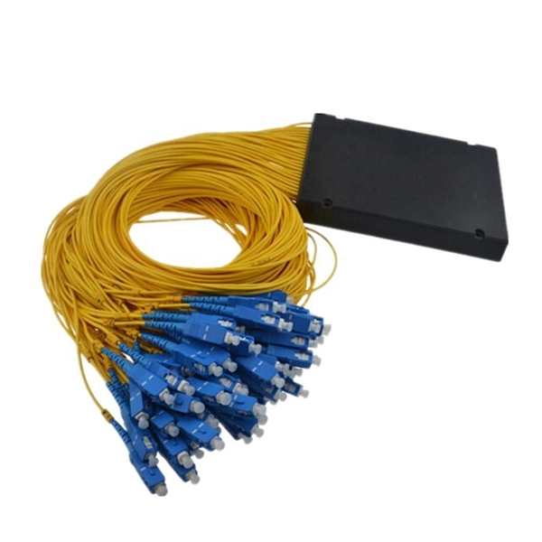
This step-by-step guide aims to provide a comprehensive understanding of the techniques and considerations involved in successfully connecting optical fibers, offering invaluable insights for professionals and enthusiasts in the field. In high-speed data networks, the seamless integration of fiber optic cables with SFP (Small Form-Factor Pluggable) modules is critical for reliable signal transmission. SFP transceivers bridge electrical and optical signals, making them indispensable in data centers, telecom networks, and. Proper connection of fiber optic cables is essential to harness these benefits fully, as even minor errors can lead to significant performance issues like signal loss. This article will guide you through the necessary tools, materials, and methods on how to connect fiber optic cables effectively. This section describes how to install optical transceivers on the SFP or SFP+ ports and connect them to the ports of the peer device using optical fibers according to the network plan. The USG supports both 1 Gbit/s, 10 Gbit/s, and 40 Gbit/s optical modules. The optical modules at both ends are. There are many types of fiber optic connectors, including SC, LC, FC, ST, D4, MU, MT/MPO, etc. These connectors can be divided into single-mode and multi-mode fiber optic connectors according to their structure and purpose. In this tutorial.
[PDF]
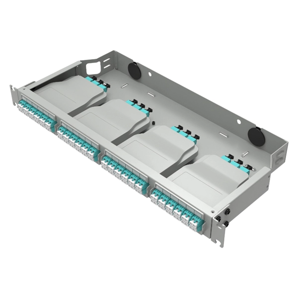
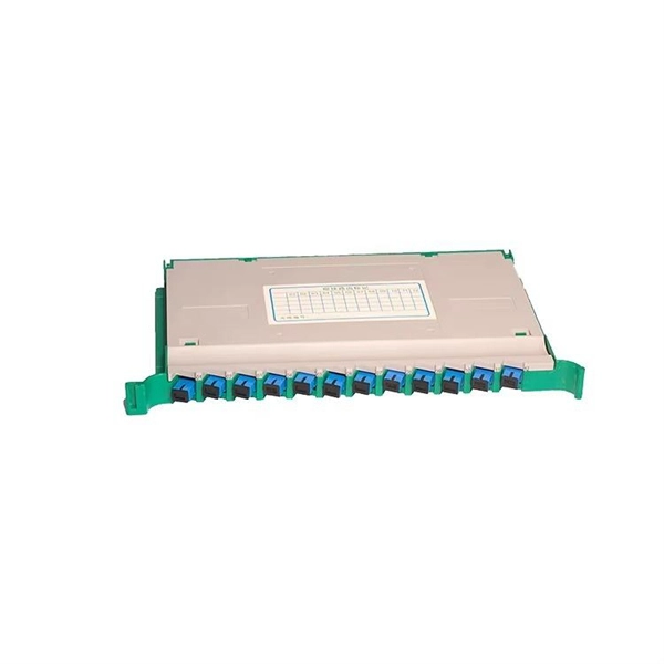
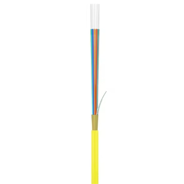
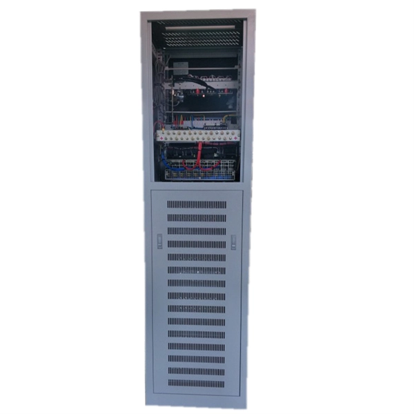
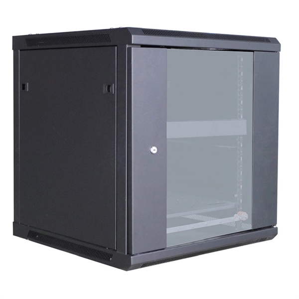
Learn how to install a fiber distribution cabinet step by step, including mounting, cable routing, grounding, and testing for FTTH networks. The installation of a fiber distribution cabinet involves five key steps: site selection, cabinet mounting, cable routing, fiber splicing, and grounding +. This step is very simple, we only need to install brackets on both sides of the optical fiber distribution box, and then fix the brackets to the designated position of the rack with screws. It should be noted that before installing the optical fiber distribution box, the installation direction of. Keeping this page as a placeholder for now. Have any questions? Talk with us directly using LiveChat. Read and understand this procedure (as well as the instructions provided with related assemblies) before beginning an installation. Do not discard this instruction; keep it on hand for future reference. Familiarize yourself to understand the unit's placement in your network. The 1U fiber optic distribution box is used as an example to introduce its structure. Three adapter panels can be installed on the front panel of this fiber optic distribution. Fiber Distribution Hub Installation Procedure - Optical Cable Corporation Products Fiber Copper Hybrid Cabinets, Racks, Enclosures Deployable Solutions Industries Oil & Gas Mining Industrial BroadcastAV Military Commercial Enterprise library & Support Contact Resources About OCC News Careers.
[PDF]
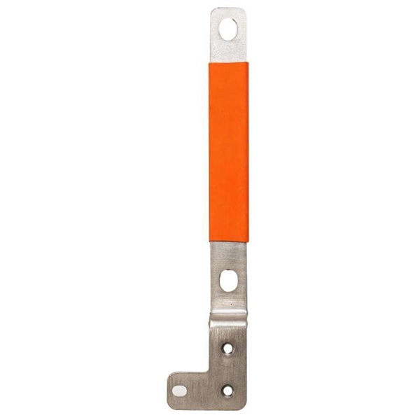
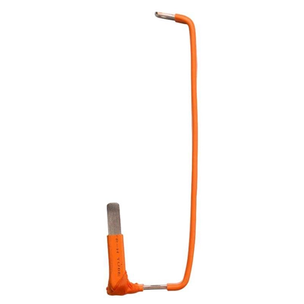
Calm the chaos by following clear current, temperature, and clearance rules from IEC 61439 guidelines and this handy overview from ABB's busbar selection guide: ABB Busbar Applications Handbook. In the power transmission and distribution system, busbar is the core conductive component, which is widely used in high-voltage transmission, data center, new energy, rail transportation, industrial automation and other fields. Different types of busbars have their own characteristics in terms of. Prices of bus bar assemblies vary depending upon quantity ordered. In addition, individual dimensional characteristics, materials, manufacturing techniques, the interconnection scheme, plating finish, insulation, and hardware requirements affect overall cost. Busbars act as the main current highways inside high voltage switchboards, linking incoming feeders. When designing electrical power systems, one of the most critical aspects is selecting the right size for busbars. Busbars are the backbone of switchboards, distribution boards, and electrical panels. The group of busbars are consisting of 5 bars, one for each phase, one for neutral and one. To connect various high voltage (HV) components to the HV system, TE also delivers a wide variety of busbars. In cooperation with the customer, these can also feature TE's Bus Bar Insulation Tubing (BBIT). Busbars provide a safe HV connection on shorter distances. Especially in the area near the.
[PDF]
It receives power from the main electrical supply and divides it into separate circuits, each protected by circuit breakers or fuses. The primary purpose of a distribution box is to provide a safe and organized way to control electrical circuits. In this guide, we'll break down the 12 main types of distribution boxes in a way that's easy to understand. We'll chat about what each one does, where it shines, and then dive into how to choose the perfect box for your needs. Plus, we'll sprinkle in some practical tips to make sure you're not. A distribution box, also known as a power distribution box or electrical distribution box, is used to distribute electrical power safely to multiple circuits. It helps organize, protect, and control electrical connections in residential, commercial, and industrial electrical systems. It acts like a hub or traffic controller, managing power flow to different areas or devices. What is the distribution box? A. Electrical systems power our homes, offices, and industrial facilities, but behind every reliable electrical setup lies a crucial component that often goes unnoticed: the distribution box. This essential piece of equipment serves as the nerve center of your electrical system, managing power flow.
[PDF]
Use this worksheet to input values for all variables that will impact your system's performance. After entering your values, please ensure you click the 'Calculate Link Loss' button at the bottom of the page to generate your total link loss. Add connectors, splices, bends, and safety margin easily. See results instantly above the form, then adjust values. Choose a mode, then enter values and optional losses. All calculations use base-10 logarithms. mW must be greater than zero. Used only in measured attenuation mode. Length is needed. The power budget refers to the amount of fiber optic cable plant loss that a datalink (transmitter to receiver) can tolerate in order to operate properly. Sometimes the power budget has both a minimum and maximum value, which means it needs at least a minimum value of loss so that it does not. To detect whether the link runs properly, the following calculation should be performed. It is often the case to calculate the maximum signal loss across a given fiber link during optical cable installation. First, you should be aware of the fiber loss formula: The Total Link Loss = Cable. Therefore, it is very important to calculate the fiber loss and take appropriate steps. In order to get the most reliable results, an Optical Time Domain Reflectometer (OTDR) trace of the actual fiber connection should be completed. This will provide you with the real.
[PDF]