This guide reveals the secrets to fusion splicing with little fluff—just proven, straightforward techniques refined from years of work in the field. In this guide, you will find a chronological description of the fusion splicing process, the principal technical standards, and answers to the real-life questions network engineers and procurement teams may have. The guide provides the complete workflow, covering safety precautions, tool selection, fiber preparation, fusion operation, quality control, and. Summary: Fiber color codes, defined by the TIA-598-C standard, help technicians quickly identify individual fibers, buffer tubes, and connectors in multi-strand cables. Using proper color coding makes installation easier, speeds up troubleshooting, reduces downtime, and supports future network. When a tech opens a fiber optic cable to prepare it for splicing, they will find a colorful bundle of buffer tubes as on this armored cable. The colors of the buffer tubes and likewise the fibers in the tubes provide the identification the tech needs to complete the splicing of the fibers as the. Fusion splicing is the bedrock of high-performance fiber optic networks, enabling seamless signal transmission through permanent, low-loss fiber joins. By adopting the TIA/EIA‑598C standard, you gain a universal “language” of colors that speeds identification, reduces miswiring, and enhances safety.
[PDF]
This guide covers everything: what fiber optic pigtails are, how they differ from patch cords, which connector and polish type to specify, how to choose between mechanical and fusion splicing, and the real-world applications where pigtails are the right call. This article compares fusion splicing and pre-terminated solutions on these terms, and reviews what's required in a hyperscale ODF in order to scale up to 5,000+ connections in a single frame. Fusion splicing vs connectorization: what's the best choice for a hyperscale ODF? The physics and. Fiber optic joints or terminations are made two ways: 1) splices which create a permanent joint between the two fibers or 2) connectors that mate two fibers to create a temporary joint and/or connect the fiber to a piece of network gear. Either joining method must have three primary characteristics. There are two primary techniques for terminating fiber optic cables: Splicing: Joining two fiber optic cables permanently. Connectors: Attaching removable connectors for quick and flexible connections. Fiber splicing is the process of permanently joining two optical fibers end-to-end. This blog will delve into the nuances of each method, comparing their costs, labor efficiency, network performance, and more, to help you decide which splicing technique is best suited for your needs. Fusion splicing involves heating the fiber ends and fusing them together, while mechanical splicing uses tubes, V-grooves, or other guides to.
[PDF]
You simply multiply the number of splices by the estimated loss per splice. It's that easy! ✨ Let's say you have a long fiber run that requires 4 fusion splices to connect different cable segments. 4 dB is the total attenuation you'll add to your loss budget just for the. Fusion splicing is the process of fusing or welding two fibers together usually by an electric arc. Fusion splicing is the most widely used method of splicing as it provides for the lowest loss and least reflectance, as well as providing the strongest and most reliable joint between two fibers. There are several ways to know the number of multi-spliced cores. For example, 12 core fibers, 12*2=24 cores, 12 cores at the beginning and 12 cores at the end; 2. Count the number of optical fiber. Calculating the total loss from splices in a cable run is wonderfully straightforward. Connectors: Total number of connectors in design. Laser: A device which produces a single frequency light. The guide provides the complete workflow, covering safety precautions, tool selection, fiber preparation, fusion operation, quality control, and. Recommendation ITU-T L. 12 specifies splices of single-mode and multimode optical fibres. It describes suitable procedures for splicing that should be carefully followed in order to obtain reliable splices between single optical fibres or ribbons.
[PDF]
The country has already laid over 4,000 kilometers of fiber optic cables, covering major urban centers and key border crossings. However, the goal is to expand the network to a total of 7,000 kilometers, ensuring nationwide connectivity. The Afghanistan Telecommunications Regulatory Authority. Afghanistan is fast developing into a major trade and transit hub for subsea and transcontinental communication. Once completed, the 4,600 Afghan Fiber Optic Ring (also known as the Afghan National Civil Optical Fiber Cable-OFC ring network) within the broader regional “Digital Silk Road” aims to. Some experts believe fiber optics could serve as a key infrastructure for the growth of Afghanistan's digital economy. Sources have confirmed to TOLOnews that fiber optic internet services have been cut off in Nangarhar province, following earlier shutdowns in Kunduz, Baghlan, Takhar, Badakhshan. GL FIBER & High-Performance Fiber Optic Network Deployment in. Scope: Deployment of a 1,200-km fiber optic backbone network integrating aerial, underground, and submarine routes to enhance national broadband connectivity and support 5G/FTTH rollout. Enayatullah Alokozay, the spokesperson for the ministry, stated that the operations to extend and connect the fiber optic network have.
[PDF]
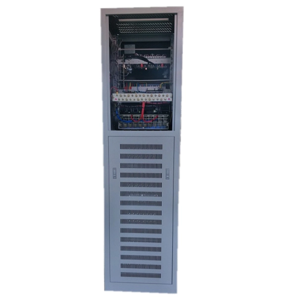
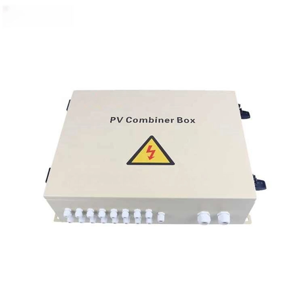
It receives power from the main electrical supply and divides it into separate circuits, each protected by circuit breakers or fuses. The primary purpose of a distribution box is to provide a safe and organized way to control electrical circuits. In this guide, we'll break down the 12 main types of distribution boxes in a way that's easy to understand. We'll chat about what each one does, where it shines, and then dive into how to choose the perfect box for your needs. Plus, we'll sprinkle in some practical tips to make sure you're not. A distribution box, also known as a power distribution box or electrical distribution box, is used to distribute electrical power safely to multiple circuits. It helps organize, protect, and control electrical connections in residential, commercial, and industrial electrical systems. It acts like a hub or traffic controller, managing power flow to different areas or devices. What is the distribution box? A. Electrical systems power our homes, offices, and industrial facilities, but behind every reliable electrical setup lies a crucial component that often goes unnoticed: the distribution box. This essential piece of equipment serves as the nerve center of your electrical system, managing power flow.
[PDF]
Use this worksheet to input values for all variables that will impact your system's performance. After entering your values, please ensure you click the 'Calculate Link Loss' button at the bottom of the page to generate your total link loss. Add connectors, splices, bends, and safety margin easily. See results instantly above the form, then adjust values. Choose a mode, then enter values and optional losses. All calculations use base-10 logarithms. mW must be greater than zero. Used only in measured attenuation mode. Length is needed. The power budget refers to the amount of fiber optic cable plant loss that a datalink (transmitter to receiver) can tolerate in order to operate properly. Sometimes the power budget has both a minimum and maximum value, which means it needs at least a minimum value of loss so that it does not. To detect whether the link runs properly, the following calculation should be performed. It is often the case to calculate the maximum signal loss across a given fiber link during optical cable installation. First, you should be aware of the fiber loss formula: The Total Link Loss = Cable. Therefore, it is very important to calculate the fiber loss and take appropriate steps. In order to get the most reliable results, an Optical Time Domain Reflectometer (OTDR) trace of the actual fiber connection should be completed. This will provide you with the real.
[PDF]
In this video, we'll walk you through the process of wiring a home distribution box with a detailed connection diagram. Whether you're an electrician or a DIY enthusiast, this guide will help you understand the basics of home electrical distribution. more Welcome to our channel! In this video. Understanding the wiring diagram of an electrical panel box is essential for electricians and homeowners alike, as it allows them to troubleshoot any electrical issues, carry out repairs, or make additions to the system. The electrical panel box wiring diagram provides a visual representation of. A distribution board or distribution box is where the main power supply is distributed to multiple loads. And all the switching and protective devices are installed in the distribution box. Single Phase Distribution Box generally consists of Double Pole MCBs, Single Pole MCBs, and RCCBs. Connect the two hot conductors (typically black and red) to the line terminals of the main disconnect switch. Tighten each lug to 250 inch-pounds using a torque wrench. What is Distribution Board? Distribution board.
[PDF]
The process involves a combination of national infrastructure, local engineering, and property-level setup. In this guide, we'll break down the fiber installation process from start to finish and explain key components such as fiber cabinets, flower pods, ducting, and ONT setup. This guide walks you through the complete fiber installation process, from checking availability to optimizing your Wi-Fi network performance. Once you understand the basic concepts, you can check out my Recommended Equipment section toward the bottom of the. In this article we'll break down how fiber internet is installed - from the network fiber drop outside your house to the in-home setup with your router and gateway - and what you should expect at each stage. Fiber optic internet is generally installed in the following 5 steps, which we'll dive. Setting up a fiber optic network requires careful planning and execution. Introduction Installing a fiber optic network can seem daunting, but with the right. Usually setting up fiber internet requires a professional installation, but there are some parts of the process you can do yourself. For those taking their first steps into the world of fiber-optic internet—or those who are still considering it—here's all you need to know. Jump to: How to.
[PDF]
The fastest way to test a fluorescent tube is with a multimeter set to continuity mode. Each end of the tube has two pins connected by a thin filament inside the glass. If either filament is broken, the tube is dead. The whole test takes about 30 seconds per tube once you know what. Knowing how to use a multimeter to check an LED tube light is a valuable skill for homeowners, electricians, and anyone involved in maintaining lighting systems. Perhaps it's a simple wiring problem, a. One essential tool for diagnosing LED tube light issues is a multimeter. This process measures electrical resistance to determine if the tube has suffered an internal failure before replacing the bulb or investigating the ballast. If you don't have a multimeter to use, a simple coin cell battery holder with leads will let you know. Yes, you absolutely can test an LED light with a multimeter! It's a straightforward process that helps you figure out if your LED is working or if it's the source of a problem in your circuit.
[PDF]
Converting multimode fiber to single-mode fiber can improve network performance and future-proof infrastructure. This guide will walk you through the methods, challenges, and best practices for successfully converting multimode to . This guide will break down the professional methods to achieve seamless single-mode to multi-mode conversion, ensuring your network integrity and performance. 📝 Why Can't You Directly Connect SMF and MMF? At its heart, the incompatibility is physical. The core size of multi-mode fiber is. How can we convert the multimode to a singlemode fiber system? This complete guide will provide answers to these questions. Mode conversion is typically required when: FlexPoint unmanaged Fiber-to-Fiber Media Converters provide multimode to single-mode conversion, and support a variety of network. Fiber mode conversion, especially multimode to single-mode fiber conversion (MMF-to-SMF conversion) is required when the distance is an important parameter to consider in optical applications. In this tutorial, three methods will be introduced to support mode conversion from multimode to. Multimode fiber (MMF) and single-mode fiber (SMF) are two types of fiber optic cables utilized for transmitting light signals over extended distances (For details, please refer to the blog post “ Choosing the Right Fiber Optic Cable: Singlemode vs Multimode “). The primary distinction between them.
[PDF]
Main cost drivers include cable grade (indoor vs outdoor, armoured), distance, and labor for trenching, splicing, and termination. This guide presents ranges in USD and practical price estimates to help budget planning. Indoor OM3/OM4 vs outdoor armoured increases price. This guide outlines the major factors that influence fiber optic cable costs and provides practical tips for estimating pricing in bulk or project-based scenarios. Content 1 What's the Typical Price Range? 2 1. Fiber Count and Cable Construction 3 2. Fiber-optic cable materials typically cost $1 to $6 per linear foot, depending on fiber count and cable type. Commercial building installations with 100-200 network drops generally range from $15,000 to $30,000. Single-mode fiber costs less per foot than multimode fiber, but it requires more. Buyers typically pay for fiber optic cable by length, fiber type, and installation complexity. Fiber. The fiber optic cable protection tube market was valued at $1. 8 billion in 2023 and is expected to exceed $2. 1 mm diameter, containing 90 fire-resistant, flexible, and robust conduits.
[PDF]
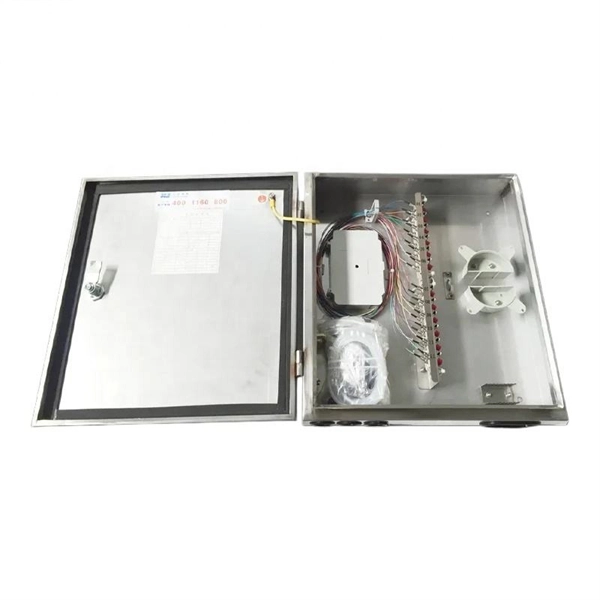
Fiber splice closures are not used occasionally — they are deployed extensively across every fiber network. The exact quantity depends on population density, network topology, and regional infrastructure planning. There are hundreds of different designs and options on splice closures. Some are designed for concatenation of long distance cables where two identical cables are spliced together. Its role is not only to enclose the splice, but to ensure that optical performance remains stable throughout years of operation. In FTTX and outdoor access networks especially, the reliability of. There are several types of fiber optic splice closures available in the market, each designed for specific applications and environments. There are many possible ways to put two or more cables together or drop a single fiber at a location. It creates an air-tight environment that safeguards these splices from environmental considerations, including wetness, dust, and temperature changes; hence, the. CommScope addresses these challenges with a comprehensive family of fiber splice closures that prioritize essential criteria: reliability, installability, flexibility, and speed of deployment. Trunk and Feeder Network Solutions: These closures are designed for robust performance in the backbone of.
[PDF]

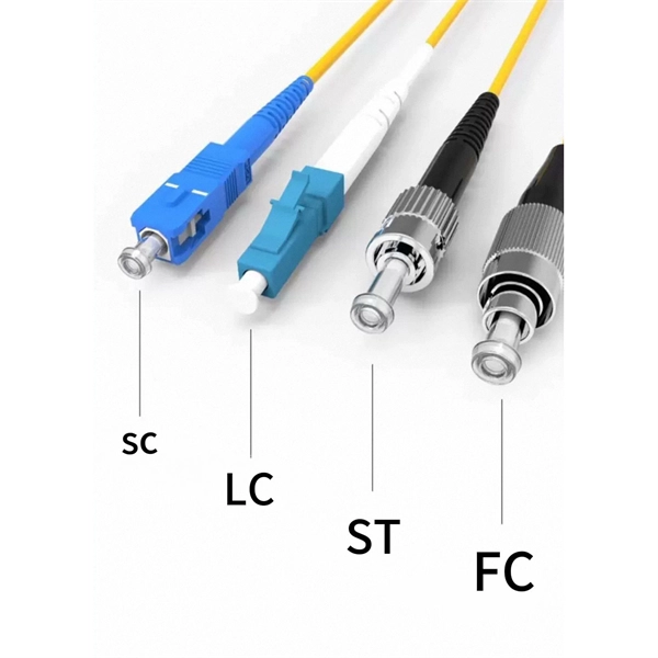
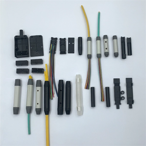
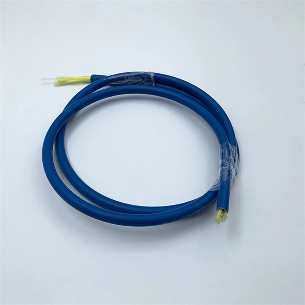
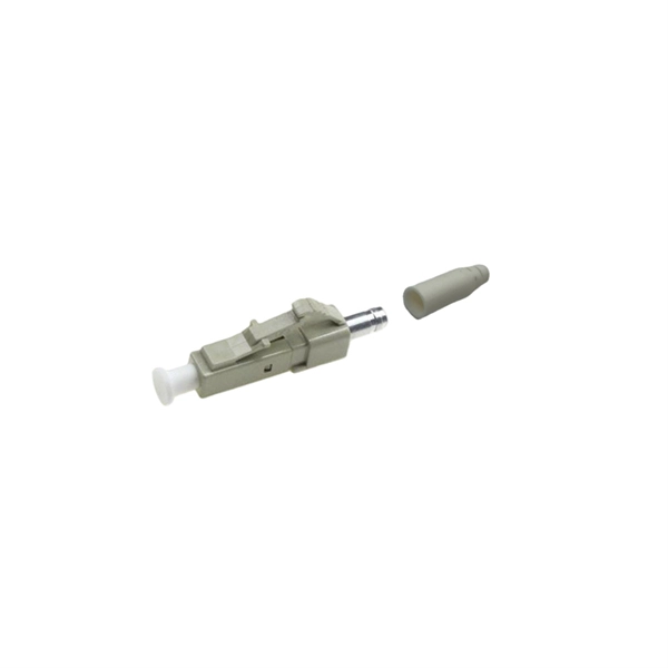
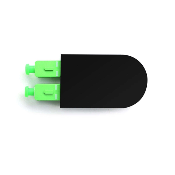
In this guide, we'll walk you through the entire process of preparing fiber optic cable for splicing and termination to fiber connectors. We'll explore the necessary tools, safety precautions, and step-by-step procedures for cable connectors, mechanical and. This article will guide you through the necessary tools, materials, and methods on how to connect fiber optic cables effectively, ensuring you achieve optimal performance from your fiber optic network. Have a network installation project? Fiber Optic Cables: The primary medium for your connections. There are many types of fiber optic connectors, including SC, LC, FC, ST, D4, MU, MT/MPO, etc. These connectors can be divided into single-mode and multi-mode fiber optic connectors according to their structure and purpose. Fiber optic connectors play an essential role in the realm of optical communication, enabling seamless connections between fiber optic cables. At the heart of any robust fiber optic network lies a crucial process: Preparing a fiber cable for termination of a connector or splice. Whether you're installing a new network, expanding an existing one, or. Fiber optic internet delivers blazing-fast speeds and reliable connectivity, making it a top choice for modern homes and businesses.
[PDF]
Router Connection: Begin by inserting the fiber cable into the router. When securely connected, the cable should click into place. Testing the Connection: Once connected, test the connection to ensure no immediate. The process to connect fiber optic cable to router requires careful attention to detail, but I'll walk you through every critical step with the precision and clarity you deserve. This comprehensive guide combines industry standards with field-tested practices to ensure you achieve a rock-solid. However, setting up a fiber optic connection to your router can seem daunting if you're unfamiliar with the process. In this guide, we'll walk you through how to connect a fiber optic cable to a router safely and efficiently. Our Experts are helping user's, who are facing issues with their tech gadgets like Router, Modem and extender. The fiber optic cable does not plug directly into a standard home router because the signal type must be translated. Check compatibility: Before you begin, make sure your router supports fiber optic connection.
[PDF]
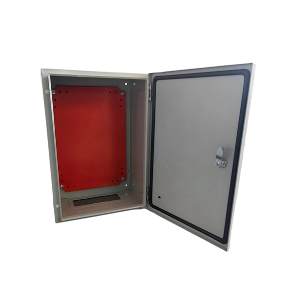
Find out the latest 2025 electrical rewiring costs in Singapore, including DB box upgrades and socket installation. Get fast, free quotes from licensed electricians — no hidden fees, guaranteed safety. Our power distribution boxes are designed to provide reliable and efficient power distribution for various applications. Made from high-quality materials, our boxes are durable and can withstand harsh outdoor conditions. They are available in different sizes and shapes to fit your specific needs. ₱ 90 | 5. 5-6 ONLY! Shop power distribution box for sale online on Shopee Philippines! Read user reviews and discover exciting promos. Enjoy great prices on power distribution box and other products!. According to recent market analysis, the global distribution boards market is projected to grow from USD 7. 6 billion in 2024 to USD 12. For merchants considering how to sell on Alibaba. com. Our DB box installation services are ideal for various situations, including old homes with aging circuit breakers that require replacement, and new properties where the existing electrical circuits may be inadequate for the needs of modern living. Our 24 hour electrician Singapore team of.. Power socket installation (per point): ~ $60–$130+ (surface). Concealed is higher due to hacking/reinstatement. DB box / distribution.
[PDF]