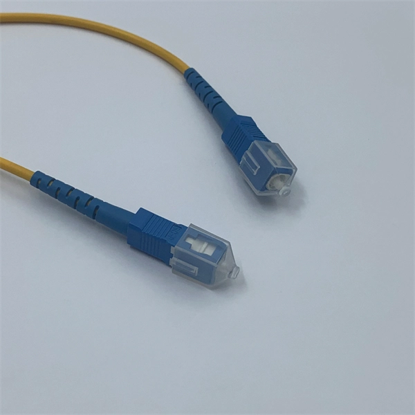
During installation under tension, maintain a minimum bend radius of 20 times the cable's outer diameter, while post-installation requires a minimum long-term bend radius of 10 times the cable diameter. Following these cable specifications prevents optical signal loss, attenuation, and physical. Fiber optic cable bend radius is a critical mechanical parameter that determines how sharply a cable can be bent without risking microbending, macrobending, signal loss, or long-term structural fatigue. Proper bend radius control ensures the integrity of optical performance and protects the glass. All fiber optic cables have specifications that must not be exceeded during installation to prevent irreparable damage to the cable. This includes pulling tension, minimum bend radius or diameter and crush loads. Installers must understand these specifications and know how to install cables without. This article provides a practical, installation-focused guide to fiber bend radius, including definitions, standards, common mistakes, and best practices. What Is Fiber Optic Bend Radius? The fiber optic bend radius refers to the smallest radius a fiber cable can be bent without causing. The correct bend radius calculation is a fundamental prerequisite for high-quality fiber optic installations and is decisive for long-term network performance and reliability. Use bend-insensitive fiber optic cables in tight spaces to reduce signal loss and allow sharper bends, but still follow.
[PDF]
Our CAD drawing files are available as . STP files for download. Discover Autodesk Revit's RVT format for our T&B cable tray BIM files. With its intuitive interface and robust features, Revit streamlines design, offering enhanced customization. Access and download T&B cable trays Revit files for free now! Find and download Intergraph Smart 3D CAD VUE files for. Our CAD drawing files are available as. Discover all CAD files of the "Cable trays" category from Supplier-Certified Catalogs ✅ SOLIDWORKS, Inventor, Creo, CATIA, Solid Edge, autoCAD, Revit and many more CAD software but also as STEP, STL, IGES, STL, DWG, DXF and more neutral CAD formats. can access every toolset, what can you do that you couldn't do before? Do you know that you can use AutoCAD MEP software to create cable tray, hanger, conduits pipe fitting, and MvParts that you can use in AutoCAD Plant 3D software? Getting started with the parametric parts can intimidate a new. Tray installation details for the location of a project's electrical wiring; in addition to blocks with different angles that allow the wiring circulation to be identified. Free CAD and BIM blocks library - content for AutoCAD, AutoCAD LT, Revit, Inventor, Fusion 360 and other 2D and 3D CAD applications by Autodesk. You can exchange useful blocks and symbols with other CAD and BIM users.
[PDF]