Simple 3-phase distribution board wiring diagram for home use, showing safe connection of power supply, breakers, neutral, and earth for residential electrical systems. Hey, in this article we are going to see the Three (3) Phase Distribution Board Wiring Diagram and Connection Procedure. The three-phase distribution board is used to distribute power to the three-phase loads and circuits such as three-phase motors, three-phase machinery, three-phase to. In a newly constructed residential area, a 10kV power line is introduced into the substation. After stepping down the voltage through the transformer's low-voltage side (0. The following is a detailed introduction about it: - **First-level Distribution. Utilities may have some control over and access to the energy stored in electric vehicles attached to the grid. ndards and conformity assessment activities in the United States. ANSI facilitates and promotes voluntary consensus standar rty or economic loss due to fire, electrical and related hazards. They deliver information and knowledge through more than 300 consensus codes and nspection to protect people.
[PDF]
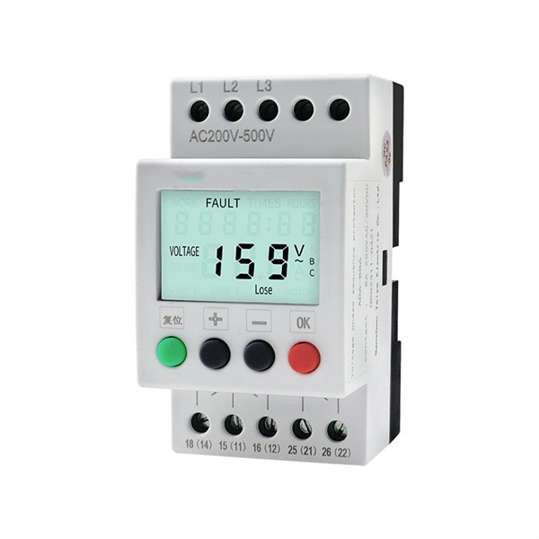
Smart circuit breaker boxes offer advanced features like energy monitoring, remote control, and enhanced safety compared to traditional breaker panels. Smart circuit breaker boxes are electrical control devices that integrate smart technology and provide remote monitoring and. Today's smart electronic circuit breakers and electronic trip units, like those represented in ABB's SACE® Tmax XT and Emax 2 breakers, represent a distinct shift in how you might deploy and manage smarter power distribution solutions. In this guide, we will explore the definitions, types, functions, and applications of intelligent circuit breakers. Intelligent circuit breakers. Regular circuit breakers offer essential protections like overload protection, short circuit protection, and leakage current protection: Overload Protection: This feature safeguards the circuit from excessive currents that can occur when too many devices are connected or a device is faulty. Upgrade your home's electrical system today. The GRD9S-F100 is a smart Smart MCB equipped with RS485 communication, designed for intelligent power distribution and energy. Smart circuit breakers are becoming essential for modern homes in 2025 – With rising energy costs and increasing smart home adoption, these devices offer 5-30% energy savings through real-time monitoring and automated load management, making them a valuable investment for homeowners looking to.
[PDF]
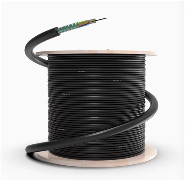
Roadside Telecommunications (RS-TC) Fiber Optic Cable Installation Adjusted Capital Cost Scatter Plot The data used to produce this cost plot are sourced from the ITS Sample Unit Costs Database. These cost data are obtained directly from a variety of sources. Buying fiber optic installation services involves several cost components, with total price influenced by length, location, and access. The main cost drivers include trenching or aerial deployment, materials, labor hours, and any required permits. This guide presents typical price ranges in USD to. Costs to run fiber optic cable vary by distance, trenching needs, cable type and labor rates. This guide outlines typical price ranges and what drives the total cost for U S buyers. Commercial building installations with 100-200 network drops generally range from $15,000 to $30,000. You should account for permit. Typically, per drop fiber cabling prices range from $250 – $1000 per drop depending on the type of fiber (OM2, OM3, OM4, or OM5), multi or single mode, PVC or plenum, average drop length, and also the number of fibers in each cable. Unit cost descriptions have not been.
[PDF]
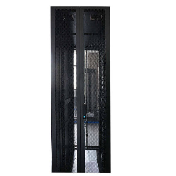
Rack Elevation or Server Rack Layout Software are simple tools to plan and document the cabling of your server cabinet. To make it even easier for you, we launched the free online Rack Planner. It helps you create a helpful rack diagram and keep your network tidy. Network cabinet cabling describes the structured connection and arrangement of all IT components in a server rack. The aim is a secure, maintainable and scalable operation of the network environment. Step-by-step guide: In this way, patch panels, switches, cable routing and documentation are. Creating a rack diagram is an important step to having sustainable good cable management in the network cabinet. Let's take a look at the essential components, selection criteria, and best practices for efficiency, order and protection of the network. Use cabinet screws to fix the network patch panel to the network cabinet. Note the wiring sequence on the patch panel when wiring, as T568A and T568B have different sequences. Wiring a server or network rack feels simple at first. Cables plug in, and devices turn on. Then problems appear. Slow speeds and tangled wires with card troubleshooting. Clean wiring prevents those issues before they start.
[PDF]
Ever wondered how pigtail bolts—critical components in power line fittings—are made? Watch as we take you through the entire manufacturing process step by st. How to Make Electrical Pigtails: This is a basic tutorial on what electrical pigtails are and how to make them. Disclaimer: Always use multiple sources and do your homework before performing any electrical work. Also, make sure all work is done within national and local code. Let's look at how to make pigtail wire links below. Also, it can join several wires to become a single conductor for electrical connections. Let us suppose I had 14 shielded wires to bring into a 15-pin connector where only one pin was available for shield grounds. Imagine how fat a lump there will be if all the shield terminations are located right next to. Bulb to Socket & Component to Connector Cross Reference Guide des spirales de raccord et des douilles Renvois ampoules/douilles et composants/connecteurs Guía de cables flexibles y adaptadores Referencias a bombillas/adaptadores y componentes/conectores NAPA®ECHLIN IGNITION, EMISSION, ENGINE. Pigtail connections are most frequently used to ground a switch or electrical outlet and for electrical devices that need to connect to multiple circuit wires. They also come in handy to lengthen circuit wires that are too short to reach a device. A pigtail is composed of three strands of wire.
[PDF]
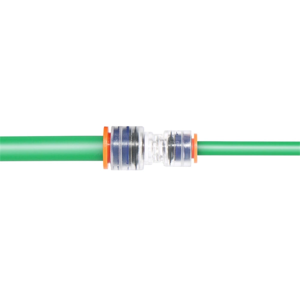
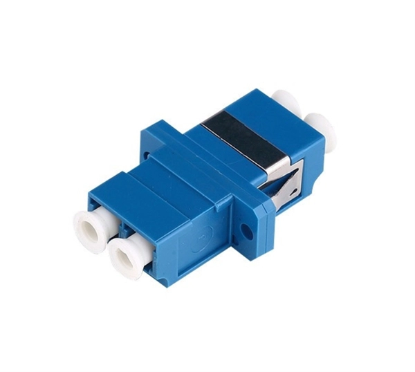
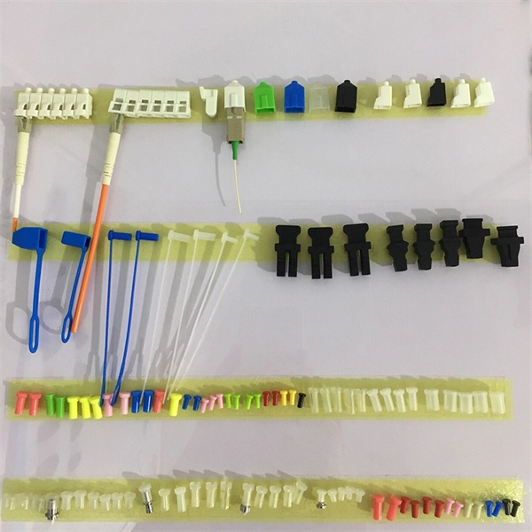
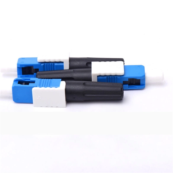
A fiber optic pigtail is a short length of optical fiber —typically 0. 5m to 2m—that has a factory-terminated connector on one end and bare fiber on the other end. The connector end is polished and tested under factory conditions, ensuring low insertion loss and high return loss. They are the bridge between fiber optic cables in the field and the equipment or patch panels that manage them. By combining factory-installed connectors with spliced bare fiber, pigtails ensure that network installers can create fast, reliable, and cost-effective terminations. Without pigtails. What is a Fiber Optic Pigtail, and What Is It Used For? Written by Ben Hamlitsch, trueCABLE Technical and Product Innovation Manager RCDD, FOI A fiber optic pigtail is a type of fiber optic cable with only one end that has a factory-terminated connector and the other end exposed as bare fiber. ) fitted on one end and the other end undressed (for connection through fusion or splicing) to the main fiber optic cable. It is usually suitable for field termination using a mechanical or fusion splicer. Compared with quick termination or epoxy and polish connections placed on the field. Fiber optic pigtail offers an optimal way to joint optical fiber, which is used in 99% of single-mode applications. This post contains some basic knowledge of fiber optic pigtail, including pigtail connector types, fiber pigtail classifications.
[PDF]
Download a comprehensive set of Cable Tray Installation CAD Blocks in DWG format, ideal for electrical engineers, MEP designers, and industrial layout planners. This article shares simple ways to plan your cable trays and wiring. We want to help electrical engineers, technicians, and anyone working with electrical setups build safe and good systems. This collection includes installation details for ladder trays, perforated trays, solid-bottom trays, and wire mesh trays, along with. This guide provides step-by-step instructions on installing a cable tray on a wall, covering different types of cable trays, tools needed, and safety tips. The Ladder Tray features light, rugged, tubular steel construction. It is designed for. In industrial settings, electrical and instrumentation (E&I) cable trays or bridge racks play a critical role in organizing and supporting power, control, and signal cables across facilities. An effective layout ensures safety, minimizes interference, reduces maintenance time, and keeps the overall. ALL TO BE CLEANED WITH A COMMERCIALLY AVAILABLE CLEANSER PRIOR TO ALL MARKERS AFFIXED PRIOR TO INSTALLATION OF ANY CABLE. BONDING JUMPER SHALL BE INSTALLED FOR ELECTRICAL CONTINUITY ACROSS ALL DETAIL AT INTERFACES AND/OR CONDUIT BUSHINGS SHALL INSTALLED FCR ENTRY OF CABLES.
[PDF]
We here listed 10 Corrugated Carton Boxes Manufacturers & Suppliers in Dominican Republic. Suneco Box is a professional Corrugated Boxes Packaging Solution Supplier. Ask. We have a highly trained team, a large inventory of raw materials, production up to 50,000 daily cases, competitive prices and the experience to meet with success at national and international markets. Our company focuses on innovative, cost-effective, and high-quality packaging solutions, that. Standard folding cartons can be customized and enhanced with special materials and our range of processes that ensure a premium finish. International Packaging Company, Inc. main business focus is the manufacturing of specialty packages with its production facility located in Parque Zona Franca. If you are looking for Paper Packaging Boxes Manufacturers and Suppliers in Dominican Republic, you are on the right place. We are a group of companies engaged to the manufacture and marketing of packaging products for the Food, Beverages, Industrial and Pharmaceutical industry. We currently have three product lines. was established in 2007 with the goal of being a leader group for packaging solutions.
[PDF]
This video makes connecting your fiber optic cable to your router a breeze! We'll guide you through the entire process step-by-step, ensuring a smooth and hassle-free experience. Our Experts are helping user's, who are facing issues with their tech gadgets like. In this guide, we'll walk you through how to connect a fiber optic cable to a router safely and efficiently. Why Use Fiber Optic Internet? Before diving into the setup, let's quickly recap why fiber optics are worth the effort: Lightning-fast speeds (up to 1 Gbps or higher). This comprehensive guide combines industry standards with field-tested practices to ensure you achieve a rock-solid. Setting up a fiber internet connection requires understanding key hardware components and following a specific connection sequence to establish your home network. This guide details the necessary physical and digital steps to connect your fiber line and activate your internet service. If you. Connecting a fiber optic cable to a router might seem daunting at first, but with the right tools and a bit of patience, it's a straightforward process. Here's a step-by-step guide to help you through it. Check compatibility: Before you begin, make sure your router supports fiber optic connection. Not all routers can connect directly to a fiber cable, so it is important to verify this information before continuing.
[PDF]
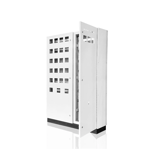
Welcome to our channel @Electricalgenius In this video, we'll take you through a detailed step-by-step guide on wiring a home distribution DB (Distribution Board) box. Learn how to install a distribution box safely and correctly. Covers wiring, placement, standards, and expert tips for a compliant setup. It takes the incoming power and safely distributes it to different circuits throughout your building. This article details the process of installing them, which helps you comprehend distribution boxes. This page contains wiring diagrams for a service panel breaker box and circuit breakers including: 15amp, 20amp, 30amp, and 50amp as well as a GFCI breaker and an isolated ground circuit. This diagram illustrates some of the most common circuits found in a typical 200 amp circuit breaker service. An electrical panel box, also known as a breaker box or a distribution board, is a crucial component of any electrical system. It serves as a central hub for distributing electricity throughout a building, ensuring that power is delivered safely and efficiently to all the required locations. You can find electric panels inside cabinets, behind refrigerators, or inside clothes closets in older homes. Current National Electrical Codes (NEC) allow none of these locations. Electrical panels.
[PDF]
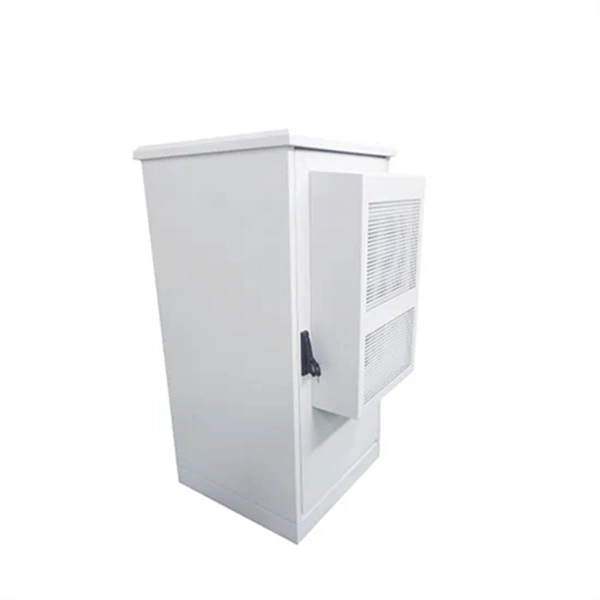
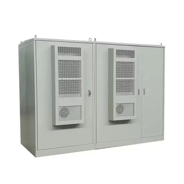
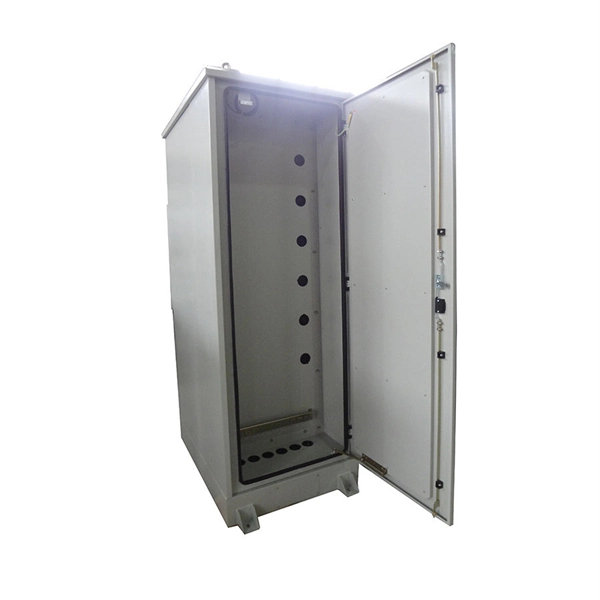
Nordic Fiberglass manufactures box pads for pad mount transformers, switchgear, and other pad mount equipment, sectionalizing cabinets, secondary pedestals, ground sleeves, hand holes and hill holders. Nordic Anti-Corrosion Supplies is a newly established company based in Sønderborg, Denmark, dedicated to providing high-quality equipment to the surface treatment industry. Get in touch with us! Copyright © 2026 Nordic Lights Ltd. All Rights Reserved. Search for a product. Born in Sweden 10 years ago, zebra® accompanies professionals in search of high-quality lighting solutions. The brand's reputation has been built around its strengths: design, technical expertise, reliability. Its. Zhejiang Guozhong Explosion-proof Electrical Co. is an all-inclusive manufacturer of explosion-proof electrical (electronic) equipment, covering design, research and development, production, inspection, sales and after-sales services. The company mainly produces over 150 series and 1,200.
[PDF]
Installing a fiber optic splitter involves several crucial steps to ensure proper functionality and reliability. Here's a step-by-step guide to help you through the process:. In this guide, we'll walk you through how to connect a fiber optic cable to a router safely and efficiently. Why Use Fiber Optic Internet? Before diving into the setup, let's quickly recap why fiber optics are worth the effort: Lightning-fast speeds (up to 1 Gbps or higher). Low latency for. The process to connect fiber optic cable to router requires careful attention to detail, but I'll walk you through every critical step with the precision and clarity you deserve. Our Experts are helping user's, who are facing issues with their tech gadgets like Router, Modem and extender. If you. Setting up a fiber internet connection requires understanding key hardware components and following a specific connection sequence to establish your home network. This guide details the necessary physical and digital steps to connect your fiber line and activate your internet service. Check compatibility: Before you begin, make sure your router supports fiber optic connection. Not all routers can connect directly to a fiber cable, so it is important to verify this information before continuing.
[PDF]
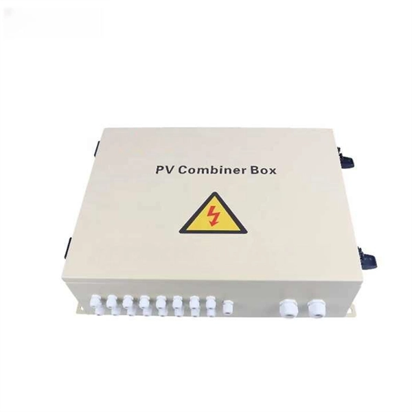
In this video, we'll walk you through the process of wiring a home distribution box with a detailed connection diagram. Whether you are an electrical contractor or a construction brigade, knowing how to properly and safely install distribution boxes is the basis of ensuring the safe operation of the entire system. This article details the process of installing them, which helps you comprehend distribution boxes. In modern electrical systems, cable distribution boxes (also known as electrical distribution boxes or distribution boxes) play a crucial role as the key hub for managing, distributing, and protecting circuits. Covers wiring, placement, standards, and expert tips for a compliant setup. A distribution box is the heart of any electrical system. It takes the incoming power and safely distributes it to different circuits throughout your building. What is Distribution Board? Distribution board. Mounting new electrical boxes is a simple process, but the job does require careful planning. You don't have to create a to-scale.
[PDF]
In this step-by-step tutorial, we'll cover: ✅ Tools you need ✅ Safety precautions ✅ Mounting the box ✅ Wiring tips ✅ Final checks Perfect for beginners, DIYers, and electricians who want a clear installation guide. more Learn how to properly install an electrical box safely. A distribution box is the heart of any electrical system. It takes the incoming power and safely distributes it to different circuits throughout your building. Whether in a home or an industrial facility, this box keeps your electrical setup organized, functional, and efficient. It serves as a central hub for distributing electricity throughout a building, ensuring that power is delivered safely and efficiently to all the required locations. Plastic electrical boxes are a great option for DIY home remodelers as they are lightweight, affordable, and easy to work with. They are often used when adding outlets or switches to finished walls or ceilings.
[PDF]
Pick the right size distribution box to keep things safe. This stops too much power and keeps wires from getting too hot. It also lets you add more stuff later if needed. Use electrical diagrams to see where circuits go. Diagrams are like maps for your wires. They help you. A neat, well-organized service panel or subpanel is easier and safer to work in; it will also be an easier panel in which to add circuits later on. A neat, well-organized subpanel bundles wires to conserve space and improve access. Ideally, wire groups are installed in layers and wires are bent at. In this video, we'll walk you through the process of wiring a home distribution box with a detailed connection diagram. It serves as a central hub for distributing electricity throughout a building, ensuring that power is delivered safely and efficiently to all the required locations. A distribution box is the heart of any electrical system. Whether in a home or an industrial facility, this box keeps your electrical setup organized, functional, and efficient. Material preparation: Prepare the required circuit breakers, wires, wiring ties and other materials, and ensure that they meet the design drawings and installation requirements. Location determination:. A single phase breaker box, also known as a distribution board, is an electrical panel that controls and distributes electrical power in residential and commercial buildings. The wiring diagram.
[PDF]