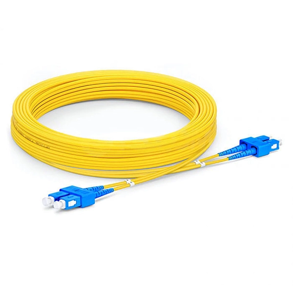
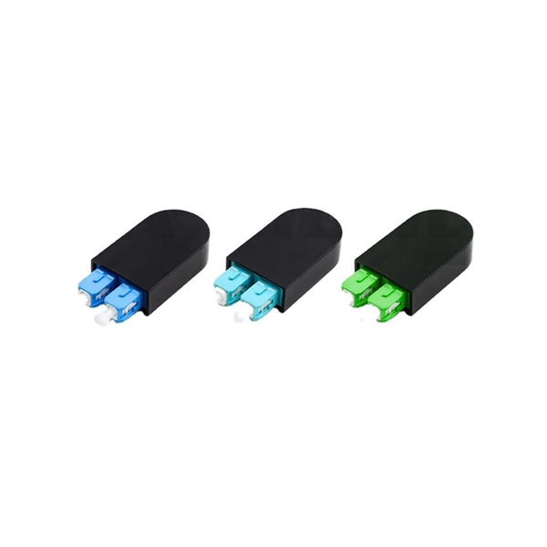
The other side of the pigtail is open and is connected to a fiber optic cable. This creates a stable and reliable connection between network equipment. They are the bridge between fiber optic cables in the field and the equipment or patch panels that manage them. By combining factory-installed connectors with spliced bare fiber, pigtails ensure that network installers can create fast, reliable, and cost-effective terminations. DINTEK supplies this equipment, but the pigtails can also be. In the intricate ecosystem of fiber optic networks, two components play a critical role in ensuring seamless connectivity: patch cords and pigtails. A fiber optic pigtail is a type of fiber optic cable with only one end that has a factory-terminated connector and the other end exposed as bare fiber. When compared to field-installed rapid. Today, I'll show you how to pick the right patch cord or pigtail — step by step. You plug it into a switch, router, or patch panel. It's ready to use out of the box. A pigtail is for splicing.
[PDF]
CRU provides comprehensive, accurate and up-to-date price assessments and research reports for bare optical fibre across various key regional markets, combined with insights into the factors and events affecting markets. Market Forecast By Mode (Single Mode Fiber, Multi-Mode Fiber), By End-Use (Telecommunications, Networking, IT & Data Centers, Broadcast), By Application (Telecommunication, Power Utilities, Medical, Industrial), By Fiber Type (Glass Fiber, Plastic Fiber) And Competitive Landscape How does. Based on our observations and market communication with upstream suppliers, the single-mode fiber market in China has experienced an unprecedented price surge in the first two months of 2026. This article summarizes the latest fiber optic price data as of March 9, 2026, along with the recent. According to APO Research, The global Fiber Optic Cables market was valued at US$ million in 2023 and is anticipated to reach US$ million by 2030, witnessing a CAGR of xx% during the forecast period 2024-2030. North American market for Fiber Optic Cables is estimated to increase from $ million in. How does 6W market outlook report help businesses in making decisions? 6W monitors the market across 60+ countries Globally, publishing an annual market outlook report that analyses trends, key drivers, Size, Volume, Revenue, opportunities, and market segments.
[PDF]
We terminate fiber optic cable two ways - with connectors that can mate two fibers to create a temporary joint and/or connect the fiber to a piece of network gear or with splices which create a permanent joint between the two fibers. Proper connection of fiber optic cables is essential to harness these benefits fully, as even minor errors can lead to significant performance issues like signal loss. These terminations must be of the right style, installed in a. Running fiber internally involves extending this high-speed link from the service entry point to a centralized location, such as a dedicated media closet or network rack. This DIY effort is undertaken to maximize performance, improve aesthetics, or relocate the Optical Network Terminal (ONT) to a. In this video, we'll guide you through preparing and terminating fiber optic cables using SimplyFiber products, known for their high quality, ease of use, and reliability. more Audio tracks for some languages were automatically generated. Two types of splices are used in fiber optic cabling one is Mechanical the other is Fusion. Whether you're installing a new network, expanding an existing one, or. But here's the thing: how you connect fiber optic cable really matters. A shaky connection means weaker signals, dropped streaming, or slow uploads. Get the hookup right, and you'll enjoy streaming, gaming, and video calls without interruptions.
[PDF]
Abstract: Detecting partial discharges in cable joints is critical for timely defect identification and reliable transmission system operation. The electric field distribution of the optical fiber-implanted cable joint was simulated, followed by electrical performance tests, demonstrating that optical fiber implantation had a negligible effect on the electrical properties of the cable joint. A platform utilizing Mach–Zehnder–Sagnac. The results show that the average sensitivity of the sensor in the 10 kHz–80 kHz range is 71. 0 dB higher than that of the piezoelectric transducer, with a maximum signal-to-noise ratio of 65. To improve the long-term reliability and sensitivity of the sensing system, a novel method for cable joint monitoring based on implanting optical fibers. However, there is an industry gap in the literature about the highly sensitive fiber optic-based PD solution based on the acoustic emission principle. This paper aims to fill such an industry gap. In this paper, the fiber optic-based PD sensing (OptiFender) technology is applied to monitor the PD.
[PDF]

Discover the key differences between optical fiber cables and copper cables. OPTRAL analyzes the advantages and disadvantages to enhance connectivity. Optical and copper interconnection technologies represent two distinct approaches to data transmission, each with its own advantages and limitations. While fiber optics dominate in performance, copper retains its technical and economic justification. But how do you decide which one is best suited for your needs? This article delves into the technical comparison between copper and fiber optic cables. When it comes to modern data transmission, Fiber Optic cables and Copper Cables play pivotal roles in ensuring seamless connectivity. What Are Fiber Optic Cables? Fiber Optic cables function by transmitting data in the form of light pulses through optically pure glass fibers. These fibers are. “Fiber offers multiple technical advantages, including exceptional bandwidth, low attenuation and distortion over long distances, reduced bulk, as well as isolation from electromagnetic interference (EMI) and electrostatic discharge (ESD). ” Let's explore the characteristics, advantages, and. The two core material technologies used in almost all cables are fiber optic, and copper wiring. Whether you're looking at an HDMI cable, a USB cable, Ethernet patch cable, or any other kind of network of data transmission cabling, they are all built using copper or fiber optic internal wiring.
[PDF]
The vertical clearance for overhead fiber optic lines above the highway must be a minimum of 18 feet. The exception is ADSS cables which are approved for installation in the power space by qualified personnel. All aerial cables should be installed clear of any obstructions. The Fiber Optic Association, Inc. (FOA) was founded in 1995 to help develop the workforce to build the fiber optic networks to support a rapid expansion in communications and the Internet. The charter of the FOA was to promote professionalism in fiber optics through education, certification, and. The basic pole height is 7m and the tip diameter is 150mm. In case of special sections, crossing obstacles or roads or railways, the pole height of 8m, 9m, etc. can be selected according to the actual terrain. If the surface is stone, the depth needs to be 0. 9m, and if the surface is other soil. Generally a 12 inch to 24 inch soil separation is recommended as a safety barrier and for locating purposes. 9938 | SuperiorEssexCommunications. com Page 1 of 4 TECHNICAL GUIDELINE July 30, 2020 TG030 Rev. FIBER is used for relocating any fiber optic cable from one location to another. Field conditions will vary, so the actual location. to n utral comm.
[PDF]
In 2024, Top exporters of Optical fibre cables, made up of individually s are China ($2,363,805. 65K, 379,127,000 Kg), United States ($1,645,814. 71K ), Mexico ($1,313,955. 67K, 18,156,300 Kg). 17 billion (according to external trade statistics of 117 countries). There are no trade data (2023) for such exporters as Korea. Asian countries collectively account for nearly 50% of global exports, with China dominating in both sectors. Looking at both optical fiber and optical cable, China ranks first with an export share of 29. 6%, followed by the United States (12%) and Mexico (11%), which shows that technology is highly. Volza's Big Data technology analyzes over 3. 5 billion verified shipment records across 203 countries to help exporters and importers identify new Fiber Optical Cable buyers and suppliers, discover profitable markets, and connect with reliable trade partners worldwide. According to Volza's Global. Analyze Fiber Optical Cable export import data and locate key markets, reliable suppliers, and active buyers by utilizing Eximpedia's data-centric platform. Whether you're a supplier looking for high-demand markets or a buyer sourcing Fiber Optical Cable from reliable exporters, Eximpedia's. Find verified buyers and sellers of fiber optic cables in 180+ countries along with their valid phone numbers and email ids. The top 3 Buyer countries for fiber optic cables are “ CHINA ”, “ UKRAINE ”, “ UNITED STATES OF AMERICA ”,.
[PDF]
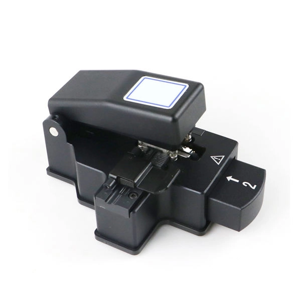
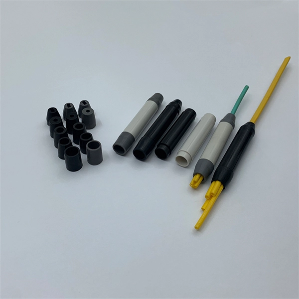
Get the wrong connector type, the wrong polish, or skip proper fusion splicing technique—and you're looking at elevated signal loss, increased back reflection, and a field termination that fails certification. Once you nail the logic chain— raw fiber → protected cable → spliced pigtail interfaces → flexible patching —you control loss budgets, installation time, and maintenance risk. Key takeaway: Treat the four items like a relay team. Each runs a specific leg so your network hits performance targets. In the intricate ecosystem of fiber optic networks, two components play a critical role in ensuring seamless connectivity: patch cords and pigtails. While both are essential for linking fibers to devices or other cables, they serve distinct purposes and are designed for specific scenarios. Executive Summary: A fiber optic pigtail is one of the most commonly specified yet least understood components in structured cabling. Despite their widespread use and numerous advantages, there are some circumstances in which they might not be the ideal option. A fiber optic pigtail is very practical for on-site terminations where fusion or mechanical splicers are used. Preterminated connectors offer several advantages over. Today, I'll show you how to pick the right patch cord or pigtail — step by step. A Fiber Patch cord connects two devices. You plug it into a switch, router, or patch panel. It's ready to use out of the box. A pigtail is for splicing.
[PDF]
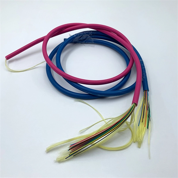
Fiber optic "cable" refers to the complete assembly of fibers, other internal parts like buffer tubes, ripcords, stiffeners, strength members all included inside an outer protective covering called the jacket. Cable provides protection for the optical fiber or fibers within it appropriate for the environment in which it is installed. You will also learn how different aspects of the product can affect budget and design. ■ The Five Key Parts of a Fiber Optic Cable A fiber optic cable. A fiber optic cable consists of five basic components: the core, the cladding, the coating, the strengthening fibers, and the cable jacket. When searching for a fiber optic cable, we need to pay attention not only to the connectors, such as SC to ST fiber cable, LC to SC fiber patch cable, or SC to. A TOSLINK optical fiber cable with a clear jacket. These cables are used mainly for digital audio connections between devices. This advanced cabling solution allows fast, secure data transfer and telecom over long distances. Understanding the components within a fiber optic cable enables. While fiber optic cable itself is cheaper than an equivalent length of copper cable, fiber optic cable connectors and the equipment needed to install them have typically been more expensive than their copper counterparts.
[PDF]
This Technical Brochure describes the induction phenomena (inductive, capacitive and conductive) that can lead to presence of voltage and currents on disconnected cable systems. The optical fiber composite overhead ground wire (OPGW) has been widely used in power transmission lines. Methods of calculation to evaluate those values and touch voltages are detailed and analysed, associated with various. working on cables u al, photocopying, recording or otherwise, without the prior written or use by members of the Energy Networks Association to take account of the conditions which apply to them. Advice should. Literature review: An in-depth literature review covering the modelling and calculations of the conditions relating to faults caused by interactions between fibre optic cables and power cores in submarine cables. Examples of electrically conductive installations where induced voltage may occur could be: • Overhead lines or cables out of opera- tion •.
[PDF]
NEC (National Electrical Code) Article 800 covers the general requirements for communications systems, including wiring methods, grounding, fire resistance, and installation practices for cables and equipment. The term “cable” means stranded conductor or a combination of conductors that includes Fiber Optic Supply Cable, Fiber Optic Communication Cable, or Non–Dielectric Fiber Optic Cable as defined in Rule 20. The term “messenger” is defined in Rule 22. The. This Applications Engineering Note (AE Note) discusses conventional bonding and grounding practices for conductive fiber optic cable and hardware installations within the scope of the National Electrical Code (NEC). This AE Note does not address outside plant fiber optic installations or. ned herein and with other Sections of this Specification as applicable to the completion of the installation. It applies to circuits that extend from the communications utility (such as telephone or. Article 800”General Requirements for Communications Systems covers general requirements for installing communications circuits, community antenna television and radio distribution systems, network-powered broadband communications systems, and premises-powered broadband communications systems. to n utral comm.
[PDF]
Since fiber-optic cables use light to transfer data instead of electricity they actually generate less heat than traditional cables! This absence of heat makes them less likely to catch fire and less of a fire hazard than normal metal wires. A rigorous analysis of optical power density, thermal ignition mechanisms, and the role of Automatic Laser Shutdown in preventing fire hazards in EDFA-amplified fiber networks. Article Inspiration This article was inspired by the Fiber Optic Association (FOA) March 2026 Newsletter — Seen On The. Myth #1 – Fiber-optic cables are a fire hazard. The general assumption is simple: once installed, the cable does its job – transmitting data from point A to B – and that's it. Understanding the safety hazards that go with fiber optic cable is critical for those who install or maintain fiber optic systems. As electrical professionals, most of us take fiber optic (FO) safety for granted. Since fiber optic cable carries no electricity, we don't worry about electrocution. This means they won't produce sparks or arcs that could ignite a flammable atmosphere. In a Class I Division 1 or Zone 1. Fiber-optic cables are the backbone of modern connectivity—powering 5G networks, global internet backbones, and data center interconnections with near-light-speed data transmission. While these cables are engineered for durability (with some rated to last 25+ years), they are not invulnerable.
[PDF]
Use this worksheet to input values for all variables that will impact your system's performance. After entering your values, please ensure you click the 'Calculate Link Loss' button at the bottom of the page to generate your total link loss. Add connectors, splices, bends, and safety margin easily. See results instantly above the form, then adjust values. Choose a mode, then enter values and optional losses. All calculations use base-10 logarithms. mW must be greater than zero. Used only in measured attenuation mode. Length is needed. The power budget refers to the amount of fiber optic cable plant loss that a datalink (transmitter to receiver) can tolerate in order to operate properly. Sometimes the power budget has both a minimum and maximum value, which means it needs at least a minimum value of loss so that it does not. To detect whether the link runs properly, the following calculation should be performed. It is often the case to calculate the maximum signal loss across a given fiber link during optical cable installation. First, you should be aware of the fiber loss formula: The Total Link Loss = Cable. Therefore, it is very important to calculate the fiber loss and take appropriate steps. In order to get the most reliable results, an Optical Time Domain Reflectometer (OTDR) trace of the actual fiber connection should be completed. This will provide you with the real.
[PDF]
BARCELONA, Spain, March 6, 2025 /PRNewswire/ -- At the Mobile World Congress 2025 (MWC 2025), Huawei launched the StarryLink optical modules, designed to enhance network experiences with "3S" quality (Spanning, Stable, Secure). This announcement occurred during the data center session titled. Very little is written about Huawei's optical DWDM technology, but that doesn't mean the company hasn't made some big waves in the industry. We had the chance to sit down with the Huawei optical team, led by Gavin Gu, at MWC 2026 to learn about their latest coherent DWDM technology.
[PDF]
This guide provides a fully updated and industry-ready overview of LC fiber optics, explaining the origin and design of LC connectors, their key features, and the complete ecosystem of LC-based products used in modern networking. LC fiber connectors, as the most well-known representative of SFF (Small Form Factor) connector, are widely adopted in today's LAN and data center cabling. You may find LC connector has a strong family which includes but not limited to LC optical fiber connectors, LC fiber patch cables, LC fiber. Data centers will keep dominating optical module demand as AI and cloud drive revenue growth through 2030. Optical module demand is being pulled in two directions at once, faster bandwidth for dense networks and tighter constraints on power, security, and lead times. With global R&D projected to. LightCounting has proudly served our industry for 22 years with reports and services designed to help executives plan and run their businesses. We support decision-making based on our data, expert analysis and trusted forecasts. It covers LC connectors, LC patch cables, uniboot designs, armored. Optical Module Package Market was valued at 8942 million in 2024 and is projected to reach US$ 20220 million by 2032, at a CAGR of 12. With the surge in data traffic and the increasing demand for higher bandwidth, 100G optical modules have gained immense traction. These modules facilitate high-speed.
[PDF]