Calculate power supply wattage by multiplying the total power consumption of all PC parts by 1. This article explains how to check CPU and GPU power usage, estimates for other components, the reason for multiplying by 1. 5, and introduces a calculation tool. Calculating the power supply unit's wattage may seem troublesome, but there is also a tool that calculates the power supply wattage just by selecting parts, so please use it. Modern systems draw power primarily from the CPU and GPU, with motherboards, memory, storage, and peripherals contributing smaller amounts to total system load. High-performance processors in 2026. Our advanced power calculator tool precisely calculates the wattage needed based on your selected components, ensuring optimal performance and compatibility. Select your components, get accurate power estimates, and find the right PSU with proper headroom and efficiency rating. It can be used to select a proper power supply unit for your system. It can also be used to calculate the cost of. Calculate your PC's exact power consumption and get instant PSU recommendations with safety headroom. Build with confidence using accurate TDP data for CPUs, GPUs, and all components. Stop guessing PSU wattage and avoid expensive mistakes.
[PDF]
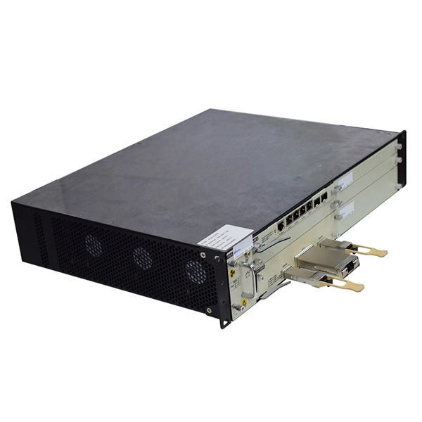
An optical transport network (OTN) is a digital wrapper that encapsulates frames of data, to allow multiple data sources to be sent on the same channel. This creates an optical for each client signal. defines an optical transport network as a set of optical network elements (ONE) connected by links, able to provide functionality of transport, multiplexing.
[PDF]
800G optical modules provide 2× bandwidth and ~30–40% better power efficiency per bit than 400G, while reducing fiber count significantly. However, 400G remains more cost-effective for enterprise workloads, and 1. 6T is still in early deployment stages primarily targeting AI-scale data. 400G, 800G, and 1. 6T is growing exponentially. This surge is driving technological upgrades in optical modules toward higher data rates. NADDOD, the leading optical modules. Developments in three distinct areas are needed for 800G deployment: optical modules and direct attach copper (DAC) cables, switch ASICs, and 800GE standardization. Not all these need to be fully delivered for data center operators to benefit from 800G upgrades. By understanding the key. Choosing between 400G and 800G optical modules depends on your workloads, scale, and budget. This guide breaks down the differences, use cases, and deployment advice in simple but detailed terms. What are Optical Modules? An optical module (or optical transceiver) is a pluggable device inserted. Today's data center Ethernet switches are essentially optical communication devices, as the entire system operates on optical transmission principles. This article will explore the evolution of modules' speed and form factor from 400G to 1.
[PDF]
Check 400G ZR price from the latest Cisco price list 2022. Cisco Nexus 9800 36-port 400G QSFP-DD Line Card with MACsec. 4x QSFP-DD 400G ZR Bundle. QSFP-DD transceivermodule,coherentDCO,400G-ZR REMANUFACTURED. The QSFP-DD OLS is a pluggable open line system solution that can be directly hosted on a Cisco router. The Cisco ® QSFP-DD Open Line System (QSFP-DD OLS) is a pluggable optical amplifier module that, together with the channel breakout options (described later), provides a simple yet powerful open. The core difference between SFP and QSFP is lane count: SFP is a single-lane form factor (1G–25G), while QSFP aggregates 4 (or more) lanes to reach 40G, 100G, 200G and 400G (QSFP-DD). Choose by port density, target bandwidth, distance, and thermal budget. For access and 5G front-haul pick. Quad Small Form-factor Pluggable Double Density (QSFP-DD) solution that fits into high-density switch and router client ports for optical interconnect links Powered by Greylock and Delphi DSP ASICs, and silicon photonic integrated circuits (PICs) for an optimized co-packaged design with 3D. Smartoptics QSFP-DD transceivers provide cost-efficient 400G and 800G optical networking. QSFP-DD (Quad Small Form-Factor Pluggable Double Density) transceivers double the number of high-speed electrical interfaces in QSFP to achieve 400G Ethernet speeds – and double them again to reach 800G. QSFP-DD fiber transceivers utilize eight lanes as opposed to the four lanes of a QSFP+ optic.
[PDF]
Inter-data-center connectivity requires high bandwidth over long distances. Pluggable coherent optics and OTN provide efficient optical-layer transport. Link design focuses on OSNR, dispersion compensation, and FEC. Data Center Interconnect (DCI) systems connect two or more data centers together over tens or up to thousands of kilometers using optical transmission. Key aspects of a DCI solution are its capacity, flexibility and security. We have a full portfolio of Ethernet and Optical Transport Network (OTN). “The Fibre Channel Industry Association (FCIA) is a mutual benefit, non-profit, international organization of manufacturers, system integrators, developers, vendors, industry professionals, and end users. In this paper, we will discuss the current architecture and the evolution towards 400ZR inter aces along with some related key tech inks with higher rate coherent WDM interfaces. This has pushed optical system vendors to introduce specific products. As a result, DCI (Data Center Interconnect) has become a core technology for ensuring seamless communication between geographically separated data centers. This article explains what it is, why it matters, and how mainstream it I technologies support modern data center architectures. At its core, DCI relies on a set of key components and advanced technologies to ensure efficient, reliable.
[PDF]
Compare verified routers businesses, get quotes, and view ratings from Zimbabwe's leading business directory. ADSL 2/2+ Modem, Wireless N Access Point and 4-Por. TP Link AC750 Dual Band Wi-Fi 4G LTE Router Brand. TP-Link TL-WN725N 150Mbps Wireless N Nano USB Adap. Overview: Smaller locations can face big-time dem. Archer C64 AC1200 Wireless. Routers CPE SWITCHES CABINETS and RACKS Wall mount cabinets Floor Standing Cabinets SERVER RACKS CABINET ACCESSORIES TRUNKING VOIP IP-PBX VOIP PHONE MEDIA CONVERTERS COPPER TOOLS FIBRE TOOLS CONTACT US PARTNER US BECOME A DEALER HOME ABOUT US Brands CISCO SYSTEMS CUDY MIKROTIK MOLEX CES TENDA. 40 Kwame Nkrumah. New Africa House, Harare 40 Kwame Nkrumah. New Africa House, Harare By using this form you agree with the storage and handling of your data by this website. Reliable performance at great prices. Huawei Highest Speed Mobile WiFi Model E5783 -230a. PLUG - & - PLAY MOBILE WI-FI ROUTER NO CONFIGURATIONS OR SETTINGS NEEDED NO BUFFINGSNO DELAYS See more Selling a hawuei mifi. Bought it and Used it for a Month. Now selling it. Why Buy Fluke Networks Fiber Optic in Zimbabwe - Harare, Bulawayo, Chitungwiza, Mutare, Gweru, Epworth, Kwekwe, Kadoma, Masvingo, Chinhoyi from AEDHS? Especially the Fluke Networks OFP2-200-SI1625 OptiFiber Pro High-Dynamic Range OTDR w/Inspec, WiFi, 3 Wavelengths | Fiber-Optic-Meters-And-Analyzers.
[PDF]

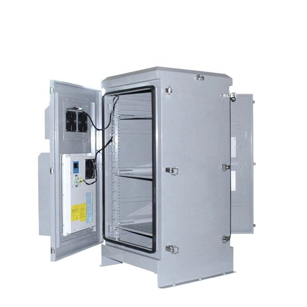
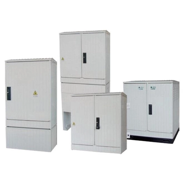
This solution covers a complete set of power equipment from low-voltage distribution cabinets, high-voltage switchgear to transformers, automation control systems, etc., aiming to provide comprehensive and customized power solutions for various users. The high and low voltage switchgear produced by Jiangsu Xinhong Electrical Equipment Co. is a type of power equipment that plays a role in power systems such as switching, control, or protection. The following is. The switchgear mainly consists of two parts: the cabinet body and the removable circuit breaker handcart. The interior of the cabinet is divided into busbar compartment, circuit breaker compartment, cable compartment and low-voltage secondary instrument compartment, equipped with a comprehensive. Our high and low voltage complete electrical equipment solutions are designed based on a deep understanding of the current development trends in the power industry and accurate predictions of future power demand. If you need parts, we can help. If you need advice and solutions, our experts are standing by, ready to listen and work with you. It is also very convenient to install and can provide stable performance output. It is safe and easy to use. The cable connectors in the tap boxes feature high-grade insulation.
[PDF]
This report provides a comprehensive analysis of the optical active device market, encompassing various segmentations: By Type: Lasers, modulators, photodetectors, amplifiers, etc., each with their own specific performance characteristics and applications. The global Active Optical Devices market was valued at US$ million in 2023 and is anticipated to reach US$ million by 2030, witnessing a CAGR of % during the forecast period 2024-2030. The Global Info Research report includes an overview of the. Optical Active Device by Application (IT Industry, Telecom, Other), by Types (Optical Transceiver Module, Light Detector, Light Modulator, Other), by North America (United States, Canada, Mexico), by South America (Brazil, Argentina, Rest of South America), by Europe (United Kingdom, Germany. The Optical Active Device Market Size was valued at 36. 3 USD Billion in 2024. The Optical Active Device Market is expected to grow from 38. North American market for Active Optical Devices is estimated to increase from $ million in 2024. Abstract—A wireline receiver consisting of a linear equalizer, a decision-feedback equalizer (DFE), a clock and data recov-ery (CDR) circuit, and a demultiplexer (DMUX) employs new circuit and architecture techniques that afford substantial power savings. Realized in 28-nm technology, the 56-Gb/s.
[PDF]
Polarization dependent loss (PDL) is a measure of the peak-to-peak difference in transmission of an optical component or system across all possible states of polarization. It is the ratio of the maximum and minimum transmission of an optical device with respect to all polarization. The determination of polarization dependent loss has become a stan-dard measurement when character-izing passive optical components. In optical networks, where polarization is not constrained and changes randomly, the PDL of components can accumulate in an uncontrolled manner. This effect can. arch, and 3) Matrix measurements using Mueller or Jones matrices. Each method has its own advantages and disadvantages in terms of measuremen ice under test (DUT) while the DUT's output power is monitored. The built-in motor con-trolled PDLE units have low insertion loss, low backreflection, low PMD and flat wavelength response. This. This is the authors' extended version of an article that has been published in Proc. 21th ITG-Symposium on Photonic Networks, ISBN 978-3-8007-5424-3. The final version of record is available at https://www. de/buecher/455423/itg-fb-294-photonische-netze. Abstract—A number. Abstract—State-of-the-art polarimeter calibration is reviewed. Producing many quasi-random polarization states and moving/bending a fiber without changing power allows finding a polarimeter calibration where the degree-of-polarization reaches unity and parasitic polarization-dependent loss is.
[PDF]
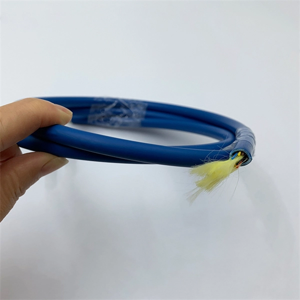
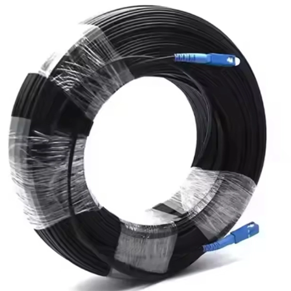
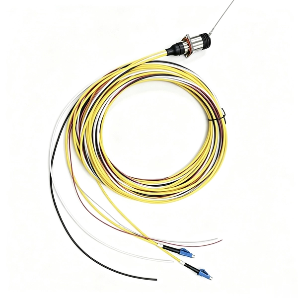
Choosing between single-mode and multi-mode optical fiber shapes the performance ceiling of every high-bandwidth industrial sensing network. This guide maps the key technical distinctions, applicable standards, and the most productive research directions for. Optical fibers are among the most transformative technologies in modern photonics, quietly enabling the global internet, precision sensing, minimally invasive medicine, and high-power industrial laser systems. The. Discover ROI-boosting fiber choices: Single Mode vs Multimode Fiber. Get the right speed & savings for your network—download our guide for free today! Understanding the physics behind Single Mode vs Multi‑Mode Fiber is essential for selecting the right conduit for any optical network. Single‑mode. Choosing single mode or multi-mode installation is unquestionably one of the most crucial decisions. Understanding the distinctions between these two kinds of fiber glass are crucial since it will have a significant impact on your network's range, bandwidth, and spending. Single mode means the. Optical fiber cable transmits data as light at speeds exceeding 100 Gbps, far surpassing the 10 Gbps capabilities of legacy Cat 6A copper cable. Additionally, optical fibers support significantly higher bandwidths over greater distances without signal degradation. While both use light to transmit data, they differ fundamentally in core structure and how light travels.
[PDF]

Thinner cables can be utilized to connect the control switch to the relay; this saves space, weight, and cost. The same voltage and current ratings as other types of switches, such as mechanical switches, do not limit relays. This handbook covers the code of practice in protection circuitry including standard lead and device numbers, mode of connections at terminal strips, colour codes in multicore cables, dos and donts in execution. Also principles of various protective relays and schemes including special protection. A control relay is an electrically operated switch that enables current to flow through a coil that closes or opens the switch. Relays use a small current to control a larger current, making them ideal for controlling high-power devices such as motors, lights, valves, and sensors. When a relay contact is open, this will switch power ON for a circuit when the coil is activated. You'll connect a low-power control circuit to the relay's coil (terminals 85 and 86), which then flips a switch for a separate, high-power circuit running through the. Electrical protection relay has two type protecton as HT panel protection and LT panel protection. HT panel protection relay. The HT power supply is received from GO switch and distributed to the. The rectangular devices are test connection blocks, used for testing and isolation of instrument transformer circuits. : 4 The first protective relays were electromagnetic.
[PDF]
Use this Protection Relay Setting Calculator to calculate pickup current, time multiplier settings (TMS), operating time, coordination time interval (CTI), and plug setting multiplier (PSM) using fault current, CT ratio, and IEC 60255 curve parameters. of protective relays in terms of protecting high voltage lines. At the beginn ng of the article it is drawn up process to protect power lines. Consequently, it is shown the method of calculation for a particular power line a d performed the calculation for setting the distance protection. These calculations are critical in industrial. ve reliable and properly coordinated relay settings. Protection coordination refers to the systematic arrangement and interaction of protective devices within an electrical distribution network to ensure that faults are isolated in a controlled and orderly manner. The. With the help of these spreadsheets below, you can make your endless calculations much easier! Contact us for more information and download:.
[PDF]
Learn how to extend GDB with optical signal breakpoints for efficient photonics chip debugging and testing with practical implementation steps. Debugging photonics chips requires specialized tools that can monitor and analyze optical signals alongside electronic ones. Legal status (The legal status is an assumption and is not a legal conclusion. Google has not performed a legal analysis and makes no representation as to the accuracy of the status listed. ) Current Assignee (The listed assignees may be inaccurate. These modules leverage advanced signal processing, modulation, and high-speed interfaces to provide high bandwidth, low latency, and reliable performance. Standard debugging tools like. modules used with NADDOD switches, for reference by technicians and users. For any questions, please contact NADDOD. When testing PRBS, there are 3 test nodes: MAC ----> PHY. In view of this, the embodiments of the present invention expect to provide an optical module commissioning device, commissioning method, and electronic equipment to solve the time-consuming technical problem of manually commissioning a DSFP optical module through a commissioning device in. Optical detection chips serve as essential components in intelligent optical computing systems, demonstrating crucial significance. These chips exhibit high sensitivity and broad wavelength response ranges, enabling precise optical signal reception and conversion while providing reliable data input.
[PDF]
The article provides an overview of protective relaying principles and their applications for high-voltage power system components. It covers the protection methods for generators, transformers, buses, and transmission lines using various relay types to detect and isolate. The rectangular devices are test connection blocks, used for testing and isolation of instrument transformer circuits. In electrical engineering, a protective relay is a relay device designed to trip a circuit breaker when a fault is detected. : 4 The first protective relays were electromagnetic. Currently resides in Orlando, FL and provides application consulting for engineers throughout the state. Proficient in all ABB/GE medium and low voltage distribution products. Also proficient in system modeling and studies with EasyPower and EMTP. Product Specialist (West Region) for Digital. IEEE/IAS/I&CPSD Protection & Coordination WG Chair Jacobs Canada, Calgary, AB rasheek. com IEEE Southern Alberta Section PES/IAS Joint Chapter Technical Seminar - November 2016 Protective Relays - Technical Seminar Nov 2016 - Copyright: IEEE 2 Abstract: Protective relays and devices. Protective relays can be classified based on their operating principle, construction, or function: 1. Based on Operating Principle Electromechanical Relays: Work using moving parts and electromagnetic forces (traditional relays). Static Relays: Use electronic components without moving parts.
[PDF]
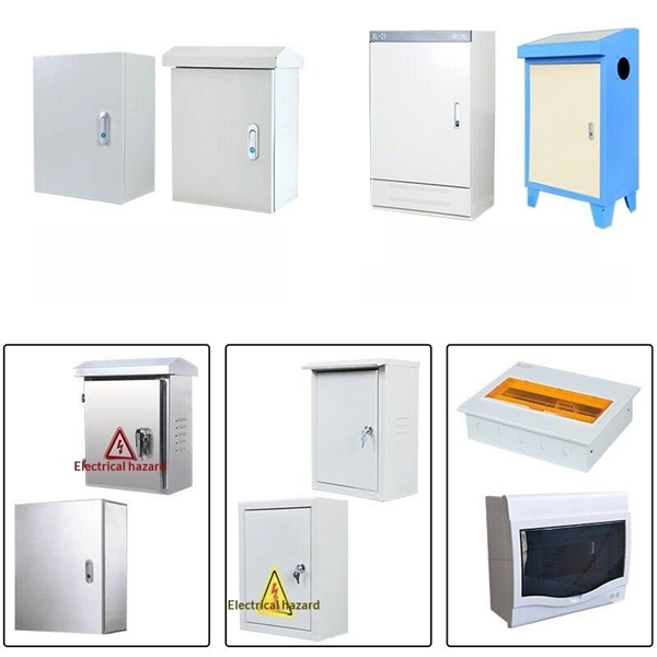
Find Brazilian high low voltage electrical apparatus importers on ExportHub. How does 6Wresearch market report help businesses in making strategic decisions? 6Wresearch actively monitors the Brazil Electric Power Transmission & Distribution Equipment Market and publishes its comprehensive annual report, highlighting emerging trends, growth drivers, revenue analysis, and. The Impact of COVID-19 is included in the Electric Transmission and Distribution Equipment Market in Brazil. Buy it today to get an advantage. The future of the electric transmission and distribution equipment market in Brazil looks promising with opportunities in the power utilities, residential. Are you a seller? Add your own products to Allbiz as well!. Find Brazilian high low voltage electrical apparatus importers on ExportHub. Global Brazil High and Low Voltage Cabinet Market Size, Strategic Opportunities & Forecast (2026-2033) Market size (2024): USD 7. 5 billion · Forecast (2033): USD 10. 2% Brazil High and Low Voltage Cabinet Market Growth Matrix: Drivers, Limitations & Opportunity Landscape Major. 44 comprehensive market analysis studies and research reports on the Brazil Power Transmission and Distribution sector, offering an overview with historical data since 2019 and forecasts up to 2030. This includes a detailed market research of 770 companies, enriched with industry statistics.
[PDF]