In this video, we'll walk you through the process of wiring a home distribution box with a detailed connection diagram. Whether you're an electrician or a DIY enthusiast, this guide will help you understand the basics of home electrical distribution. What is Distribution Board? Distribution board. An electrical panel box, also known as a breaker box or a distribution board, is a crucial component of any electrical system. It serves as a central hub for distributing electricity throughout a building, ensuring that power is delivered safely and efficiently to all the required locations. This panel routes power from the utility service to every circuit while housing circuit breakers that provide overcurrent protection. Installing or replacing a load center is a complex task involving. Always begin with disconnecting the main supply before accessing any enclosure containing distribution components. This prevents arc faults and ensures safety when modifying or inspecting current paths. Inside the service housing, line conductors from the utility feed typically enter through the.
[PDF]
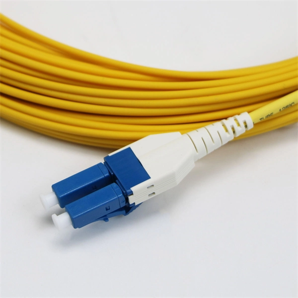
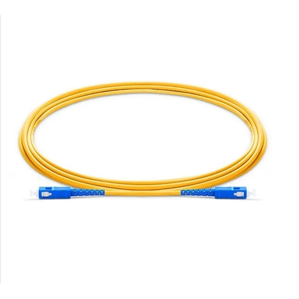
OPGW (Optical Ground Wire) is a kind of cable that comprises the dual functions of grounding and fiber optic communication. It is increasingly utilized in high-voltage transmission lines as a functional element that both safeguards the power system and allows data sharing. OPGW cable in transmission line systems is a unique hybrid solution that combines the functions of grounding and communication into one efficient design. It typically consists of optical fibers encased within an aluminum or steel wire, providing both strength and data transmission capabilities. Enter Optical Power Ground Wire (OPGW) cables 1 —a technology that addresses these needs in a single, integrated solution. As someone who has spent years in the optical communications industry, I've witnessed firsthand how OPGW cables have transformed the landscape of power and telecommunication. An optical ground wire (also known as an OPGW or, in the IEEE standard, an optical fiber composite overhead ground wire) is a type of cable that is used in overhead power lines. An OPGW cable contains a tubular structure with. OPGW is primarily used by the electric utility industry, placed in the secure topmost position of the transmission line where it “shields” the all-important conductors from lightning while providing a telecommunications path for internal as well as third party communications. This guide explores its design, advantages, and applications in modern energy and telecom.
[PDF]
In this video, we'll walk you through the process of wiring a home distribution box with a detailed connection diagram. Whether you're an electrician or a DIY enthusiast, this guide will help you understand the basics of home electrical distribution. more Welcome to our. An electrical panel box, also known as a breaker box or a distribution board, is a crucial component of any electrical system. It serves as a central hub for distributing electricity throughout a building, ensuring that power is delivered safely and efficiently to all the required locations. Follow this guide for a clear and safe connection process: Before starting, always ensure the main power is turned off to avoid electrical shock. Covers wiring, placement, standards, and expert tips for a compliant setup. It takes the incoming power and safely distributes it to different circuits throughout your building. This panel routes power from the utility service to every circuit while housing circuit breakers that provide overcurrent protection. What is Distribution Board? Distribution board.
[PDF]
It is recommended to use tinned copper stranded wire with a minimum cross-sectional area of 4mm² for bridging, with tinned copper lugs crimped at both ends. Iron bolts welded at both ends of the cable troughs can rust and increase contact resistance. Cable tray may be used as the Equipment Grounding Conductor (EGC) in any installation where qualified persons will service the installed cable tray system. The metal in cable trays may be used as the EGC as per the limitations. Standard splice plates can often provide a safe electrical path if they are UL Classified and bolted tight. However, you must use copper bonding jumpers if the tray is painted or has expansion joints for movement. A. Cable tray wiring systems have excellent safety and dependability records. The intent of this article is to review grounding practices for cable tray. Snap Track Cable Tray Can be used as an Equipment Ground Conductor (EGC) Snap Track cable tray is UL Classified, marked with the available minimum cross sectional area and meets all requirements for use as an Equipment Ground Conductor per NEC Article 392. Standard Snap Track splices, tee's. What is best practice for terminating the ground wires within tray cable? Especially when you have a parallel tray cable feeder? For example: A parallel tray cable feeder is installed in cable tray to a 400 amp distribution panel.
[PDF]
Your breaker box wiring includes three main wire types: black hot wires carry electricity to outlets, white neutral wires return unused power, and green ground wires prevent electrocution. The goal is to distribute circuits evenly across both L1 and L2 to keep things balanced and prevent any traydropping electrical mishaps! Now, what happens when you need more power than a single 120V line can deliver? That's where splitphase power comes in. When a circuit connects L1 to L2 (instead. A distribution board or distribution box is where the main power supply is distributed to multiple loads. And all the switching and protective devices are installed in the distribution box. Single Phase Distribution Box generally consists of Double Pole MCBs, Single Pole MCBs, and RCCBs. Wiring – Includes live, neutral, and earth wires for power distribution. Circuit Breakers – Protect the system from overloads and short circuits. Electrical switchboards can have different setups based on their. The neutral wire carries the electricity back to the power source. It completes the circuit by directing the current to a ground or busbar, normally located at the electrical panel. Once the power is “used” at the demand point, it carries it back to the panel. Note: Read my Article on 5KW Solar System Installation, you can do it yourself. Its a complete Guide. It is typically colored black, red, or another color designated for live wires.
[PDF]
Cable trays are used as an alternative to open wiring or electrical conduit systems, and are commonly used for cable management in commercial and industrial construction. In the electrical wiring of buildings, a cable tray system is used to support insulated electrical cables used for power distribution, control, and communication. Today, electrical cable trays have become an essential component in industrial and commercial construction, providing a quick, economical, and. -piece tray istypically used in applications where visual esthetics are important. It is used in a range of applications with sp nch runs from the main cable tray system to electr cal devices or other equipment. It is available with a ventilated or solid bottom. Channel tray can protect against. Cable trays support cable across open spans in the same manner that roadway bridges support traffic. Cable trays are not raceways, and are treated as a structural component of a facility's electrical system. A bridge is a structure that provides safe passage for traffic across open spans. The National Electrical Code publishes the standards for all.
[PDF]
Grounding in cable trays allows electrical leakage from the outer surfaces of the conductors to be channeled into the tray. It helps to safely direct dangerous currents that may result from electrical faults to the ground. Cable tray may be used as the Equipment Grounding Conductor (EGC) in any installation where qualified persons will service the installed cable tray system. There is no restriction as to where the cable tray system is installed. The metal in cable trays may be used as the EGC as per the limitations. Enhanced safety: Grounding provides a safe path for fault currents to flow, significantly reducing the risk of electric shock to personnel and preventing damage to equipment due to overvoltage or insulation failure. It also safeguards against fire hazards caused by excessive heat generated during. that system to lose its UL Classification. If you take what UL states literally, ANY cut to tray (ladder or wi e) would cause a loss of UL Classification. The methods and materials used may vary depending on the structure of the installation. However, the main principle should always be to ensure safe and effective grounding. These systems provide an efficient and adaptable solution for managing a wide range of cables, including power cables, control cables, Ethernet, and fiber optic lines. The flexibility and scalability of cable trays make them an ideal choice for environments where cable density and organization can.
[PDF]
Ungrounded: There is no intentional ground applied to the system-however it's grounded through natural capacitance. Reactance Grounded: Total system capacitance is cancelled by equal inductance. This decreases the current at the fault and limits voltage across the arc at the. In electrical engineering, a protective relay is a relay device designed to trip a circuit breaker when a fault is detected. : 4 The first protective relays were electromagnetic devices, relying on coils operating on moving parts to provide detection of abnormal operating conditions such as. To attain the desired reliability, the power system network is divided into two different protection zones. They are generator protection, transformer protection, bus protection, transmission line protection and feeder. Recognized under 2(f) and 12 (B) of UGC ACT 1956 (Affiliated to JNTUH, Hyderabad, Approved by AICTE - Accredited by NBA & NAAC – 'A' Grade - ISO 9001:2015 Certified) Maisammaguda, Dhulapally (Post Via. Kompally), Secunderabad – 500100, Telangana State, India To introduce all kinds of circuit. A protection relay is a crucial component of electrical systems that safeguard infrastructure, employees, and equipment from electric problems and malfunctions. It functions as a watchdog by constantly surveying multiple system components including voltage, current, frequency, and phase angle.
[PDF]
National Electrical Code (NEC) allows up to three grounding conductors to terminate under one lug on a grounding bus, provided it is listed for such use. This is covered under section 110. Correct grounding of services depends upon understanding the definition and role of the grounded conductor. The neutral conductor is typically the grounded conductor connected to the system's neutral point, carrying current under normal operation. Grounding electrode conductors must be connected at. Sometimes if I have a 3 or 4-gang plastic nail-on switch box that has a bunch of NM cables, when I'm making up the box rather than using a big blue wire-nut for my grounds I'll separate the grounds into 2 groups and use red/tan wirenuts instead, especially if there's 2 circuits in the box. This configuration may not comply with current electrical. Learn how to connect equipment grounding conductors to receptacles and keep their continuity in boxes. The basic rule achieves this through an equipment grounding jumper; four exceptions. A grounding terminal or grounding-type device on a receptacle, cord connector, or attachment plug may not be used for purposes other than grounding. (b) Branch circuits — (1) Identification of multiwire branch circuits. When conductors are spliced inside a box or terminated to.
[PDF]
Cable tray grounding wire is the safety connection that links your electrical system's cable tray to the ground. This provides a safe path for any stray electrical currents to flow safely into the earth, avoiding damage to your equipment and reducing the risk of electric shocks. There is no restriction as to where the cable tray system is installed. The metal in cable trays may be used as the EGC as per the limitations. Cable tray may be used as the Equipment Grounding Conductor (EGC) in any installation where qualified persons will service the installed cable tray system. Consider it as an emergency electricity exit. The main purpose of. Grounding in cable trays is an important practice to increase electrical safety and prevent hazards in case of faults. The methods and materials used may vary depending on the structure of the installation. However, the main principle should always be to ensure safe and effective grounding. It involves connecting cable trays to the facility's grounding system, providing a low-impedance path for fault currents and protecting personnel.
[PDF]