This research report provides a comprehensive analysis of the Passive Optical Components market, focusing on the current trends, market dynamics, and future prospects. How does 6W market outlook report help businesses in making decisions? 6W monitors the market across 60+ countries Globally, publishing an annual market outlook report that analyses trends, key drivers, Size, Volume, Revenue, opportunities, and market segments. 22 USD Billion in 2024. The Passive Optical Component industry is projected to grow from 17. 01 USD Billion by 2035, exhibiting a compound annual growth rate (CAGR) of 6. 8% during the forecast period. Passive Optical Components are critical elements in fiber optic. Global passive optical component market is estimated to be valued at US$ 86. 2% from 2026 to 2033. Discover market dynamics shaping the industry: Download Free Sample Global passive. The Global Passive Optical Components Market was valued at USD 38. These components play a crucial role in the transmission of data, voice, and video signals over optical networks. The market for passive optical.
[PDF]
pigtails can be divided into single-mode (colored yellow) and multimode (colored orange) fiber. Multimode pigtails use 62.5/125 micron or 50/125 micron bulk multimode fiber cables and terminated them with multimode fiber optic c. pigtails can be divided into single-mode (colored yellow) and multimode (colored orange) fiber. Multimode pigtails use 62.5/125 micron or 50/125 micron bulk multimode fiber cables and terminated them with multimode fiber optic connectors at one end. 10G multimode fiber cables (OM3 or OM4) are also available in optic pigtails. The jacket color of 10. Fiber Optic Pigtails, In fiber optic cable installation, how cables are attached to the system is vital to the success of network. If done properly, optical signals would pass through the link with low attenuation and little return loss. pigtail offers an optimal way to joint optical fiber, which is used in 99% of single-mode applications. This pos. According to different types of pigtail cable connector terminated at the end, there are LC fiber pigtail, SC pigtail, ST pigtail, FC pigtail, fiber pigtail and so on. With different structures and appearance, each of them has their own advantages in different applications and systems. Let's go through some widely used ones. SC Pigtail: SC pigtail.
[PDF]
At the heart of every optical transceiver lie three essential components, often called the “Three Pillars” of optical communication: Laser — generates light. Modulator — encodes data onto the light. Photodiode — decodes light signals back into electrical form. As an essential component of optical fiber communication, optical modules are optoelectronic devices that facilitate the conversion between optical and electrical signals during the transmission process. Operating at the physical layer of the OSI model, optical modules are core devices in optical. An optical module usually consists of an optical transmitting device (TOSA, including a laser), an optical receiving device (ROSA, including a photodetector), functional circuits,main control circuit board (PCBA), housing and optical (electrical) interface and other components. Together, lasers, modulators, and. That is, metal medium communication represented by coaxial cables and network cables is gradually being replaced by optical fiber media. Composition of Optical Modules The optical module, known as Optical Transceiver in. This comprehensive guide breaks down the internal structure, core components (TOSA, ROSA, lasers), and operational mechanisms of SFP optical modules, enriched with technical insights and real-world applications. These modules typically consist of a transmitter, which converts electrical signals into a light signal, and a receiver, which converts the received signal back.
[PDF]
Diode lasers are compact, solid-state devices that generate coherent light from semiconductor material. They are constructed using materials like gallium arsenide (GaAs) or gallium nitride (GaN). SEM (scanning electron microscope) image of a commercial laser diode with its case and window cut away. The anode connection on the right has been accidentally broken by the case cut process. They operate by applying an electrical current to the semiconductor material, which stimulates the. What is a Laser Diode? A laser diode is a small, solid-state equipment that uses semiconductor material to produce continuous light. The laser can be made up of a single diode or a combination. Laser diodes come in various types, each suited for specific applications. The most common types include: Single-Mode Laser Diodes: Emit a single wavelength of light, ideal for high-precision tasks. VCSEL. The laser diode is a form of semiconductor diode that generates coherent laser light rather than the more usual incoherent light produced by other sources such as LEDs or other emitters, even though some of these produce a narrow band of frequencies. Semiconductor laser diode technology is in. The term LASER stands for Light Amplification by Stimulated Emission of Radiation. It functions similarly to an LED, but the key.
[PDF]
Ungrounded: There is no intentional ground applied to the system-however it's grounded through natural capacitance. Reactance Grounded: Total system capacitance is cancelled by equal inductance. This decreases the current at the fault and limits voltage across the arc at the. In electrical engineering, a protective relay is a relay device designed to trip a circuit breaker when a fault is detected. : 4 The first protective relays were electromagnetic devices, relying on coils operating on moving parts to provide detection of abnormal operating conditions such as. To attain the desired reliability, the power system network is divided into two different protection zones. They are generator protection, transformer protection, bus protection, transmission line protection and feeder. Recognized under 2(f) and 12 (B) of UGC ACT 1956 (Affiliated to JNTUH, Hyderabad, Approved by AICTE - Accredited by NBA & NAAC – 'A' Grade - ISO 9001:2015 Certified) Maisammaguda, Dhulapally (Post Via. Kompally), Secunderabad – 500100, Telangana State, India To introduce all kinds of circuit. A protection relay is a crucial component of electrical systems that safeguard infrastructure, employees, and equipment from electric problems and malfunctions. It functions as a watchdog by constantly surveying multiple system components including voltage, current, frequency, and phase angle.
[PDF]
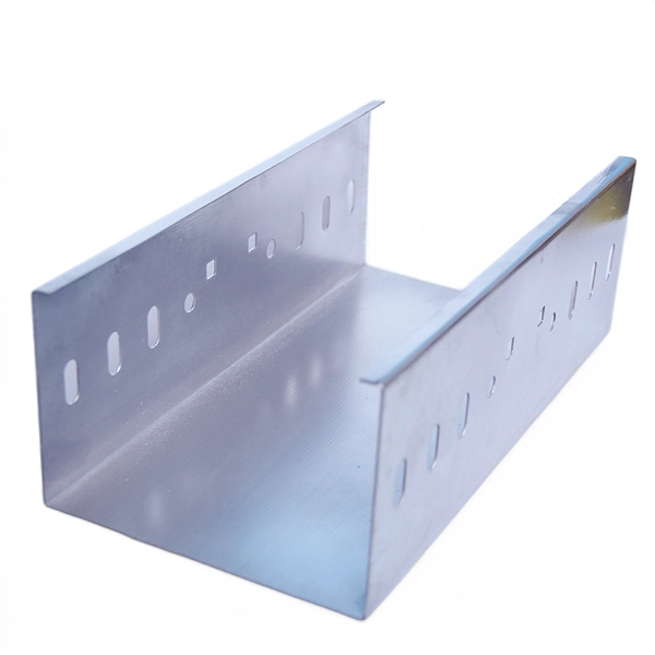
Cable tray grounding wire is the safety connection that links your electrical system's cable tray to the ground. This provides a safe path for any stray electrical currents to flow safely into the earth, avoiding damage to your equipment and reducing the risk of electric shocks. There is no restriction as to where the cable tray system is installed. The metal in cable trays may be used as the EGC as per the limitations. Cable tray may be used as the Equipment Grounding Conductor (EGC) in any installation where qualified persons will service the installed cable tray system. Consider it as an emergency electricity exit. The main purpose of. Grounding in cable trays is an important practice to increase electrical safety and prevent hazards in case of faults. The methods and materials used may vary depending on the structure of the installation. However, the main principle should always be to ensure safe and effective grounding. It involves connecting cable trays to the facility's grounding system, providing a low-impedance path for fault currents and protecting personnel.
[PDF]
NEC (National Electrical Code) Article 800 covers the general requirements for communications systems, including wiring methods, grounding, fire resistance, and installation practices for cables and equipment. The term “cable” means stranded conductor or a combination of conductors that includes Fiber Optic Supply Cable, Fiber Optic Communication Cable, or Non–Dielectric Fiber Optic Cable as defined in Rule 20. The term “messenger” is defined in Rule 22. The. This Applications Engineering Note (AE Note) discusses conventional bonding and grounding practices for conductive fiber optic cable and hardware installations within the scope of the National Electrical Code (NEC). This AE Note does not address outside plant fiber optic installations or. ned herein and with other Sections of this Specification as applicable to the completion of the installation. It applies to circuits that extend from the communications utility (such as telephone or. Article 800”General Requirements for Communications Systems covers general requirements for installing communications circuits, community antenna television and radio distribution systems, network-powered broadband communications systems, and premises-powered broadband communications systems. to n utral comm.
[PDF]