By combining compact laser sources with sub-1 ml volume and ultrastable optical cavities, this work enables extremely compact and robust ultrastable laser systems with applications in low phase noise microwave generation, sensing, and satellite ranging. The Laser Light Screen System faces critical technical challenges in high-speed, long-range target detection: when a target passes through the light screen, weak light flux variations lead to significantly degraded signal-to-noise ratios (SNRs). Traditional signal processing algorithms fail to. Ultra-low-noise microwave signals play a driving role in the development of modern scientific technologies such as radar, communication, and sensing. On-chip photonic integration provides an attractive approach for the implementation of ultra-low-noise microwave signal sources with attractive added. We demonstrate thermal-noise-limited direct locking of a semiconductor distributed feedback (DFB) laser to a sub-1 mL volume, ultrastable optical cavity, enabling extremely compact and simple ultrastable laser systems. Using the optoelectronic laser locking method, we realize over 140 dB. Here we address these shortcomings with a hybrid optoelectronic approach that combines simplified optical frequency division with direct digital synthesis to produce tunable low-phase-noise microwaves across the entire X-band (8–12 GHz). Traditional signal processing algorithms.
[PDF]
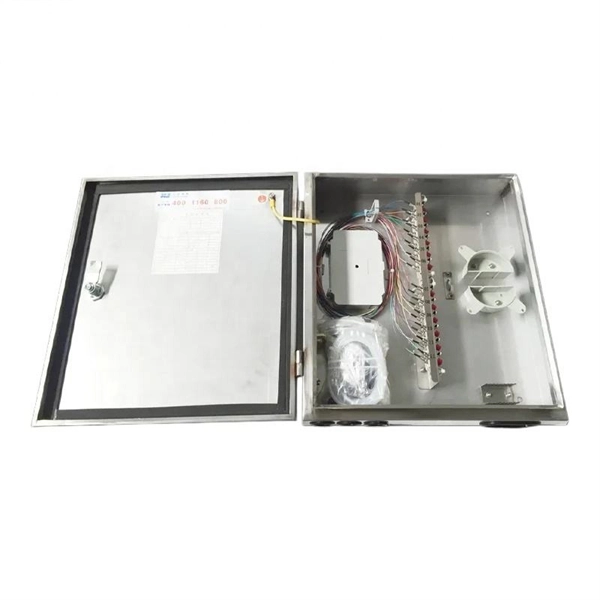
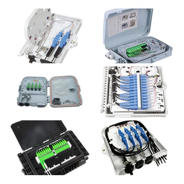
Join our mailing list and receive free updates every month! 24 Core IP68 Splice Enclosure with 2 x 12 Way Splice Trays (185 x 260 x 70) 2 ports in 2 ports out If you require a bespoke product please click here to contact us with your requirements for a quote. CD-24F-FS-W 24 Fibers Splice Tray provides secure organization and protection for up to 24 fusion splices, ensuring reliable performance in FTTx, data center, and enterprise networks. Its compact capacity and stackable design make it ideal for small-scale or distributed fiber management. These fiber splice trays, adapter panels and cable fan-out kits can accept up to 24 fibers. Made by AFL, Corning, Leviton, Pandit and other manufacturers. RLH Industries Outside Plant Fiber Splice Closure provides reliable and flexible installation for outdoor applications. The compact size and high quality construction allow for installation in both underground and aerial environments. The case lid is hinged for correct alignment and is secured with. Check each product page for other buying options. Price and other details may vary based on product size and color. Need help?. ZIP code to view pricing. ZIP code to. Whether you need fusion splicing for permanent, ultra-low-loss connections or mechanical splicing for rapid field deployment, our certified technicians deliver factory-quality results on every job — from hyperscale data centers and carrier-grade telecom networks to enterprise campus infrastructure.
[PDF]
It supports a maximum of 10 x double-width GPU cards, 4 x standard PCIe cards, and 3 x OCP NICs, and provides ultra-large capacity or ultra-fast storage through 24 x 3. 5" drives or 12 x NVMe SSDs. FusionServer G5500 V6 Server Technical White Paper Contents Contents About This Document. v 1 Product Overview. 13 5 Hardware. • FusionServer G5500 V7 (G5500 V7) is a new-generation 4U 2-socket AI server. • G5500 V7 features high. The advantages of deploying DeepSeek-R1-70B large model on the G5500 V6 AI server for super fusion fusion fusion - Sell Dell/Xfusion/Huawei server,From China. Page 2 Actually, the information of each Restriction vendor on the network is incomplete or may not be up-to-date. In addition, Huawei may update this course Scenario without notifying the customer. Page 3. I built and tested a general-purpose MCP AddIn for Fusion which I suspect has great potential in future; it's a careful architecture which generically exposes all API internals to the AI, no limits, making it possible to help with anything and everything you might ever need. If anyone's interested.
[PDF]
You simply multiply the number of splices by the estimated loss per splice. It's that easy! ✨ Let's say you have a long fiber run that requires 4 fusion splices to connect different cable segments. 4 dB is the total attenuation you'll add to your loss budget just for the. Fusion splicing is the process of fusing or welding two fibers together usually by an electric arc. Fusion splicing is the most widely used method of splicing as it provides for the lowest loss and least reflectance, as well as providing the strongest and most reliable joint between two fibers. There are several ways to know the number of multi-spliced cores. For example, 12 core fibers, 12*2=24 cores, 12 cores at the beginning and 12 cores at the end; 2. Count the number of optical fiber. Calculating the total loss from splices in a cable run is wonderfully straightforward. Connectors: Total number of connectors in design. Laser: A device which produces a single frequency light. The guide provides the complete workflow, covering safety precautions, tool selection, fiber preparation, fusion operation, quality control, and. Recommendation ITU-T L. 12 specifies splices of single-mode and multimode optical fibres. It describes suitable procedures for splicing that should be carefully followed in order to obtain reliable splices between single optical fibres or ribbons.
[PDF]
A fusion splicer is a specialized device used to join two optical fibers end-to-end through the process of fusion. By aligning the fibers precisely and applying a controlled electric arc, the fusion splicer melts the ends of the fibers, creating a single, continuous fiber. Fusion splicers are essential for creating low-loss, high-performance fiber optic connections in telecom, FTTH, and data center applications. The best splicers offer core alignment, fast splice times, durable designs, and smart features like cloud syncing and automated calibration. This process minimizes. Fiber splicing is the process of permanently joining two fibers together. Unlike fiber connectors, which are designed for easy reconfiguration on cross-connect or patch panels. There are two types of fiber splicing – mechanical splicing and fusion splicing. It is the technique that has the least insertion loss and almost no back reflection, hence ensuring strong connections over a long period. Fiber optic splicers are.
[PDF]
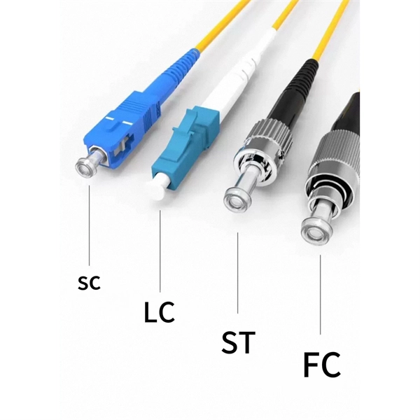
This guide covers everything: what fiber optic pigtails are, how they differ from patch cords, which connector and polish type to specify, how to choose between mechanical and fusion splicing, and the real-world applications where pigtails are the right call. This article compares fusion splicing and pre-terminated solutions on these terms, and reviews what's required in a hyperscale ODF in order to scale up to 5,000+ connections in a single frame. Fusion splicing vs connectorization: what's the best choice for a hyperscale ODF? The physics and. Fiber optic joints or terminations are made two ways: 1) splices which create a permanent joint between the two fibers or 2) connectors that mate two fibers to create a temporary joint and/or connect the fiber to a piece of network gear. Either joining method must have three primary characteristics. There are two primary techniques for terminating fiber optic cables: Splicing: Joining two fiber optic cables permanently. Connectors: Attaching removable connectors for quick and flexible connections. Fiber splicing is the process of permanently joining two optical fibers end-to-end. This blog will delve into the nuances of each method, comparing their costs, labor efficiency, network performance, and more, to help you decide which splicing technique is best suited for your needs. Fusion splicing involves heating the fiber ends and fusing them together, while mechanical splicing uses tubes, V-grooves, or other guides to.
[PDF]
This guide reveals the secrets to fusion splicing with little fluff—just proven, straightforward techniques refined from years of work in the field. In this guide, you will find a chronological description of the fusion splicing process, the principal technical standards, and answers to the real-life questions network engineers and procurement teams may have. The guide provides the complete workflow, covering safety precautions, tool selection, fiber preparation, fusion operation, quality control, and. Summary: Fiber color codes, defined by the TIA-598-C standard, help technicians quickly identify individual fibers, buffer tubes, and connectors in multi-strand cables. Using proper color coding makes installation easier, speeds up troubleshooting, reduces downtime, and supports future network. When a tech opens a fiber optic cable to prepare it for splicing, they will find a colorful bundle of buffer tubes as on this armored cable. The colors of the buffer tubes and likewise the fibers in the tubes provide the identification the tech needs to complete the splicing of the fibers as the. Fusion splicing is the bedrock of high-performance fiber optic networks, enabling seamless signal transmission through permanent, low-loss fiber joins. By adopting the TIA/EIA‑598C standard, you gain a universal “language” of colors that speeds identification, reduces miswiring, and enhances safety.
[PDF]