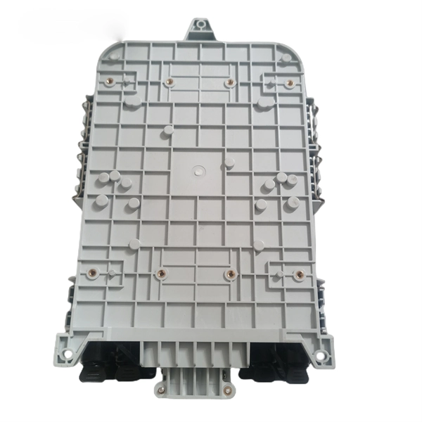
Join our mailing list and receive free updates every month! 24 Core IP68 Splice Enclosure with 2 x 12 Way Splice Trays (185 x 260 x 70) 2 ports in 2 ports out If you require a bespoke product please click here to contact us with your requirements for a quote. CD-24F-FS-W 24 Fibers Splice Tray provides secure organization and protection for up to 24 fusion splices, ensuring reliable performance in FTTx, data center, and enterprise networks. Its compact capacity and stackable design make it ideal for small-scale or distributed fiber management. These fiber splice trays, adapter panels and cable fan-out kits can accept up to 24 fibers. Made by AFL, Corning, Leviton, Pandit and other manufacturers. RLH Industries Outside Plant Fiber Splice Closure provides reliable and flexible installation for outdoor applications. The compact size and high quality construction allow for installation in both underground and aerial environments. The case lid is hinged for correct alignment and is secured with. Check each product page for other buying options. Price and other details may vary based on product size and color. Need help?. ZIP code to view pricing. ZIP code to. Whether you need fusion splicing for permanent, ultra-low-loss connections or mechanical splicing for rapid field deployment, our certified technicians deliver factory-quality results on every job — from hyperscale data centers and carrier-grade telecom networks to enterprise campus infrastructure.
[PDF]
Positive busbars, which collect all positive connections. Key Steps: When wiring a pair of 12V busbars, connect the positive terminal of each load to a stud on the positive busbar and their negative terminal to a stud on the negative busbar. 5' above batteries on inside of cockpit combing below decks. Install one new positive bus bar beside the negative one separated by about two inches 3. Positive and negative busbars are physically identical apart from the red/black colours used by some manufacturers to visually differentiate between. A Complete Guide to Battery Terminal Connector Types The store will not work correctly in the case when cookies are disabled. JavaScript seems to be disabled in your browser. For the best experience on our site, be sure to turn on Javascript in your browser. Skip to Content Blog Sign In Create an. This image illustrates a standard car battery with top post terminals and labeled connectors for the positive (+) and negative (–) ends, emphasizing safe and correct installation. A battery terminal connector is a fitting or clamp that attaches to a battery's terminal to connect a cable. In other. Both positive and negative terminals are the soul of the electrical system of the car, allowing the engine to start while keeping other components running. The catch? Mix-up or loose connection can cause electrical failure, drained batteries, and damage to wiring. This blog guides you how the two.
[PDF]
A fiber optic pigtail is a short length of optical fiber cable with a factory-terminated connector on one end and a bare, exposed fiber on the other. Executive Summary: A fiber optic pigtail is one of the most commonly specified yet least understood components in structured cabling. Get the wrong connector type, the wrong polish, or skip proper fusion splicing technique—and you're looking at elevated signal loss, increased back reflection, and a. According to Cambridge Dictionary, to splice means to “join the ends of something so that they become one piece. ” So in essence, fiber optic splicing is a process used to join two separate fiber optic cables together. There are numerous use cases for fiber optic splicing. Through splicing, fiber. Fiber optic joints or terminations are made two ways: 1) splices which create a permanent joint between the two fibers or 2) connectors that mate two fibers to create a temporary joint and/or connect the fiber to a piece of network gear. Either joining method must have three primary characteristics. Splicing allows you to restore or expand fiber networks while maintaining signal integrity. When done right, splicing ensures minimal loss and long-lasting performance. These terminations must be of the right style, installed in a.
[PDF]
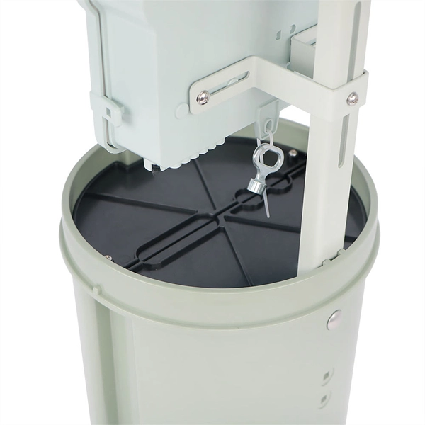
Fiber splice closures are not used occasionally — they are deployed extensively across every fiber network. The exact quantity depends on population density, network topology, and regional infrastructure planning. There are hundreds of different designs and options on splice closures. Some are designed for concatenation of long distance cables where two identical cables are spliced together. Its role is not only to enclose the splice, but to ensure that optical performance remains stable throughout years of operation. In FTTX and outdoor access networks especially, the reliability of. There are several types of fiber optic splice closures available in the market, each designed for specific applications and environments. There are many possible ways to put two or more cables together or drop a single fiber at a location. It creates an air-tight environment that safeguards these splices from environmental considerations, including wetness, dust, and temperature changes; hence, the. CommScope addresses these challenges with a comprehensive family of fiber splice closures that prioritize essential criteria: reliability, installability, flexibility, and speed of deployment. Trunk and Feeder Network Solutions: These closures are designed for robust performance in the backbone of.
[PDF]
Passive media components such as cables, cable splices, and connectors cause attenuation. Although attenuation is significantly lower for optical fiber than for other media, it still occurs in both multimode and single-mode transmissions. Two fundamental mechanisms cause attenuation inside the fiber itself: absorption and scattering. These are intrinsic to the glass, meaning they exist even in a perfectly manufactured, perfectly installed fiber. Scattering is the bigger factor at the wavelengths most networks use. The silica glass. Optical attenuation is the gradual loss of flux (light intensity) as an optical signal travels through a fiber. Measured in decibels (dB), it's the logarithmic ratio of the output power to the input power. Every network has a "loss budget". F iber optic networks rely on the efficient transmission of light signals to deliver high-speed data over long distances. However, various factors can cause signal degradation, leading to performance issues and reduced network reliability. You may see slower speeds and less steady connections when signal loss goes up. Things like impurities in the fiber core and reflections at the core-cladding edge cause this drop. This can be due to a variety of factors: scattering and absorption, intrinsic. Signal attenuation in fiber optics is a key concept in telecommunications. It affects how far a signal can travel without losing.
[PDF]
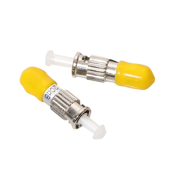
The simplest method: connect two cables pre-connectorized via a coupler (also called an adapter). The coupler aligns the two ferrules of the connectors using a zirconia sleeve. Why connect two fibers? Do you need to extend, repair, or connect two fiber optic cables? There are three methods main ones, each with its advantages and limitations. This article explains when. Optical fiber fast connectors, also known as cold connectors, are becoming increasingly popular due to their ease of use and quick installation. Unlike traditional fiber connectors that require epoxy and polishing, fast connectors use a mechanical splice to join the fibers. Another method is using a mechanical splice which involves aligning and securing the fiber ends with a precision. Fiber optic cables can be connected together using a couple of different methods: 1. This creates a permanent and low-loss connection. Connectors play a crucial role in our daily lives, yet there are some connectors that remain less familiar, such as fiber optic fast connectors. The goal is clean.
[PDF]
EIA/TIA 568 B allows any fiber optic connector as long as it has a FOCIS (Fiber Optic Connector Intermateability Standard) document behind it. Fiber optic cold connection, also known as mechanical splicing, is a widely used method of connecting optical fibers in a network. Unlike fusion splicing, which uses heat to join two optical fibers together, cold connection uses mechanical means to create a stable and low-loss connection. Unlike fiber splicing, which is permanent, connectors allow for easy connection and disconnection of cables, making them ideal for maintenance and flexibility in. Fiber optic joints or terminations are made two ways: 1) splices which create a permanent joint between the two fibers or 2) connectors that mate two fibers to create a temporary joint and/or connect the fiber to a piece of network gear. These terminations must be of the right style, installed in a. Fiber termination refers to the process of preparing the end of a fiber optic cable to connect to another fiber, a device, or a network. Proper termination is essential for ensuring optimal performance, reducing signal loss, and maintaining the durability of the connection. Since the introduction of fiber optic technology decades ago, a variety of connector types have been.
[PDF]

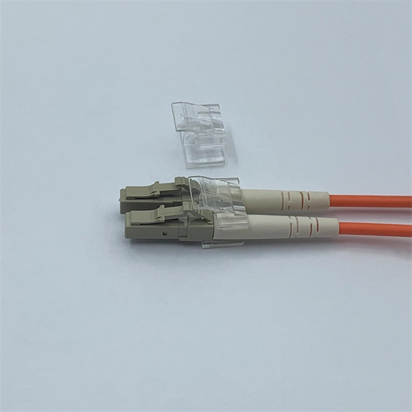
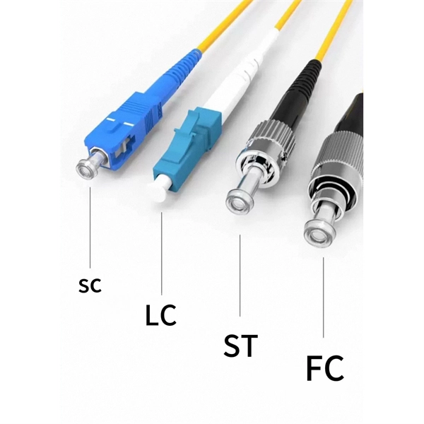
In this guide, we'll walk you through the entire process of preparing fiber optic cable for splicing and termination to fiber connectors. We'll explore the necessary tools, safety precautions, and step-by-step procedures for cable connectors, mechanical and. This article will guide you through the necessary tools, materials, and methods on how to connect fiber optic cables effectively, ensuring you achieve optimal performance from your fiber optic network. Have a network installation project? Fiber Optic Cables: The primary medium for your connections. There are many types of fiber optic connectors, including SC, LC, FC, ST, D4, MU, MT/MPO, etc. These connectors can be divided into single-mode and multi-mode fiber optic connectors according to their structure and purpose. Fiber optic connectors play an essential role in the realm of optical communication, enabling seamless connections between fiber optic cables. At the heart of any robust fiber optic network lies a crucial process: Preparing a fiber cable for termination of a connector or splice. Whether you're installing a new network, expanding an existing one, or. Fiber optic internet delivers blazing-fast speeds and reliable connectivity, making it a top choice for modern homes and businesses.
[PDF]
This report is a detailed and comprehensive analysis for global E2000 Connectors market. Both quantitative and qualitative analyses are presented by manufacturers, by region & country, by Type and by Application. Find advanced e2000 apc connector answers for quick and dependable data flow. Use modern technologies to improve connection for flawless communication. According to our (Global Info Research) latest study, the global E2000 Connectors market size was valued at US$ 191 million in 2024 and is forecast to a readjusted size of USD 318 million by 2031 with a CAGR of 7. 4% during review period. In this report, we will assess the current U. tariff. There are single mode E2000 UPC connector, single mode E2000 APC connector and multimode E2000 UPC connectors, and there are adapters to use with them accordingly. E2000 products include simplex and duplex versions. The E-2000 Connector Series is one of the few fiber optic connectors featuring a. E-2000® is an optical fiber plug connector, available for both single mode and multi-mode applications, featuring a spring-loaded shutter and dust-cap. Read More The connector lever is a durable, high-quality locking component designed specifically for SENKO E-2. It is widely used in data centers, telecommunications, and industrial networking due to its.
[PDF]
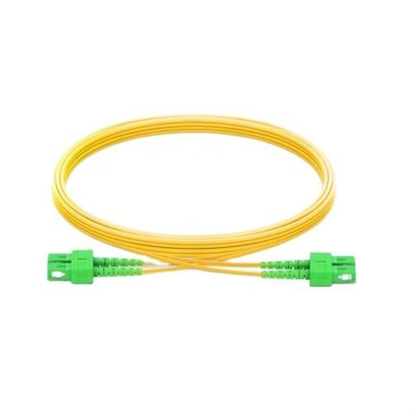
Learn how to choose the right fiber patch cord supplier by comparing price vs. quality, certifications, and delivery reliability. Back to Products & Services All Cable Assemblies Cable Assemblies Active Electrical Cable Solutions Active Optical Cables (AOC) AirBorn FOCuS Rugged Active Optical Cables Custom Cable Assembly Solutions Direct Attach Cable (DAC) Assemblies Fiber Optic Cable Assemblies HSAutoLink Interconnect System. Check each product page for other buying options. Need help?. Nano-Giga offers a wide range of fiber optic connectors and patch cords to suit your applications. The quick and professional support we receive from PTspeed ensures we always have what we need, when we need it. They're not just any supplier; they're an online supplier with robust in-stock. The fiber optic cable is used to connect or patch one optical device to another. Each end of the fiber optic cable has a connector that allows the installer to quickly connect or disconnect the cable as needed. They are very convenient. You will find the cable is. This guide will help you understand how to evaluate suppliers and make an informed decision when sourcing fiber optic patch cords for your projects — from FTTH deployments and Data Centers to Industrial Networks and Telecommunications Infrastructures. Tip: Many high-quality fiber patch cord.
[PDF]
Explore a vast selection of robust and reliable connectors at Norwegian Electronic Supply AS. Designed for subsea and marine applications, our connectors ensure optimal performance. High-quality fiber cables, connectors, and assemblies for enterprise and infrastructure networks. Fiber connectivity engineered for shock, vibration, temperature extremes, and demanding field. T&G is a leading manufacturer and distributor of connectivity solutions including cables, harnesses, connectors, fiber optic boards, tools, and accessories. of our DNA and is incuded in everything we do. T&G is certified to EN9100 (AS9100), ISO9001 and ISO14001. our customers' needs. Hos oss finner du alt du trenger til ditt fibernett! Fiberworks is a specialized manufacturer in the fiber optic market, offering a variety of products and services. Several functions. One cable | Smart cable solutions. Our selection also includes Huber+Suhner's portfolio of their self-developed connectors for. The M Series connectors meet the highest standards of safety for deep immersion. It is currently used in many applications: from oil and gas industry service to renewable energy generation system and military submarines. The M Series feature a large range of shell styles, layouts or insulator.
[PDF]
It supports a maximum of 10 x double-width GPU cards, 4 x standard PCIe cards, and 3 x OCP NICs, and provides ultra-large capacity or ultra-fast storage through 24 x 3. 5" drives or 12 x NVMe SSDs. FusionServer G5500 V6 Server Technical White Paper Contents Contents About This Document. v 1 Product Overview. 13 5 Hardware. • FusionServer G5500 V7 (G5500 V7) is a new-generation 4U 2-socket AI server. • G5500 V7 features high. The advantages of deploying DeepSeek-R1-70B large model on the G5500 V6 AI server for super fusion fusion fusion - Sell Dell/Xfusion/Huawei server,From China. Page 2 Actually, the information of each Restriction vendor on the network is incomplete or may not be up-to-date. In addition, Huawei may update this course Scenario without notifying the customer. Page 3. I built and tested a general-purpose MCP AddIn for Fusion which I suspect has great potential in future; it's a careful architecture which generically exposes all API internals to the AI, no limits, making it possible to help with anything and everything you might ever need. If anyone's interested.
[PDF]
You simply multiply the number of splices by the estimated loss per splice. It's that easy! ✨ Let's say you have a long fiber run that requires 4 fusion splices to connect different cable segments. 4 dB is the total attenuation you'll add to your loss budget just for the. Fusion splicing is the process of fusing or welding two fibers together usually by an electric arc. Fusion splicing is the most widely used method of splicing as it provides for the lowest loss and least reflectance, as well as providing the strongest and most reliable joint between two fibers. There are several ways to know the number of multi-spliced cores. For example, 12 core fibers, 12*2=24 cores, 12 cores at the beginning and 12 cores at the end; 2. Count the number of optical fiber. Calculating the total loss from splices in a cable run is wonderfully straightforward. Connectors: Total number of connectors in design. Laser: A device which produces a single frequency light. The guide provides the complete workflow, covering safety precautions, tool selection, fiber preparation, fusion operation, quality control, and. Recommendation ITU-T L. 12 specifies splices of single-mode and multimode optical fibres. It describes suitable procedures for splicing that should be carefully followed in order to obtain reliable splices between single optical fibres or ribbons.
[PDF]
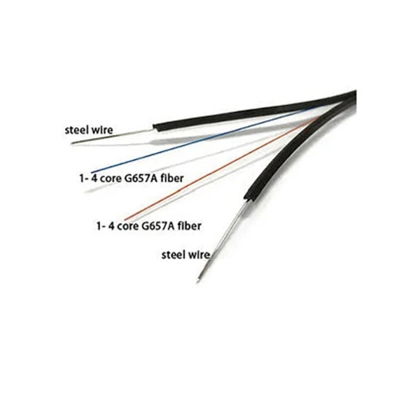
This guide reveals the secrets to fusion splicing with little fluff—just proven, straightforward techniques refined from years of work in the field. In this guide, you will find a chronological description of the fusion splicing process, the principal technical standards, and answers to the real-life questions network engineers and procurement teams may have. The guide provides the complete workflow, covering safety precautions, tool selection, fiber preparation, fusion operation, quality control, and. Summary: Fiber color codes, defined by the TIA-598-C standard, help technicians quickly identify individual fibers, buffer tubes, and connectors in multi-strand cables. Using proper color coding makes installation easier, speeds up troubleshooting, reduces downtime, and supports future network. When a tech opens a fiber optic cable to prepare it for splicing, they will find a colorful bundle of buffer tubes as on this armored cable. The colors of the buffer tubes and likewise the fibers in the tubes provide the identification the tech needs to complete the splicing of the fibers as the. Fusion splicing is the bedrock of high-performance fiber optic networks, enabling seamless signal transmission through permanent, low-loss fiber joins. By adopting the TIA/EIA‑598C standard, you gain a universal “language” of colors that speeds identification, reduces miswiring, and enhances safety.
[PDF]
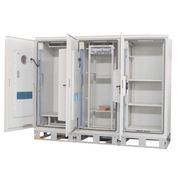
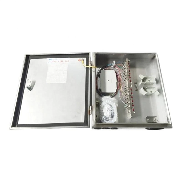
The core principle of fiber optic splicing is to achieve low-loss, high-strength junctions between fiber ends. This involves three key steps: preparation, alignment, and bonding. Let's break it down technically:. At the core of this system's precision and reliability are Fiber Optic Splice Boxes—the unsung heroes that house and protect the delicate junctions where fiber cables are joined. The integrity of these enclosures is paramount to network performance. This guide optimizes the original text by delving. A splice box (also known as splice distributor) is a housing in which fiber optic cables begin or end. Key Functions Typical Applications ZION FTB Highlights In essence: The Fiber Terminal Box is an end-user termination device for small-scale distribution. ■ What Is a Fiber. Fiber optic cables are the lifeline of modern telecommunications, delivering high-speed data with minimal loss. However, installing and maintaining these networks requires seamless connections between fiber segments—a process known as fiber optic splicing. Understanding how it works is essential for anyone interested in telecommunications or network infrastructure. Essential for mending faults or scaling networks, splicing underpins the backbone of contemporary communications. In this comprehensive guide.
[PDF]