If a fault is detected, the relay will send signals to adjacent relays and circuit breakers, allowing the closest breaker to trip first while other breakers delay their operation. This selective coordination helps isolate the faulted zone while maintaining the power supply to the. A protection relay is a crucial component of electrical systems that safeguard infrastructure, employees, and equipment from electric problems and malfunctions. It functions as a watchdog by constantly surveying multiple system components including voltage, current, frequency, and phase angle. It. A protective relay is the vigilant guardian of electrical networks, constantly monitoring and analyzing electrical parameters to detect abnormal events. Acting as the first line of defence, it swiftly detects faults, such as short circuits or overcurrents. It triggers protective actions to isolate. In electrical engineering, a protective relay is a relay device designed to trip a circuit breaker when a fault is detected. : 4 The first protective relays were electromagnetic devices, relying on coils operating on moving parts to provide detection of abnormal operating conditions such as. A protective relay is an intelligent device that senses abnormal electrical conditions, such as overcurrent, under-voltage, or frequency deviations. It initiates the operation of circuit breakers to isolate the affected section.
[PDF]

A protection relay tripping circuit connects relays to breakers for fast fault isolation. Key components include trip/close coils and anti-pumping relays. Proper design, testing, and maintenance ensure reliable overcurrent, differential, and auto-reclosing protection in power. The protection relay tripping circuit refers to the critical electrical control loop that executes trip/close commands from protective relays to circuit breakers, ensuring rapid fault isolation in power systems. Essential. Electromechanical protective relays at a hydroelectric generating plant. The relays are in round glass cases. In electrical engineering, a protective relay is a relay device. A protective relay is an intelligent electrical device designed to detect faults in power systems and initiate corrective actions such as tripping a circuit breaker. Its main purpose is to safeguard electrical equipment like transformers, generators, and transmission lines from damage due to. By definition, a protective relay is a switchgear device that detects faults and initiates the circuit breaker operation to isolate the problematic component of the system. Electrical values are measured by these relays to determine abnormal circumferences of a circuit. It functions as a watchdog by constantly surveying multiple system components including voltage, current, frequency, and phase angle.
[PDF]
LV overhead lines are protected against overcurrents using fuses or circuit breakers. Protection of MV overhead lines is usually achieved by overcurrent relays (50; 50N; 51; 51N; 67; 67N) connected to.
[PDF]
The standard industry practice is to set overload relays at 125% of the motor's nameplate Full Load Ampere (FLA) rating. Plug Setting Multiplier (PSM) indicates how many times the determined relay secondary current (typically the CT secondary) exceeds the relay pickup (plug) current. It is the key quantity utilized in IDMT (inverse definite minimum time) curves to calculate the basic operating time. PSM (Plug Setting. An overload relay is a crucial device for motor control, designed to prevent motors from overheating or suffering winding damage due to excessive current. Motor overload relays protect against sustained overcurrent conditions that cause dangerous overheating, insulation breakdown, and premature. Overload relays protect motors and equipment from thermal damage caused by prolonged overcurrent conditions. IEC 60255 defines standards, formulas, and performance requirements, enabling accurate calculations and real-world applications. How is the overload relay current calculated? Why include. Setting motor overload relays correctly is critical for protecting AC induction motors from sustained overcurrent conditions while avoiding nuisance trips during normal starting transients. This occurred when the relay F was set at 1. The complaint was that the relay tripped instantly on overload when the thermal damage curve show plotted for a specific current that was less t an.
[PDF]
With its novel and future-oriented approach our software solution for system-based protection testing, performs tests independent of relay type, relay manufacturer, and offers extensive parameter settings. It focuses on. With its novel and future-oriented approach our software solution for system-based protection testing, performs tests independent of relay type, relay manufacturer, and offers extensive parameter settings. It focuses on the correct behavior of the protection system by simulating realistic events in the power system. RelaySimTest. Specifically designed for settings-based protection testing with a high degree of automation, our modular software Test Universe offers numerous functions and application-optimized test modules that save you valuable time. Test Universe. Use CMControl P for quick and easy manual testing. CMControl P is available as an App for Android tablets and Windows PC, or as a dedicated front-end device. CMControl P. With this software the CMC test set becomes a multifunctional measurement and recording unit. You can use EnerLyzer in parallel with the software used for operating your CMC. Enerlyzer. The open programming interface CMEngine enables you to integrate the CMC test sets into your own testing environment and control them within any type of application. CMEngine.
[PDF]
In this guide, we'll explore what protection relays are, how they're classified, the types available, and how they work with instrument transformers to create secure zones of protection. What Is a Protection Relay?. Protective Relay Definition: A protective relay is an automatic device that senses abnormal conditions in electrical circuits and triggers actions to isolate faults. Types of Protective Relays: Protective relays are categorized by their mechanism (electromagnetic, static, mechanical) and function. This article covers various types of protective relays, such as overcurrent, directional, and differential relays, highlighting their operating characteristics and applications in electrical systems. They don't just protect equipment; they ensure safety, prevent downtime, and save lives. A protective relay is a device that detects the fault and initiates the operation of the circuit breaker to isolate the defective element from the rest of the. The rectangular devices are test connection blocks, used for testing and isolation of instrument transformer circuits.
[PDF]
In the ring distribution network, differential relays, which rely on communication between the protection relays, are used for the underground cable protection. To guarantee cable protection when communication is failed, an auxiliary protection by using directional overcurrent. The use of ring circuits in 6 – 35 kV distributed electrical networks can improve the reliability of power supply. An increase in the load power and the share of distributed generation and renewable energy sources causes the redistribution of the power flow during the operation of an electrical. The selected protection principle affects the operating speed of the protection, which has a significant im-pact on the harm caused by short circuits. The faster the protection operates, the smaller the resulting ha-zards, damage and the thermal stress will be. Further, the duration of the voltage. ABSTRACT: Over current protection is the simplest form of power system protection of distribution line. In. The purpose of this study is to investigate the coordination of overcurrent relay in different types of the distribution network, which are radial, ring, and interconnected distribution system during line to ground fault occurrence at the bus. Usually, this refers to medium-voltage networks, since they are protected by numerical relay devices, as opposed to low-voltage networks, where utility operators allocate.
[PDF]

One-line diagrams and detailed network data (lines, transformers, buses). Short-circuit models, including fault current calculations under various system configurations. Protective relay settings and coordination curves. Historical. presentation of protection and control relaying. The report will identify methodology behind these practices, present issues raised by the integration of microprocessor relays and the internal logic and external communication configurations, ying. Schematic diagrams of protection relays are essential tools for power engineers in the power generation, transmission, and distribution industry. This includes AC schematics and DC schematics and diagrams that prominently feature relaying. There are other equally important types of drawings that are not the subject. Power System Protective Relays: Principles & Practices Presenter: Rasheek Rifaat, P. Eng, IEEE Life Fellow IEEE/IAS/I&CPSD Protection & Coordination WG Chair Jacobs Canada, Calgary, AB rasheek. com IEEE Southern Alberta Section PES/IAS Joint Chapter Technical Seminar - November 2016. Recognized under 2(f) and 12 (B) of UGC ACT 1956 (Affiliated to JNTUH, Hyderabad, Approved by AICTE - Accredited by NBA & NAAC – 'A' Grade - ISO 9001:2015 Certified) Maisammaguda, Dhulapally (Post Via. Kompally), Secunderabad – 500100, Telangana State, India To introduce all kinds of circuit.
[PDF]
Protection: CVTs supply voltage signals to protective relays, enabling them to detect faults and initiate appropriate actions, such as circuit breaker tripping. Control: CVTs can also be used in control systems to monitor voltage levels and provide feedback for voltage regulation. Capacitive Voltage Transformers (CVTs) are common in high-vo tage transmission line applications. These same applications require fast, yet secure protection. However, as the requirement for faster protective relays grows T models whose purpose is to identify which major CVT components contribute. ve Voltage (CVT) and Capacitance Coupled Voltage Transformers (CCVT). With this comprehensive range of accurate power sensing devices coupled with GE's vertical integration approach and skilled design engineering staf, we work closely with our globa ems for applications ranging from high-voltage to. Capacitive Voltage Transformers (CVTs), also known as capacitor voltage transformers, are essential components in high-voltage power systems. They provide a cost-effective and reliable means of measuring voltage and supplying power to protective relays and metering equipment. This essay will delve. Potential transformers and coupling capacitor voltage transformers (CCVT's) have been used successfully for providing voltage to the inputs of meters and relays since the 1960's. It utilizes a capacitive voltage divider in conjunction with an electromagnetic voltage converter to provide a.
[PDF]
The relay block comprises the two protection units, phase protection unit and earth protection unit. When the value of the current in any of the phases is greater than the pick up value, the phase protecti.
[PDF]
of relay protection coordination for a PV power plant connected to the distribution network is presented. In recent years, installation of PV power plants in the distribution network has increased significantly. I.
[PDF]

Thinner cables can be utilized to connect the control switch to the relay; this saves space, weight, and cost. The same voltage and current ratings as other types of switches, such as mechanical switches, do not limit relays. This handbook covers the code of practice in protection circuitry including standard lead and device numbers, mode of connections at terminal strips, colour codes in multicore cables, dos and donts in execution. Also principles of various protective relays and schemes including special protection. A control relay is an electrically operated switch that enables current to flow through a coil that closes or opens the switch. Relays use a small current to control a larger current, making them ideal for controlling high-power devices such as motors, lights, valves, and sensors. When a relay contact is open, this will switch power ON for a circuit when the coil is activated. You'll connect a low-power control circuit to the relay's coil (terminals 85 and 86), which then flips a switch for a separate, high-power circuit running through the. Electrical protection relay has two type protecton as HT panel protection and LT panel protection. HT panel protection relay. The HT power supply is received from GO switch and distributed to the. The rectangular devices are test connection blocks, used for testing and isolation of instrument transformer circuits. : 4 The first protective relays were electromagnetic.
[PDF]
A relay protection tester is a core device used to verify the performance of relay protection devices. Its working principle can be summarized as “signal excitation – behavior detection. ”. Circuit principle of relay protection tester 1, input AC220V power output control relay K1 is approved by the insurance into the dual voltage regulator for T1 input carbon brush, through large knob to adjust the power into the isolation transformer T1 T2 (part-time riser), heat flow device points. When the transformer wiring type is Y/Y (Y0), the test wiring is very simple: when testing phase A, the tester IA is connected to the phase A of the high voltage side, and the tester IB is connected to the phase a of the low voltage side. ” The tester has a built-in high-precision programmable power supply, capable of simulating various operating. This handbook covers the code of practice in protection circuitry including standard lead and device numbers, mode of connections at terminal strips, colour codes in multicore cables, dos and donts in execution. The following is a detailed summary. This Playlist is assigned to sessions of protection Relays Principles. First, a description of Simple Functions.
[PDF]
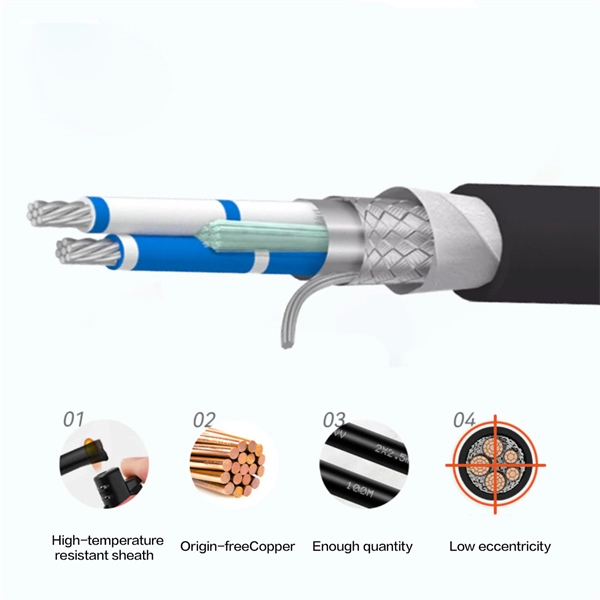
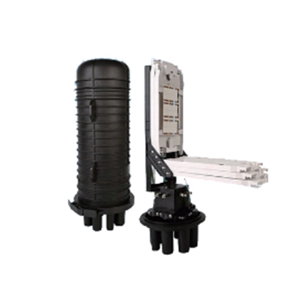
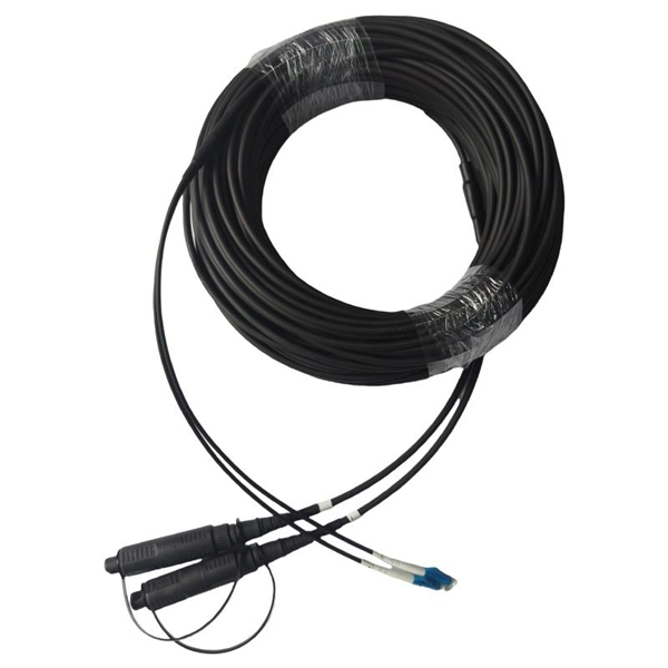
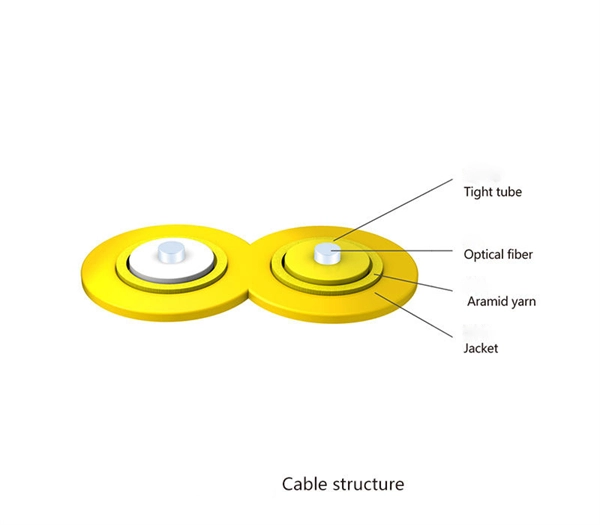
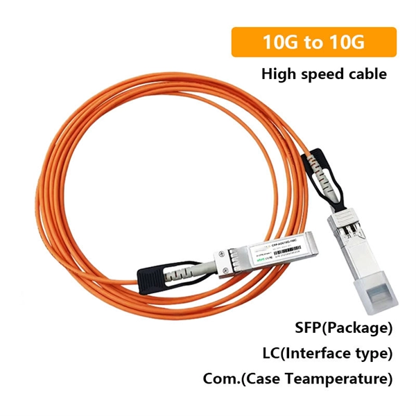
Main cost drivers include cable grade (indoor vs outdoor, armoured), distance, and labor for trenching, splicing, and termination. This guide presents ranges in USD and practical price estimates to help budget planning. Indoor OM3/OM4 vs outdoor armoured increases price. This guide outlines the major factors that influence fiber optic cable costs and provides practical tips for estimating pricing in bulk or project-based scenarios. Content 1 What's the Typical Price Range? 2 1. Fiber Count and Cable Construction 3 2. Fiber-optic cable materials typically cost $1 to $6 per linear foot, depending on fiber count and cable type. Commercial building installations with 100-200 network drops generally range from $15,000 to $30,000. Single-mode fiber costs less per foot than multimode fiber, but it requires more. Buyers typically pay for fiber optic cable by length, fiber type, and installation complexity. Fiber. The fiber optic cable protection tube market was valued at $1. 8 billion in 2023 and is expected to exceed $2. 1 mm diameter, containing 90 fire-resistant, flexible, and robust conduits.
[PDF]
There are many types of protective relays, and each one is designed for a specific type of protection. Common types include overcurrent relay, differential relay, distance relay, earth fault relay, and under/over voltage relay. Protective Relay Definition: A protective relay is an automatic device that senses abnormal conditions in electrical circuits and triggers actions to isolate faults. Types of Protective Relays: Protective relays are categorized by their mechanism (electromagnetic, static, mechanical) and function. This article covers various types of protective relays, such as overcurrent, directional, and differential relays, highlighting their operating characteristics and applications in electrical systems. Its main purpose is to safeguard electrical equipment like transformers, generators, and transmission lines from damage due to. Understanding the different types of protective relays and the applications of differential relays is crucial for anyone involved in electrical engineering or maintenance. The selection of relay depends on the type of equipment and fault. The rectangular devices are test connection blocks, used for testing and isolation of instrument transformer circuits. : 4 The first protective relays were electromagnetic.
[PDF]