In this video, we take you through the step-by-step installation of Optical Distribution Frames (ODF) and Optical Fiber Patch Panels—key components in setting up a robust fiber optic network. At Eman Communications, we specialize in delivering high-quality installations that ensure opt. more In. Fiber optic patch panels are mostly mounted in 19 inch relay racks, but they can also be mounted on freestanding rails, in cabinets and also on walls. The fiber optical patch panel is convenient for people to easily access the optical fiber cable in the panel. Keeping this page as a placeholder for now. Have any questions? Talk with us directly using LiveChat. An ODF is a centralized platform designed for terminating, cross-connecting, and managing optical fibers. It ensures fiber management is structured, minimizes signal loss, and provides accessibility for maintenance and future expansion. ODF Rack/Cabinet: Physical frame housing all terminations and. To connect fiber optic cables to a patch panel, users must follow a specific procedure that ensures proper connectivity and signal transmission. Here is a step-by-step guide on how to connect fiber optic cables to a patch panel. Step 1: Gather the Tools and Equipment The first step in connecting.
[PDF]
Fiber optic patch panels are enclosures that act as a distribution hub for fiber cable. A bulk (multi-strand) fiber cable enters the patch panel and then each fiber strand is separated into individual strands or pairs of strands. It acts as a hub for organizing splices and patch cords, streamlining fiber management and preserving signal integrity. These individual strands will then connect to electronic devices. A patch panel, including fiber patch panels and Ethernet patch panels, is a passive network device that centralizes, terminates, and organizes multiple copper or fiber cables. Serving as the interface between permanent cabling and active equipment, it provides clearly labeled ports that make. Structured cabling is a standardized system to help you organize and install the cables and hardware that connect your different devices to your network (including computers, servers, cameras, or any other smart gadgets). This article explores the structure, functionality, types, and benefits of fiber optic patch panels. What's the Fiber Optic Patch.
[PDF]
6Wresearch actively monitors the Nicaragua Optical Fiber Cables Market and publishes its comprehensive annual report, highlighting emerging trends, growth drivers, revenue analysis, and forecast outlook. Volza's Big Data technology scans over 2 billion export shipment records to identify new buyers, profitable markets, reliable suppliers, and promising products. Schedule a call with an Expert! According to Volza's Nicaragua Export data, Nicaragua exported 92 shipments of Fiber Optical Cable from. Costa Rica ECO-Residential Development & Business Guatemala: Terreno ideal para torres apartamentos (in spanish) Lindo terreno p/Torres Apartamentos a 12 minutos de Cayalá (in spanish) Panamá: Se vende estación de gasolina (in spanish) Take Back Your Life. Costa Rica $100,000 Income & Residency. Our customer's connections are integrated straight into a modern carrier MPLS network with access to all the territory and over +5,000 km of fiber optic in the Country. We provide coverage in Nicaragua and all over Latin America. Comfortable running services in L2 or L3, we pass through the leading. Reliable Supplier of Cabling and Connectivity Products. Cablexa Ltd is an ISO 14000:2004 & ISO 9001:2008 certified manufacturer specialized in R&D, production, sales and services of high performance cabling and connectivity products.
[PDF]
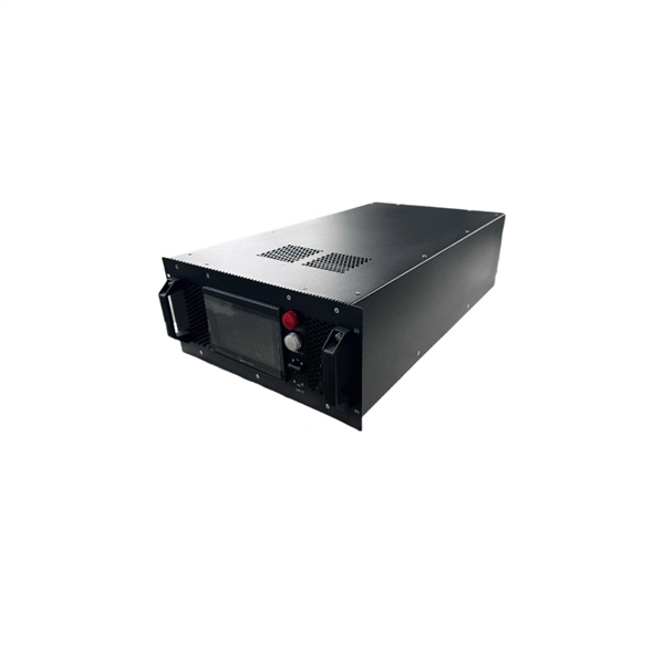
High Sensitivity, dynamic range, fast response (i., acquisition time), high reliability, low noise, compatible size with that of fiber, and low cost are some of the important requirements of a photodetector. An optical receiver is a device that converts light signals traveling through fiber optic cable back into electrical signals that electronic equipment can process. The. The SPIE Digital Library offers a comprehensive range of content on receivers, encompassing various aspects of their design, function, and application across multiple fields, particularly in optics and photonics. The library includes research articles, conference proceedings, and technical papers. decision circuit. With a return-to-zero signal (RZ) data format, a spectral component at the baud rate is present in the received signal, and the clock extraction can be accomplished with a narrow bandpass filter such as a phase-locked loop (PLL) or surface-acoustic- ave (SAW) filter. With non. Receiver sensitivity: This parameter specifies the required optical receive power to achieve a target receiver output performance, such as a target BER. A 3-dB increase in receiver sensitivity can be traded for a 3-dB reduction in optical transmit power, a 41% increase in free-space communication. The primary function of an optical receiver in an optical fiber communication link is to convert the received optical signal into an equivalent electrical signal and recover the data.
[PDF]
Find and discover Fiber Optic manufacturers and suppliers for all products in Laos, featuring details on their shipment activities, trade volumes, trading partners, and more. View all fiber optic buyers based on products in Laos. Subscribe to global trade data intelligence to discover new business. WWCC is upgrading the products operations through research, advanced technology and machinery, to serve the expanding needs of Laos's economy at competitive prices. The company is committed to offer high quality products to achieve customers' satisfaction. Our fiber optic cables are designed for use in laser surgery, endoscopy, photodynamic therapy, and diagnostic imaging, ensuring superior light transmission. How does 6W market outlook report help businesses in making decisions? 6W monitors the market across 60+ countries Globally, publishing an annual market outlook report that analyses trends, key drivers, Size, Volume, Revenue, opportunities, and market segments. Our insights help.
[PDF]
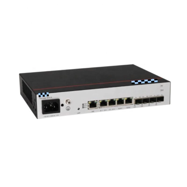
In this Cisco Tech Talk, learn how to view the optical module status on a Cisco switch using the Command Line Interface (CLI). This video demonstrates how to access the optical module status, check for any issues, and monitor the health of your network's optical components. Learn. When optical modules operate on a switch, it is usually necessary to read the module's internal information to understand its working status—such as connection status and real-time metrics like optical power and temperature. Additionally, identifying module information helps detect coding. This chapter describes how to configure the Optical Amplifier Module and Protection Switching Module (PSM). When you plan to replace a configured optical module with a different type of optical module, you must clear the configurations of the old module before you install the new module. By checking module health, compatibility, and digital diagnostics, you can quickly confirm correct installation, detect optical problems, and maintain accurate hardware. Small Form-factor Pluggable modules (SFP module) are the workhorses of modern network connectivity, enabling flexible fiber optic or copper links between switches, routers, firewalls, and servers. Whether you're upgrading bandwidth, replacing a faulty unit, or reconfiguring your topology, knowing.
[PDF]
This Technical Brochure describes the induction phenomena (inductive, capacitive and conductive) that can lead to presence of voltage and currents on disconnected cable systems. The optical fiber composite overhead ground wire (OPGW) has been widely used in power transmission lines. Methods of calculation to evaluate those values and touch voltages are detailed and analysed, associated with various. working on cables u al, photocopying, recording or otherwise, without the prior written or use by members of the Energy Networks Association to take account of the conditions which apply to them. Advice should. Literature review: An in-depth literature review covering the modelling and calculations of the conditions relating to faults caused by interactions between fibre optic cables and power cores in submarine cables. Examples of electrically conductive installations where induced voltage may occur could be: • Overhead lines or cables out of opera- tion •.
[PDF]
The system in this example contains the following elements: 1. 2 Pseudo-random Bit Stream (PRBS) block 2. 2 NRZ Pulse Generator (NRZ) 3. 1 CW Laser (CWL) 4. 3 1x2 Fork (FORK) 5. 2 Electrical Not Gate (N.
[PDF]
BARCELONA, Spain, March 6, 2025 /PRNewswire/ -- At the Mobile World Congress 2025 (MWC 2025), Huawei launched the StarryLink optical modules, designed to enhance network experiences with "3S" quality (Spanning, Stable, Secure). This announcement occurred during the data center session titled. Very little is written about Huawei's optical DWDM technology, but that doesn't mean the company hasn't made some big waves in the industry. We had the chance to sit down with the Huawei optical team, led by Gavin Gu, at MWC 2026 to learn about their latest coherent DWDM technology.
[PDF]
This paper aims to study the design, simulation, and optimization of low-loss Y-branch passive optical splitters up to 64 output ports for telecommunication applications. For a waveguide channel profile, the standard material silica-on-silicon is used. Two important technologies for optical layer monitoring are Optical Performance Monitoring (OPM) and Optical Power Detection (OPD). Although they aim to maintain network health, they differ significantly in scope, technique, and deployment. This article delves into these differences, equipping. Optical Performance Monitoring (OPM) is considered a necessity over an optical network to enable sensibility of traffic line status and attain outstanding Quality-of-Service (QoS). The Y-splitters are designed and simulated at. Passive optical networks (PONs) are the network architecture of choice for residential fiber deployments. A PON is designed specifically to be cost-effective for delivering high data-rates to large customer populations. signals and various components of OPM functionalities are indispensable robust network operation and plays a key role flexibility and improve overall. Optical performance monitoring (OPM) is used for managing high capacity dense wavelength-division multiplexing (DWDM) optical transmission and switching systems in Next Generation Networks (NGN). OPM involves assessing the quality of data channel by measuring its optical characteristics without.
[PDF]
The optical module is the foundation of optical communication that provides photoelectric conversion (see Figure 2). The photoelectric conversion efficiency of optical modules is crucial, and it directly affects the quality and performance of optical communications. From the technical level, HISILICON makes improvements. These two products are part of the LIGHTPASS ® Series active optical modules expected to be used for optical interconnection applications and IOWN* structures used for data centers and other uses. Demo kits for evaluating these products will be available from September 2023, and mass production is. Microwave photonics technology (MWP), which has been applied to various radar, Telcom, Electronic Warfare systems, is now facing more and more challenging development trend of miniaturization and modular array for increasing node counts and system complexity. In the context of data communication, it involves transforming data into light pulses for transmission through optical fibers and converting received light signals back into electrical. The optical module is the key device in all the links of this circulation process (see Figure 1). Two modules are used in pairs. The radio-frequency signal.
[PDF]
In this paper, a thermally tuned silicon-based three-channel reconfigurable multimode interference (MMI) optical power splitter with four optimized thermal isolations is proposed. Specific and flexible reconfig-urable functions (1, , and MMI splitters) can be achieved by. Abstract: We demonstrate integrated photonic circuits for quantum devices using sputtered polycrystalline aluminum nitride (AlN) on insulator. 56(1), 017106 (2017), doi: 10. The two most common types of splitters offered are polarizing beam splitters and polarization maintaining beam splitters. Their operating principles are as follows: Polarization Maintaining. optical transimission & integration needs of any system. MEISU specializes in precise custom fiber array sub-assemblies and PM fiber optical components and assemblies for different areas like integrated optics, sensoring, healthcare, spectroscopy, etc., 50/50 FBS, can be used as the frequency-mode Hadamard gate for frequency-encoded photonic qubits. Quantum cryptography is the key point of quantum communication. In classical cryptography classical bits are used but in quantum cryptography quantum bits (qubit) are used. Quantum communication sends the information through some channels such that, optical fibre, satellite etc.
[PDF]
Various optically switched architecture prototypes, based on the above optical switches, have been proposed to demonstrate the potential of optical data center networks. Optical data center networks are mainl.
[PDF]
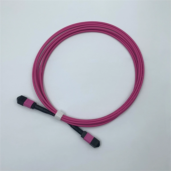
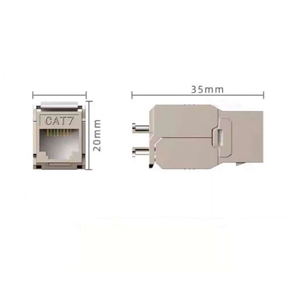
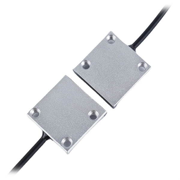
Insertion Loss (IL): Measures the amount of optical power lost at a connection point, typically expressed in decibels (dB). A lower IL value indicates better performance. designed for diverse fiber optic applications. But what exactly sets a fibe optic connector apart in terms of its merits? The primary purpose of a fiber optic connector is to terminate the ends of fiber optic cables, ensuring they can be int rconnected reliably with minimal optical loss. After. Optocouplers, also known as opto-isolators, are components that transfer electrical signals between two isolated circuits by using infrared light. As an isolator, an optocoupler can prevent high voltages from affecting the side of the circuit receiving the signal. Transferring signals over a light. Optical connectors are used to connect optical devices to other optical devices or systems. However, each connection introduces a certain amount of insertion and return loss that. When measuring the attenuation effects of the fiber connectors, insertion loss (IL) and return loss (RL) are two essential parameter measurements. While many factors influence these losses, the type of fiber optic connector used plays a crucial role. This article explores various connector types—such as SC, LC, FC, ST.
[PDF]
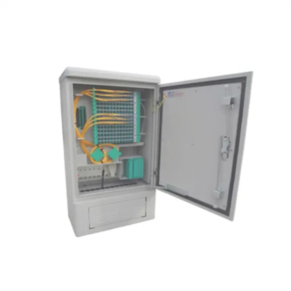
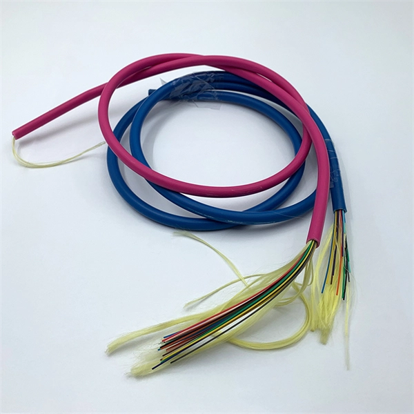
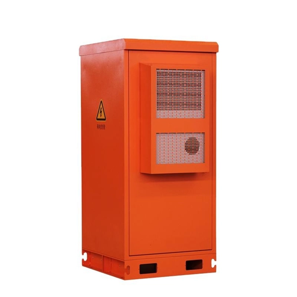
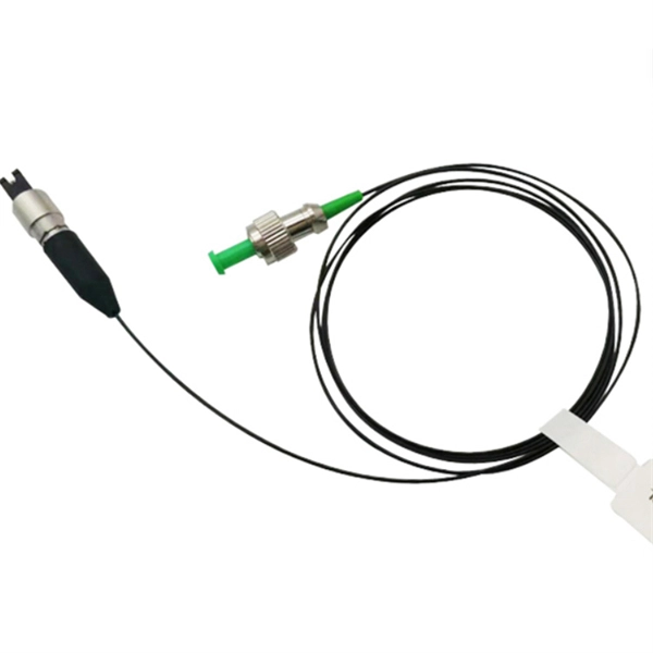
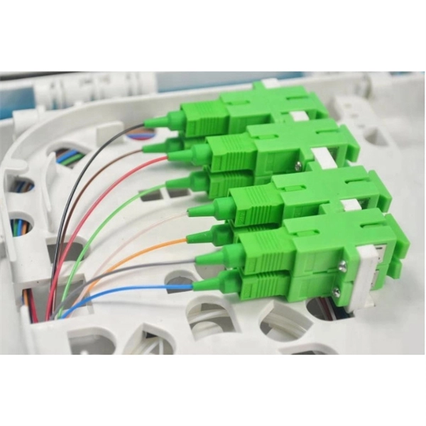
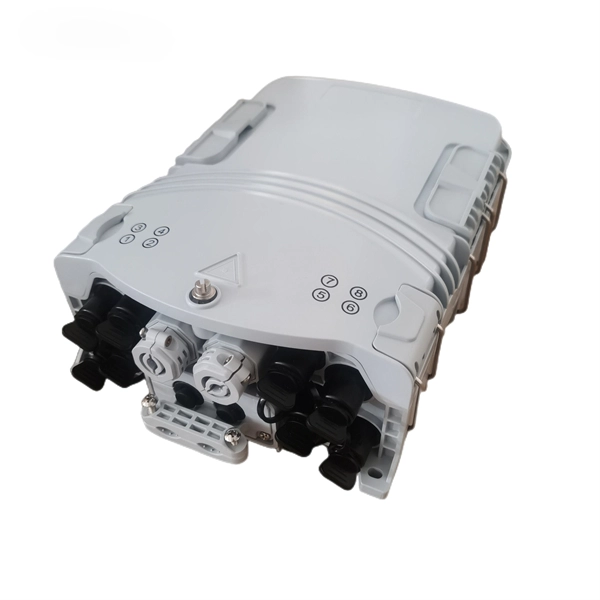
Through the adapter in the distribution box, the optical signal is led out by the optical jumper to realize the optical wiring function. An optical cable consists of three primary parts: the core, the cladding, and the protective sheath. The core is at the center of the optical cable and serves as the pathway for transmitting light signals. Surrounding the core is the cladding, which has a lower refractive index than the core. In the complex architecture of fiber optic networks, the Optical Distribution Frame (ODF) serves as the linchpin for organizing, protecting, and distributing optical signals. Whether in data centers, telecom central offices, or enterprise network rooms, ODFs enable efficient fiber management. The optical fiber distribution box is to protect the connection point where the optical cable is connected to the user end, so that the optical cable access point is stable, dustproof and waterproof. What is a fiber distribution box? 2. The. A fiber distribution box (FDB) functions as a central hub in fiber optic networks where the main cable is split into multiple individual fibers for distribution to end users. These boxes protect sensitive fiber connections from environmental factors while providing an organized framework for.
[PDF]