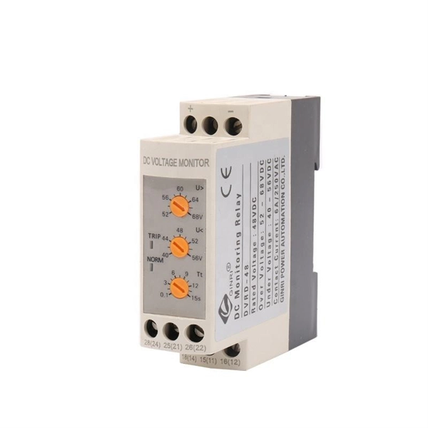
The SC pigtail is not properly plugged into the slot of the fiber media converters or has been disconnected. Check whether the fiber optic line is broken. This unit is designed to provide a safe and efficient means to transport and operate the Condux Fiber Optic Cable Puller (figure 1). The trailer offers the platform for a self-contained cable pulling system including a hydraulic power source, cable puller mounts, leveling and stabilizing hardware. Package contains: Fiber Optic Cable Puller, Foot Control and Hoses. Does not include a remote mounting stand or a base mount. Please order separately. Package contains: All items from package 1 plus electronic tension monitoring components including an Electronic Control Box. We have 1 Condux Fiber Optic Cable Puller Trailer manual available for free PDF download: User's Manual & Safety Manual Condux Fiber Optic Cable Puller Trailer Pdf User Manuals. View online or download Condux Fiber Optic Cable. An underground cable puller is a powerful piece of mechanical equipment designed to pull fiber optic, electrical, or communication cables through conduits or ducts.
[PDF]
Fibre Channel is a high-speed network technology used to connect server to data storage area network. It supports data backup and replication. Fibre Channel is needed, as it is very flexible and enables the. Fibre Channel (FC) is a high-speed data transfer protocol providing in-order, lossless delivery of raw block data. Fibre Channel networks form a. While the SCSI Application Layer (SAL) and the SCSI Transport Protocol Layer (STPL) are inherently part of the SCSI specification, the Interconnect Layer can be implemented by a variety of interconnect methods such as the SCSI Parallel Interface (SPI), Fibre Channel, InfiniBand or TCP/IP, to name. “The Fibre Channel Industry Association (FCIA) is a mutual benefit, non-profit, international organization of manufacturers, system integrators, developers, vendors, industry professionals, and end users. FC-2M. The intention of the Fibre Channel (FC) is to develop practical, inexpensive, yet expendable means of quickly transferring data between workstations, mainframes, supercomputers, desktop computers, storage devices, displays and other peripherials. Fibre Channel is the general name of an integrated. Fibre Channel Architecture This chapter includes the following main sections: The two most common peripheral protocols for device communication in the computer industry are networks and channels. Networks Channels Fibre channel attempts to combine the best of these two methods into an I/O interface.
[PDF]
Modern fiber-optic communication systems generally include optical transmitters that convert electrical signals into optical signals, optical fiber cables to carry the signal, optical amplifiers, and optical receivers to convert the signal back into an electrical signal. The information transmitted is typically digital information generated by computers or telephone systems. Transmitters The most commo. OverviewFiber-optic communication is a form of for from one place to another by sending pulses of or through an. The light is a form of. First developed in the 1970s, fiber-optics have revolutionized the industry and have played a major role in the advent of the. Because of its advantages over electrical transmission, optical fiber. is used by telecommunications companies to transmit telephone signals, Internet communication and cable television signals. It is also used in other industries, including medical, defense, governmen.
[PDF]
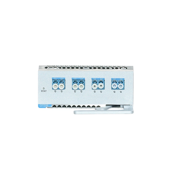
This step-by-step guide aims to provide a comprehensive understanding of the techniques and considerations involved in successfully connecting optical fibers, offering invaluable insights for professionals and enthusiasts in the field. In high-speed data networks, the seamless integration of fiber optic cables with SFP (Small Form-Factor Pluggable) modules is critical for reliable signal transmission. SFP transceivers bridge electrical and optical signals, making them indispensable in data centers, telecom networks, and. Proper connection of fiber optic cables is essential to harness these benefits fully, as even minor errors can lead to significant performance issues like signal loss. This article will guide you through the necessary tools, materials, and methods on how to connect fiber optic cables effectively. This section describes how to install optical transceivers on the SFP or SFP+ ports and connect them to the ports of the peer device using optical fibers according to the network plan. The USG supports both 1 Gbit/s, 10 Gbit/s, and 40 Gbit/s optical modules. The optical modules at both ends are. There are many types of fiber optic connectors, including SC, LC, FC, ST, D4, MU, MT/MPO, etc. These connectors can be divided into single-mode and multi-mode fiber optic connectors according to their structure and purpose. In this tutorial.
[PDF]
Typical rates range from $75 to $180 per hour per technician, with on-site time often dominating the total. Hidden costs include traffic control, trench restoration, and post-repair verification testing. Prices for fiber optic repair vary by issue type, location, and required work. This guide lays out cost expectations, with clear low–average–high estimates and regional nuances. Includes fusion/splice, testing, and basic materials. This guide provides practical cost ranges in USD with. In the United States, fiber optic repair typically costs a few hundred to several thousand dollars, depending on the scope of the fault, distance of the fiber run, and required components. The cost to fix a fiber line often hinges on the fault type, distance, and response time, with price ranges reflecting differing crews and materials.
[PDF]
At present, key breakthroughs in optical fiber communication technology include high-order modulation formats, polarization multiplexing, wavelength division multiplexing, etc. Optical fiber communication can be widely applied in the fields of the internet and telephone networks . With the rapid development of cloud computing, big data, the Internet of Things, and other new technologies, we have entered an era of digitalization and informatization. The number of internet users has been steadily increasing, which has accelerated the exponential expansion of data services. A. Then the different technologies in optical fiber communication along with their features are discussed briefly.
[PDF]
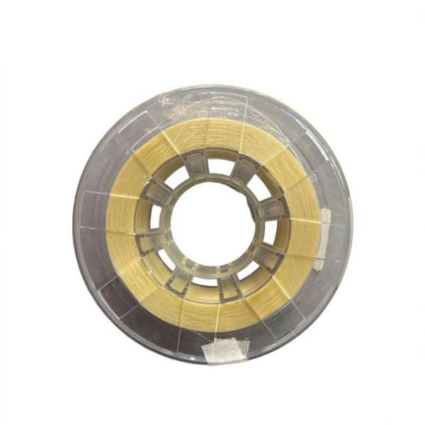
The V-groove substrate is the heart of the Fiber Array, providing precise alignment for the optical fibers. This substrate, typically made from silicon, glass, or ceramic, features a series of V-shaped grooves etched with sub-micron accuracy. Fiber Array (FA for short) is an array formed by installing a bundle of optical fibers or a fiber ribbon on the substrate at specified intervals by using a V-Groove (V-Groove) substrate. Fiber optic arrays in optical communications mainly include a substrate, a platen, and an optical fiber. Whether integrated into planar lightwave circuits (PLCs), optical switches, or high-speed transceivers, FAs play a vital role in ensuring. What is a Fiber Array (FA)? A Fiber Array, commonly abbreviated as FA, is a critical interface component in Silicon Photonics (SiPh) packaging, Photonic Integrated Circuits (PIC), and Co-Packaged Optics (CPO) architectures. It is responsible for efficiently coupling "external optical fibers" with. Fiber Arrays (FAs), as high-precision, high-performance optical components, have become indispensable core elements in fields such as optical communications, photonic integration, and laser processing. Typically, such an array is formed only for the very end of the fibre bundle, rather than over the entire length of the.
[PDF]
This paper describes a disruptive continuous monitoring system to detect Corrosion Under Insulation (CUI) risks for every meter of pipeline over large distances. Distributed Fiber Optic Sensing (DFOS) has emerged as a viable non-destructive ATEX-proof solution to detect CUI. ors by depositing metal coatings to the surface of the sensors. Three types of fiber optic sensors were investigated as candidates for corrosion detection: the extrinsic Fabry-Perot interferometer (EFPI), the absolute extrinsic Fabry-Perot interferomete (AEFPI), and the long period grating (LPG). This paper presents a distributed monitoring approach for detection, visualization, quantification, and warning for pipe corrosion using a single-mode telecommunication-grade fiber optic cable as a distributed sensor. The distributed sensor can be deployed on the surface of a pipe to measure. Fiber optic AE sensor was tested due to its anti-explosiveness, fitting to petrochemical plants. Experiment was successful, and one sensor could detect approx. 4,000mm-away corrosion. Our study attempts to detect. Experimental Investigation for Monitoring Corrosion Using Plastic Optical Fiber Sensors Liang Hou 1,*, Shinichi Akutagawa 1, Yuki Tomoshige 2and Takashi Kimura 2 1Department of Civil Engineering, Kobe University, 1 -1, Rokkodaicho, Nadaku, Kobe 6578501, Japan; cadax@kobe-u. jp 2Engineering.
[PDF]
Interactive anomalies of pipelines represent important contributors to pipeline incidents, but monitoring interactive anomalies is challenging. This paper presents an approach to monitor interactive bend.
[PDF]
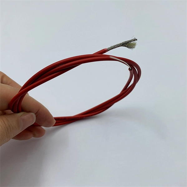
The os3150 and os3155 are rugged, spot-weldable optical strain gage based on fiber Bragg grating (FBG) technology, with optional integrated temperature compensation. The os3100 Optical Strain Gage is designed to make fiber handling easy and sensor installation fast and repeatable. Its stainless steel carrier holds the FBG in tension, using no epoxy. SCAIME has developed a complete range of fibre-optic strain gauges for monitoring complex structures. Since there are no. What are Optical Strain Sensors? Optical strain sensors (or strain gauges) are sensors for compressive and/or tensile mechanical strain (deformation) which are based on optical technology — in most cases, on fiber optics. They can be based on different operation principles as explained in the. Fiber Bragg grating strain gages can be delivered pre-laminated for measuring strain on stiff surfaces. They are suitable for being fixed easily onto the measurement object, like concrete beams, or rocks. These sensors possess great sensitivity and reliability, which explains their growing popularity across various engineering and monitoring applications. The fiber optic strain gauge is directly attached onto the.
[PDF]
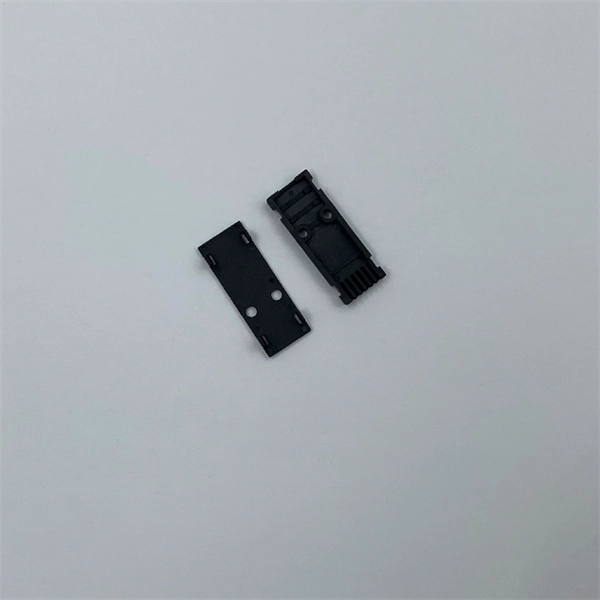
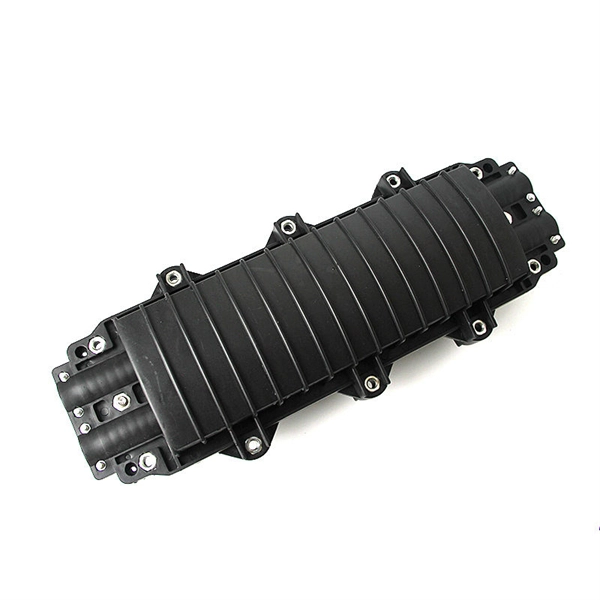
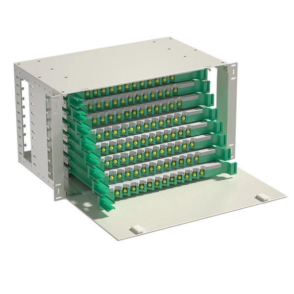
The core principle of fiber optic splicing is to achieve low-loss, high-strength junctions between fiber ends. This involves three key steps: preparation, alignment, and bonding. Let's break it down technically:. At the core of this system's precision and reliability are Fiber Optic Splice Boxes—the unsung heroes that house and protect the delicate junctions where fiber cables are joined. The integrity of these enclosures is paramount to network performance. This guide optimizes the original text by delving. A splice box (also known as splice distributor) is a housing in which fiber optic cables begin or end. Key Functions Typical Applications ZION FTB Highlights In essence: The Fiber Terminal Box is an end-user termination device for small-scale distribution. ■ What Is a Fiber. Fiber optic cables are the lifeline of modern telecommunications, delivering high-speed data with minimal loss. However, installing and maintaining these networks requires seamless connections between fiber segments—a process known as fiber optic splicing. Understanding how it works is essential for anyone interested in telecommunications or network infrastructure. Essential for mending faults or scaling networks, splicing underpins the backbone of contemporary communications. In this comprehensive guide.
[PDF]
We terminate fiber optic cable two ways - with connectors that can mate two fibers to create a temporary joint and/or connect the fiber to a piece of network gear or with splices which create a permanent joint between the two fibers. Proper connection of fiber optic cables is essential to harness these benefits fully, as even minor errors can lead to significant performance issues like signal loss. These terminations must be of the right style, installed in a. Running fiber internally involves extending this high-speed link from the service entry point to a centralized location, such as a dedicated media closet or network rack. This DIY effort is undertaken to maximize performance, improve aesthetics, or relocate the Optical Network Terminal (ONT) to a. In this video, we'll guide you through preparing and terminating fiber optic cables using SimplyFiber products, known for their high quality, ease of use, and reliability. more Audio tracks for some languages were automatically generated. Two types of splices are used in fiber optic cabling one is Mechanical the other is Fusion. Whether you're installing a new network, expanding an existing one, or. But here's the thing: how you connect fiber optic cable really matters. A shaky connection means weaker signals, dropped streaming, or slow uploads. Get the hookup right, and you'll enjoy streaming, gaming, and video calls without interruptions.
[PDF]
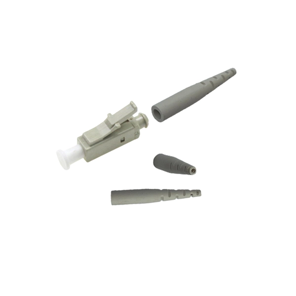
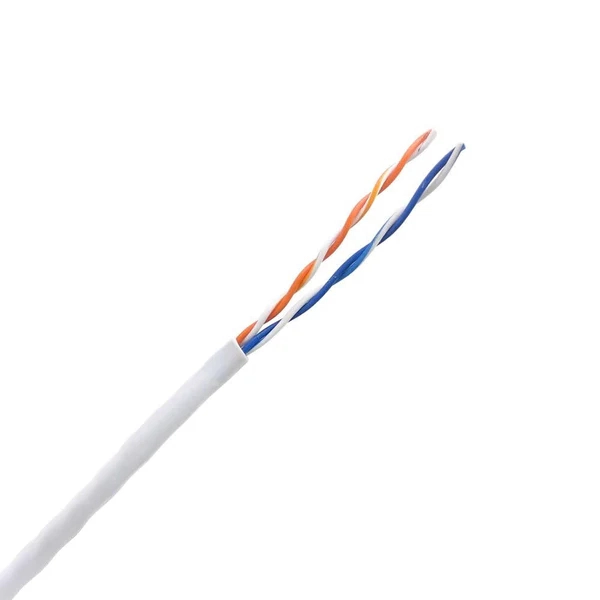
A variety of optical fiber connectors are available, but SC and LC connectors are the most common types of connectors on the market. Typical connectors are rated for 500–1,000 mating cycles. The main differences among types of connectors are dimensions and. An optical fiber connector is a device used to link optical fibers, facilitating the efficient transmission of light signals. They come in various types like SC, LC, ST, and MTP, each designed for specific. Fiber connector types LC, SC, FC, ST, MTP, and MPO are widely used in past and present. What are the differences between them? Who is the most popular one? Find the answer in the article. What is a Fiber Connector? The optical fiber connector is a kind of detachable passive optical component used. Fiber optic cable assembly quality hinges on selecting the right connector type—most commonly LC, SC, or ST—to match device ports and installation environment. When selecting the appropriate optical module for a network application, one crucial factor to consider is the type of fiber connector it employs. Fiber optic connectors are used to the mechanical and optical means for cross connecting fibers. There have been many types of connectors developed for fiber cable. With the demands of different application scenarios.
[PDF]
This video makes connecting your fiber optic cable to your router a breeze! We'll guide you through the entire process step-by-step, ensuring a smooth and hassle-free experience. Our Experts are helping user's, who are facing issues with their tech gadgets like. In this guide, we'll walk you through how to connect a fiber optic cable to a router safely and efficiently. Why Use Fiber Optic Internet? Before diving into the setup, let's quickly recap why fiber optics are worth the effort: Lightning-fast speeds (up to 1 Gbps or higher). This comprehensive guide combines industry standards with field-tested practices to ensure you achieve a rock-solid. Setting up a fiber internet connection requires understanding key hardware components and following a specific connection sequence to establish your home network. This guide details the necessary physical and digital steps to connect your fiber line and activate your internet service. If you. Connecting a fiber optic cable to a router might seem daunting at first, but with the right tools and a bit of patience, it's a straightforward process. Here's a step-by-step guide to help you through it. Check compatibility: Before you begin, make sure your router supports fiber optic connection. Not all routers can connect directly to a fiber cable, so it is important to verify this information before continuing.
[PDF]
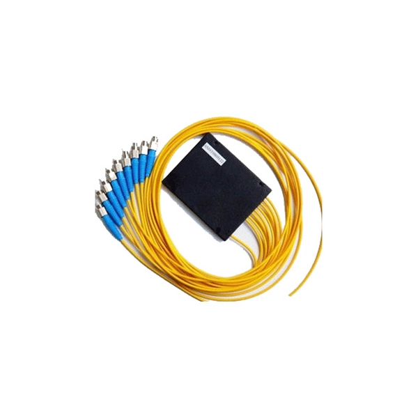
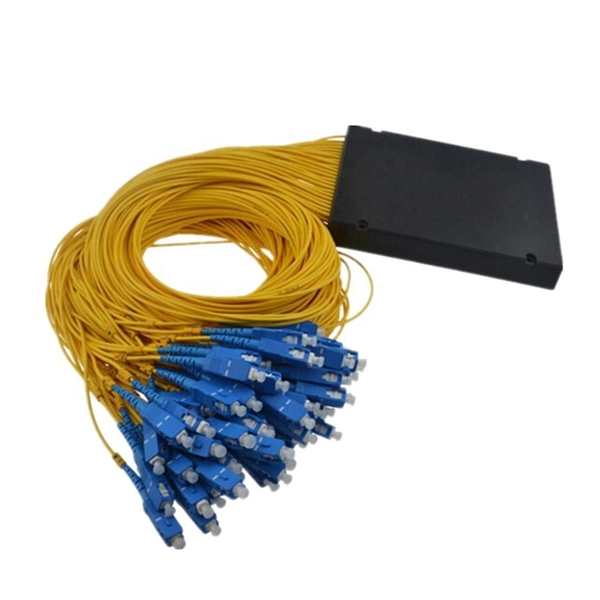
In this video, I walk you through my personal method of prepping and installing a 1:16 fiber optic splitter inside a sealed, weatherproof distribution box getting it ready for field deployment at a site. This is the way I've found to be clean, efficient, and reliable based on my experience in the. Optical splitters offer a cost-effective and dependable solution across various fiber optic applications. Also known as optical splitters, fiber splitters, or beam splitters, these devices are integrated waveguides ensuring wide bandwidth and minimal loss in high-frequency applications. They. How to install the splitter distribution box is the important information we need to know. This article includes the following: 1. Install the fixture 2. Ground the installation system 1. Have any questions? Talk with us directly using LiveChat. Fiber optic cable s transmit data using light signals, allowing for faster and more efficient data transfer compared to traditional copper cables. In the world of fiber optics, a crucial component for distributing signals is the fiber optic splitter box.
[PDF]