There are currently three methods of looking inside a fiber optic connector: (1) Non-destructive X-ray (2) Lossless sonar (3) Destructive cross section These methods help engineers determine the causes and effects of fiber optic connector failures and monitor the connector assembly. There are currently three methods of looking inside a fiber optic connector: (1) Non-destructive X-ray (2) Lossless sonar (3) Destructive cross section These methods help engineers determine the causes and effects of fiber optic connector failures and monitor the connector assembly. Fiber Optic Center offers a unique cross-sectioning service to identify and isolate problems related to fiber optic terminations that would otherwise be invisible. All. There are two major uses for visual inspection of fiber optic connectors. Video microscopes should have ability to record images and some may have ability to analyze connector condition to standards. Look for dirt, contamination, scratches or any other problem. Since connectors are susceptible to damage that is not immediately obvious to the naked eye—the inspection phase is vital. When proceeding with the inspection of connectors, there are two main components to inspect: the connector itself and the ferrule. With the press of a single button, FOCIS Flex auto-focuses, captures and centers the end-face image, applies Pass/Fail rules, displays image and Pass/Fail results, saves results internally and/or wirelessly transfers data to a.
[PDF]
EIA/TIA 568 B allows any fiber optic connector as long as it has a FOCIS (Fiber Optic Connector Intermateability Standard) document behind it. Fiber optic cold connection, also known as mechanical splicing, is a widely used method of connecting optical fibers in a network. Unlike fusion splicing, which uses heat to join two optical fibers together, cold connection uses mechanical means to create a stable and low-loss connection. Unlike fiber splicing, which is permanent, connectors allow for easy connection and disconnection of cables, making them ideal for maintenance and flexibility in. Fiber optic joints or terminations are made two ways: 1) splices which create a permanent joint between the two fibers or 2) connectors that mate two fibers to create a temporary joint and/or connect the fiber to a piece of network gear. These terminations must be of the right style, installed in a. Fiber termination refers to the process of preparing the end of a fiber optic cable to connect to another fiber, a device, or a network. Proper termination is essential for ensuring optimal performance, reducing signal loss, and maintaining the durability of the connection. Since the introduction of fiber optic technology decades ago, a variety of connector types have been.
[PDF]
Explore a vast selection of robust and reliable connectors at Norwegian Electronic Supply AS. Designed for subsea and marine applications, our connectors ensure optimal performance. High-quality fiber cables, connectors, and assemblies for enterprise and infrastructure networks. Fiber connectivity engineered for shock, vibration, temperature extremes, and demanding field. T&G is a leading manufacturer and distributor of connectivity solutions including cables, harnesses, connectors, fiber optic boards, tools, and accessories. of our DNA and is incuded in everything we do. T&G is certified to EN9100 (AS9100), ISO9001 and ISO14001. our customers' needs. Hos oss finner du alt du trenger til ditt fibernett! Fiberworks is a specialized manufacturer in the fiber optic market, offering a variety of products and services. Several functions. One cable | Smart cable solutions. Our selection also includes Huber+Suhner's portfolio of their self-developed connectors for. The M Series connectors meet the highest standards of safety for deep immersion. It is currently used in many applications: from oil and gas industry service to renewable energy generation system and military submarines. The M Series feature a large range of shell styles, layouts or insulator.
[PDF]
Mouser offers inventory, pricing, & datasheets for LC Adapter Duplex Fiber Optic Connectors. The LC duplex adapter blockout device shall work with LC duplex adapters that are TIA/EIA-604 FOCIS-10 compatible. Each device shall block two LC connector spaces keeping them secure and reducing the risk of damage to the LC adapter. Anixter is your source for Fiber Optic Adapters products. Check each product page for other buying options. Fibershack - LC Coupler Tin - 20 Pack - Single Mode LC Fiber Couplers Set. LCUPC Fiber Adapters are Pre-Cleaned & Extend LCUPC Optical Cables. Connects SM Simplex or Duplex Cables Need help?. LC Adapters are essential optical connectors used to join LC-terminated fiber optic cables with minimal signal loss. Designed for high-density network environments, these adapters ensure precise alignment of fiber cores, maintaining high-quality transmission. Fiber optic's advantages over copper cabling are well known immunity to EMI and RFI, low attenuation over long distances, high bandwidth capacity, smaller size and lower weight. Fiber optic cable is also difficult to tap and intercept. Optimize your high-density network with our SC duplex fiber adapter module. This module supports simultaneous bidirectional data transmission, making it perfect for LAN, SAN, and public networks. This module supports. Fiber Optic Connectors Mini-Com Duplex Keyed/Non-Keyed LC Adapter Module Keyed A-Blk Adapter half on User side and No key on Service Side.
[PDF]
Passive media components such as cables, cable splices, and connectors cause attenuation. Although attenuation is significantly lower for optical fiber than for other media, it still occurs in both multimode and single-mode transmissions. Two fundamental mechanisms cause attenuation inside the fiber itself: absorption and scattering. These are intrinsic to the glass, meaning they exist even in a perfectly manufactured, perfectly installed fiber. Scattering is the bigger factor at the wavelengths most networks use. The silica glass. Optical attenuation is the gradual loss of flux (light intensity) as an optical signal travels through a fiber. Measured in decibels (dB), it's the logarithmic ratio of the output power to the input power. Every network has a "loss budget". F iber optic networks rely on the efficient transmission of light signals to deliver high-speed data over long distances. However, various factors can cause signal degradation, leading to performance issues and reduced network reliability. You may see slower speeds and less steady connections when signal loss goes up. Things like impurities in the fiber core and reflections at the core-cladding edge cause this drop. This can be due to a variety of factors: scattering and absorption, intrinsic. Signal attenuation in fiber optics is a key concept in telecommunications. It affects how far a signal can travel without losing.
[PDF]
A variety of optical fiber connectors are available, but SC and LC connectors are the most common types of connectors on the market. Typical connectors are rated for 500–1,000 mating cycles. The main differences among types of connectors are dimensions and. An optical fiber connector is a device used to link optical fibers, facilitating the efficient transmission of light signals. They come in various types like SC, LC, ST, and MTP, each designed for specific. Fiber connector types LC, SC, FC, ST, MTP, and MPO are widely used in past and present. What are the differences between them? Who is the most popular one? Find the answer in the article. What is a Fiber Connector? The optical fiber connector is a kind of detachable passive optical component used. Fiber optic cable assembly quality hinges on selecting the right connector type—most commonly LC, SC, or ST—to match device ports and installation environment. When selecting the appropriate optical module for a network application, one crucial factor to consider is the type of fiber connector it employs. Fiber optic connectors are used to the mechanical and optical means for cross connecting fibers. There have been many types of connectors developed for fiber cable. With the demands of different application scenarios.
[PDF]
Fiber optic connectors can be categorized according to different standards such as utilization, fiber count, fiber mode, and transmission method. They are also divided into single-mode and multimode types based on their distinct characteristics. The fiber connector types, sometimes referred to as terminations, link fiber optic cables together through terminals, switches, adapters, and patch panels, by bridging the gap between their internal glass fibers that transmit the data down the length of the cable. And based on the connector construction, LC connector also can be divided into LC duplex and simplex connector. a single mode fiber (SMF). And it has a “square shaped” connector body, which is the source of name “square connector”. Due. Fiber optic connectors, according to the different transmission media, can be divided into common silicon-based fiber single-mode and multimode connectors, and other such as plastic as the transmission medium of fiber optic connectors; according to the connector, structure form can be divided into:. A fiber optic connector is a mechanical device used to align and join optical fibers, enabling light to pass through with minimal loss. Simplex vs duplex fiber connectors, single mode vs multimode fiber connectors, what's the difference? This article will explain the above to you.
[PDF]
This interactive submarine cable map shows global undersea and underwater fiber optic cables connecting continents and countries worldwide. Explore cable routes, landing stations, system status and infrastructure updates. This visualization shows the growth of the undersea cable network, global internet peering capacity, and the distribution of IP addresses via BGP announcements over time. Use the controls at the top to play the animation or step through year by year. For more details and insights, please read this. Deep Sea Laying System will dominate with a 59. 0% market share, while digital communication infrastructure will lead the application segment with a 64. The offshore fibre optic cable lay market is valued at USD 3. 0 billion in 2025 and is forecasted to reach USD 6. 5 billion by 2035. Fibre-optic Link Around the Globe (FLAG) is a 28,000-kilometre-long (17,398 mi; 15,119 nmi) fibre optic mostly- submarine communications cable that connects the United Kingdom, Japan, India, and many places in between. As digital economies expand and geopolitical tensions shape technological dependencies, undersea cables emerge not. The global Offshore Fibre Optic Cable Lay market size is expected to reach $ 4745 million by 2031, rising at a market growth of 7. 8% CAGR during the forecast period (2025-2031). Offshore Fibre Optic Cable Lay refers to the process of installing fibre optic cables on or beneath the seabed to enable.
[PDF]
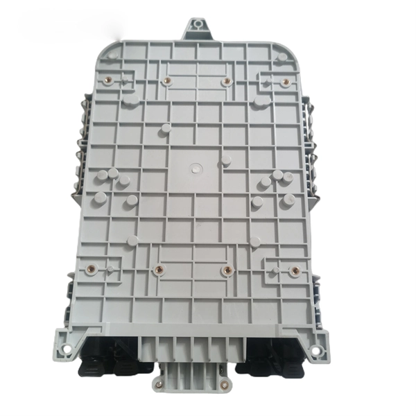
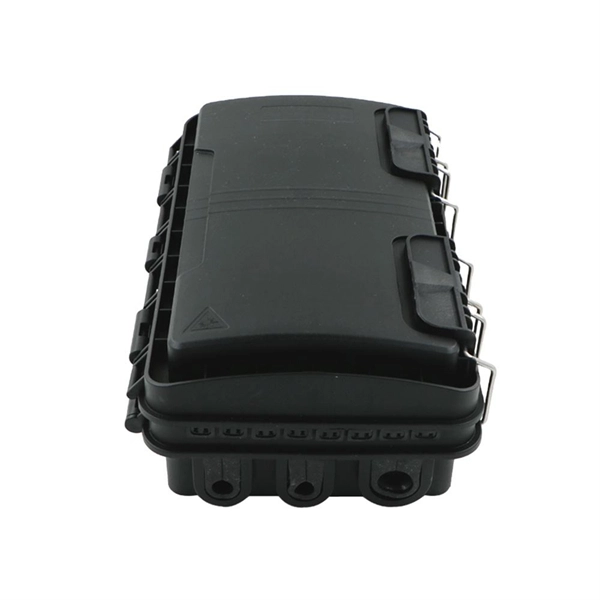
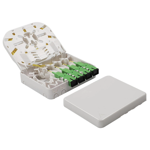
This video provides a step-by-step guide on how to efficiently install optical splitter into a fiber terminal box, demonstrating a professional and reliable deployment for optical distribution network solution ( https://www. com/c/optical-distribu. We'll also share tips to minimize signal loss and ensure optimal performance. What Is a Splitter and Why Cascade Them? A splitter divides a single input signal into. When employing the first-level splitting method in a residential network, optical splitters offer flexibility for indoor or outdoor installation. Indoor options encompass locations like the community's central computer room, building's weak current well, or floor wiring box. Optical cables can be. If you have fiber optic cable inside your home, it is possible to install a cable into the home input then split the signal so you can connect the signal to two different television hookups. Insert one end of the fiber optic cable into the "In" port accessible through your wall. The splitter box contains a splitter, which is a passive optical device that divides the incoming light signal. How to install and use fiber optic cable splitter? In fact, the installation of the fiber optic cable splitter is very simple, because it is already a cable terminal product, mainly to see whether it is with a fiber connectors or not, and the packaging type. For example, plc splitter without.
[PDF]
The projected fiber optic splicer job growth rate is 6% from 2018-2028. About 13,600 new jobs for fiber optic splicers are projected over the next decade. — (September 22, 2025)—Today the Fiber Broadband Association (FBA) and NCTI, a leading broadband and network training solutions provider, unveiled the results of a joint workforce preparedness survey. The findings have been published in a paper titled, “Employer Workforce. The fiber optic splicer market is experiencing robust growth, driven by the expanding global telecommunications infrastructure and the increasing demand for high-speed internet connectivity. The market's Compound Annual Growth Rate (CAGR) is estimated at 7% for the period 2025-2033, indicating a. Government broadband funding is flowing, but the technicians and engineers to build fiber networks don't exist in sufficient numbers. Telecoms are getting creative with recruiting. The Bipartisan Infrastructure Law allocated $42. 5 billion for broadband deployment through the BEAD program. State. Data-driven look at fiber optic and broadband technician careers, including the 178,000-worker shortage driven by $42. 5B in federal broadband investment, salary data, certification paths, and why this may be the best-timed trade career in a generation. Fiber network deployments in the US, while hitting a bit of a slowdown, are proceeding apace and will ramp up significantly as grants start.
[PDF]
Fiber optics enable high-speed, interference-free communication for industrial systems. Choose single-mode for long-range, multimode for local/plant applications. Fiber is crucial for IT/OT integration, safety systems, and SCADA communication. flammable media, and good electromagnetic compatibility (EMC). As the world's largest fiber optic components and subsystem manufacturer, Coherent is best positioned to provide the Fast Ethernet and Gig such as Fast Ethernet (125 Mb/s) and Gigabit Ethernet (1 Gb/s). Distances for these links may. Fiber optics refers to the transmission of data as light pulses through strands of glass or plastic fibers. Each fiber strand is thinner than a human hair and capable of transmitting data over long distances at the speed of light. Core: Carries the light signal (glass/plastic). Cladding: Reflects. With the global fiber optics market projected to reach USD 9. 73 Billion by 2027 (Source-GlobeNewsWire), it is clear that the demand for fiber optic cables across industries is only going to increase. Today, we are going to discuss the industrial use cases of optical fiber in different industries. • Real-time Control: Optical fibers.
[PDF]
This complete guide explores everything you need to know about ODFs — from their structure, types, and key components, to installation best practices and modern design trends. Whether you're building a central office, data center, or FTTx distribution network, understanding the right ODF. In modern data centers and enterprise networks, Optical Distribution Frames (ODF) serve as the backbone for organizing, terminating, and managing fiber optic connections. This article explores the types, components, applications, installation, and maintenance best practices, providing a. An Optical Distribution Frame (ODF) is the central hub for fiber splicing, termination, patching, and cable protection in modern optical networks. As data centers, enterprises, telecom operators, and smart-building infrastructures deploy increasingly dense fiber links, ODFs provide the structured. Achieve successful cable management, handle high amounts of fiber cable and add density to fiber frames with the new DCX Optical Distribution Frame (ODF) System which features innovations like flippable cassettes, modular frame design and multiple configuration options. The ODF System Components. Optical distribution frames (ODFs) are an all-important network element at the heart of a fiber network. They provide efficient fiber optic management, connectivity, and protection.
[PDF]
This paper provides a systematic introduction to the principle of FP cavity fiber optic sensors based on thin film technology and reviews the applications and development trends of this sensor in various measurement fields. Currently, there is a growing need for precise measurements in both. This is the power of fiber optic sensing, a technology that transforms ordinary optical fibers into the digital world's sensory network. In 2023, researchers turned submarine cables into earthquake warning systems and gave electric vehicles “optical nerves” to prevent battery failures. It aims to provide a comprehensive collection of cutting-edge research that pushes the boundaries of fiber optic sensor technologies, integrating them with emerging trends and. Optical fiber (OF) sensors are critical optical devices with excellent sensing capabilities and the capacity to operate in remote and hostile environments. However, integrating functional materials and micro/nanostructures into the optical fiber systems for specific sensing applications has. The Fiber Optic Sensing Association (FOSA) is dedicated to accelerating the use of distributed and quasi-distributed optical fiber sensing technologies. Fiber optic sensing works by measuring changes in the “backscattering” of light occurring in an optical fiber when the fiber encounters vibration.
[PDF]
Fiber optic bundles consist of multiple optical fibers grouped together to transmit light signals simultaneously. These bundles are integral to various applications, including imaging systems, illumination, spectroscopy, sensors, and high-speed data transmission across diverse. A fiber optic bundle, (also known as a light guide or light pipe), is a multiplicity of single optical fiber strands. When this multiplicity of fibers is randomly gathered, it is usually collected in a jacket (buffer, sheathing, housing) and held together at each end with epoxy to form an output or. What is a Fiber Bundle? For some applications, some number of optical fibers is bundled together, forming a fiber bundle or fiber-optic bundle. In most cases, one uses multimode large-core silica fibers or plastic fibers. As technology advances and the demand for high-speed internet increases, understanding the fundamentals of fibre cable bundling becomes. Ribbon fiber optic cable is a type of optical fiber cable that consists of multiple individual fibers arranged in parallel within a flat ribbon-like structure. Instead of having individual round cables, ribbon cables have several fibers laid out side by side, typically in a flat and compact. A fiber optic bundle is designed to transmit light or image in the visible region of the spectrum. This article is going to introduce fiber optic bundles, and it is configuration examples, benefits, and applications.
[PDF]
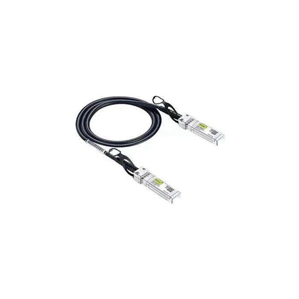
Most modern fiber-enabled network switches require an SFP transceiver module featuring a duplex (two strand) multimode OM3 or duplex single mode OS2 connection with LC connectors. Direct attach cables with pre-terminated SFP connections may also be used. Download the Application. CONFIGURING THE SWITCH IN DESIGO CC/CERBERUS DMS. CYBERSECURITY DISCLAIMER. 44. This tutorial will explain the steps required to configure fiber optics on a Cisco switch and ensure proper connectivity in your network. This chapter includes the following sections: •Information About Fibre Channel Interfaces, page 1-1 •Configuring Fibre Channel Interfaces, page 1-8 •Configuring Global Attributes for. : 192. 0 De livery of solutions fulfilling the Customers' multitude o. This document is intended to serve as a guide for architecting and deploying fiber optic networks in a customer environment. This installation planning guide describes some basic fundamentals of fiber optic technology, considerations for deployment, and basic testing and troubleshooting procedures. Fiber optic cabling is increasingly used to connect network switches and other datacom equipment, especially in long-distance and mission-critical applications. Fiber provides: Increased internet signal bandwidth.
[PDF]