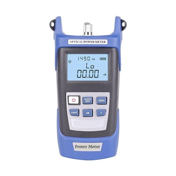
Passive media components such as cables, cable splices, and connectors cause attenuation. Although attenuation is significantly lower for optical fiber than for other media, it still occurs in both multimode and single-mode transmissions. Two fundamental mechanisms cause attenuation inside the fiber itself: absorption and scattering. These are intrinsic to the glass, meaning they exist even in a perfectly manufactured, perfectly installed fiber. Scattering is the bigger factor at the wavelengths most networks use. The silica glass. Optical attenuation is the gradual loss of flux (light intensity) as an optical signal travels through a fiber. Measured in decibels (dB), it's the logarithmic ratio of the output power to the input power. Every network has a "loss budget". F iber optic networks rely on the efficient transmission of light signals to deliver high-speed data over long distances. However, various factors can cause signal degradation, leading to performance issues and reduced network reliability. You may see slower speeds and less steady connections when signal loss goes up. Things like impurities in the fiber core and reflections at the core-cladding edge cause this drop. This can be due to a variety of factors: scattering and absorption, intrinsic. Signal attenuation in fiber optics is a key concept in telecommunications. It affects how far a signal can travel without losing.
[PDF]
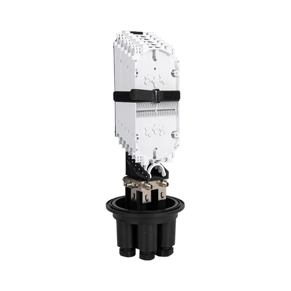
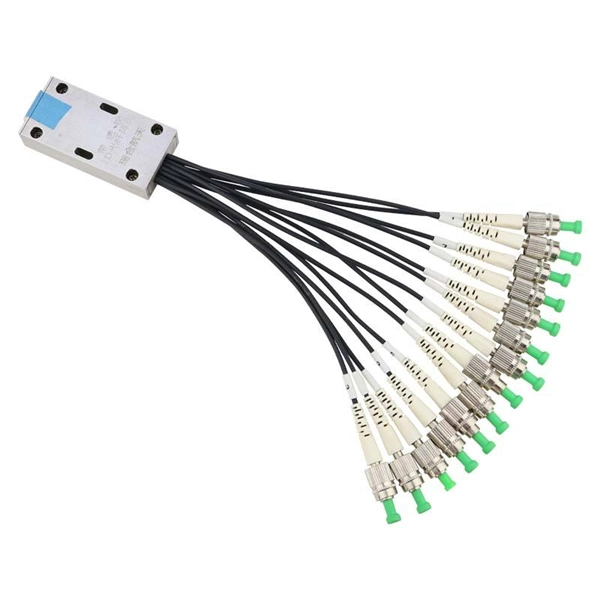
The fiber optic distribution box accomodates up to 6 core fibers and supports outdoor applications within FTTH network system. The type of installation for 6 core distribution box is wall-mounted. The entry size of the drop cable is perfectly designed to accommodate 2x3 millimeters. Serves as a critical termination and distribution point in FTTH networks, offering mechanical protection for fiber optic connections. Ideal for both indoor (residential buildings, offices) and outdoor (exterior walls, utility areas) environments, ensuring durability in diverse conditions. The enclosure supports fiber splicing, splitting, and distribution within a single compact unit, ensuring organized cable routing and secure fiber. [Flexible Flip Board Design] The rotatable flip board allows for up to 180 degrees of flipping, enabling easy angle adjustments during use. [Robust Material] Constructed with abs material, this fiber distribution box offers excellent toughness, strength, wear, and impact. [Minimal Optical Loss]. FBR-11606 Fiber-Optic Distribution Box, 6-Core is a high quality product by Bud Industries used for electronic enclosure applications. It's easy to splice, split and manage the fiber in the box. FDB can provide solid protection and easy maintenance for FTTx network construction.
[PDF]
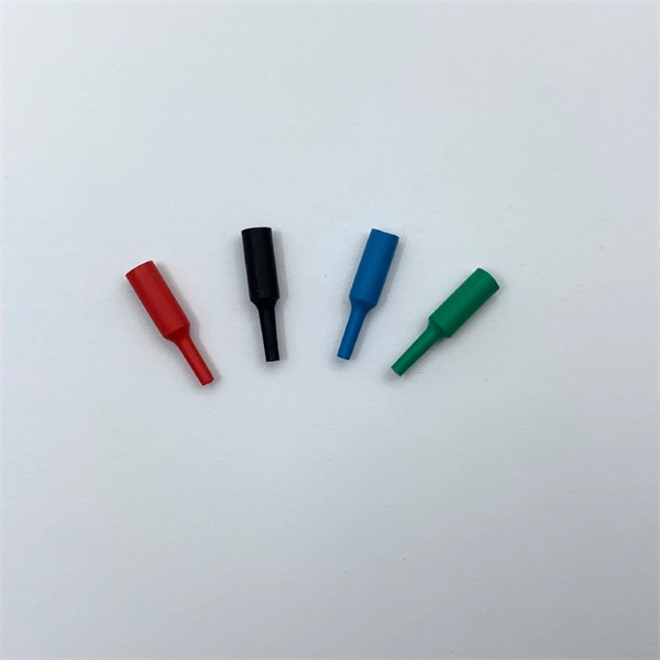
The answer has to do with the connector endface polish, or the angle of connection, and the good news is connectors also follow industry-standard color codes. Fiber connectors are often used as the terminations of optical fiber cables to provide non-permanent connections between fiber-coupled devices (a kind of removable fiber joints). They are used in a similar manner as electrical connectors. This allows for quickly connecting and disconnecting of fiber optic cables without splicing. The connector features a ferrule, the connector end piece that holds and secures the fiber and aligns it for light. The fiber connector is called a fiber optic or optical fiber connector. A link's transmit signal (Tx) must match its corresponding receiver (Rx) at the other end. Although it may seem obvious, fiber optic polarity is a frequent source of confusion and. Fiber optic patch cables consist of the connectors on the ends of the fiber cable. The options on these cables dictate the fiber type, connector type, polarity, and polish type. The fiber types are SMF (Single-mode fiber) and MMF (multimode fiber). The most common connector types are LC, SC. The fiber connector types, sometimes referred to as terminations, link fiber optic cables together through terminals, switches, adapters, and patch panels, by bridging the gap between their internal glass fibers that transmit the data down the length of the cable. The ferrule, a cylindrical.
[PDF]
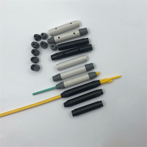
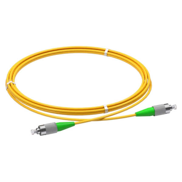
Get the wrong connector type, the wrong polish, or skip proper fusion splicing technique—and you're looking at elevated signal loss, increased back reflection, and a field termination that fails certification. Once you nail the logic chain— raw fiber → protected cable → spliced pigtail interfaces → flexible patching —you control loss budgets, installation time, and maintenance risk. Key takeaway: Treat the four items like a relay team. Each runs a specific leg so your network hits performance targets. In the intricate ecosystem of fiber optic networks, two components play a critical role in ensuring seamless connectivity: patch cords and pigtails. While both are essential for linking fibers to devices or other cables, they serve distinct purposes and are designed for specific scenarios. Executive Summary: A fiber optic pigtail is one of the most commonly specified yet least understood components in structured cabling. Despite their widespread use and numerous advantages, there are some circumstances in which they might not be the ideal option. A fiber optic pigtail is very practical for on-site terminations where fusion or mechanical splicers are used. Preterminated connectors offer several advantages over. Today, I'll show you how to pick the right patch cord or pigtail — step by step. A Fiber Patch cord connects two devices. You plug it into a switch, router, or patch panel. It's ready to use out of the box. A pigtail is for splicing.
[PDF]
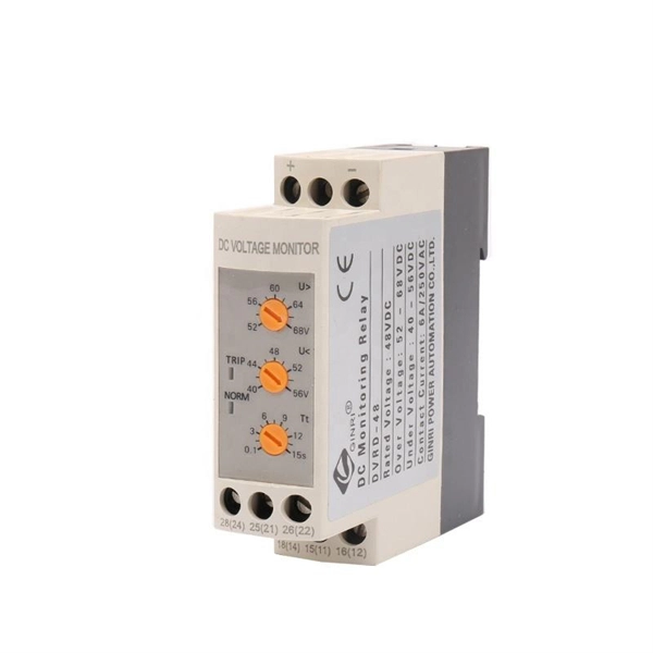
This guide will equip you with a systematic approach to diagnosing and resolving the most common optical link performance issues. By understanding the root causes, you can minimize downtime and ensure your network operates at its peak efficiency. When issues like signal loss, slow speeds, or intermittent connectivity arise, systematic troubleshooting is key. Why Do Fiber Networks Fail? Despite their robustness, fiber networks can fail due to:. This document describes how to troubleshoot fiber optic interfaces by addressing some of the fiber optic module and cabling specifications. There are no specific requirements for this document. The information in this document is based on all Catalyst 9000 Series switches. This includes Doppler. Fiber optic troubleshooting is an essential skill for network administrators, technicians, and engineers responsible for maintaining and repairing fiber optic systems. I switched to ATT fiber from Xfinity because usually fiber optic is faster. However I've had fiber optic for 2 days, and my gateway is constantly disconnecting from the network. I know the technician said something about. Optical fiber networks are essential for delivering high-speed internet and reliable communication. Despite their advanced technology, these networks can encounter problems that impact performance. Effective troubleshooting is crucial to maintaining a smooth and efficient network. This blog post.
[PDF]
Typical rates range from $75 to $180 per hour per technician, with on-site time often dominating the total. Hidden costs include traffic control, trench restoration, and post-repair verification testing. Prices for fiber optic repair vary by issue type, location, and required work. This guide lays out cost expectations, with clear low–average–high estimates and regional nuances. Includes fusion/splice, testing, and basic materials. This guide provides practical cost ranges in USD with. In the United States, fiber optic repair typically costs a few hundred to several thousand dollars, depending on the scope of the fault, distance of the fiber run, and required components. The cost to fix a fiber line often hinges on the fault type, distance, and response time, with price ranges reflecting differing crews and materials.
[PDF]

Optical splitters enable a signal on an optical fiber to be distributed among two or more fibers. Since fiber splitters contain no electronics nor require power, they are an integral component and widely used in most fiber-optic networks. A fiber optic splitter is a passive optical component that divides a single incoming optical signal into two or more outgoing signals, or combines multiple incoming signals into one. Unlike active devices (which require power), splitters operate without electricity, relying solely on the physics of. Optical cables, also known as fiber optic cables, consist of thin strands of glass or plastic fibers surrounded by a protective casing. These fibers transmit data as light signals, which are converted into electrical signals at the receiving end. The benefits of optical cables are numerous. A fiber-optic splitter, also known as a beam splitter, is based on a quartz substrate of an integrated waveguide optical power distribution device, similar to a coaxial cable transmission system. Its primary role is in Passive Optical Networks (PON), which are the foundation of. A fiber broadband provider typically determines and overall split ratio for the network, such as 1x32 or 1x64, and uses combinations of splitters to meet that ratio with each PON port. 1x32 splits were common in North America for G-PON architectures. As XGS-PON continues to be adopted, some service.
[PDF]
The short answer is no - RJ45 connectors are designed for electrical Ethernet signals, while fiber optics transmit light pulses through glass or plastic. However, modern networks often combine both technologies. With the launch of the new Wi-Fi 7 routers BE800 and BE900, our home routers have begun to utilize the high speeds that come with added SFP+ Compatibility. The SFP+ port is a high-speed optical-to-optical signal conversion port, mainly used for 10G Ethernet and Fiber Channel network applications. A. Small Form-factor Pluggable (SFP) is a compact, hot-pluggable network interface module format used for both telecommunication and data communications applications. Think of it as the “translator” for your network equipment, converting electrical signals into optical signals. SFP (Small Form-factor Pluggable) modules, also known as mini-GBICs (Gigabit Interface Converters), are commonly used in network switches and routers to provide flexible and modular network connectivity options. These types of ports can be used with various transceivers thereby allowing the system administrators to customize connectivity according to their network topology. SFP modules and DAC cables are used inside SFP28/SFP/SFP+ slots on UniFi or client devices. These slots allow for versatile connectivity options using different types of cabling. SFP+ and SPF28 DAC Cables: Establishing 1/10/25 Gbps connections over short distances, e. between devices in the same.
[PDF]
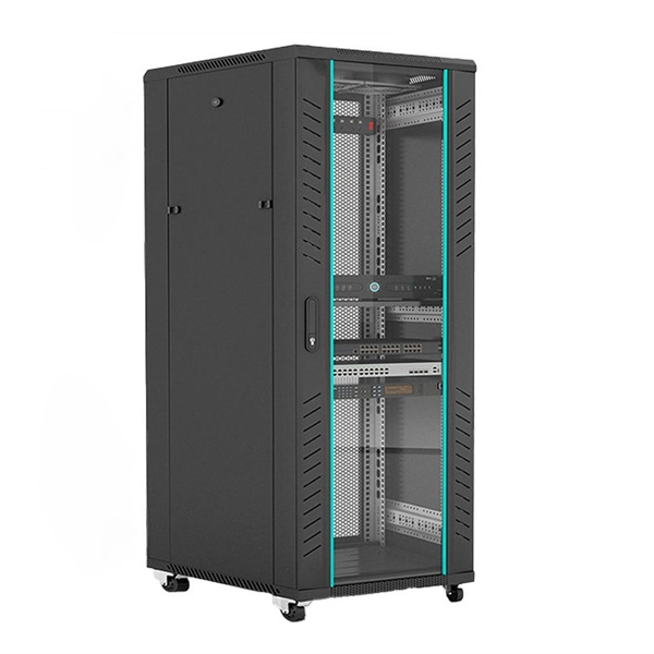
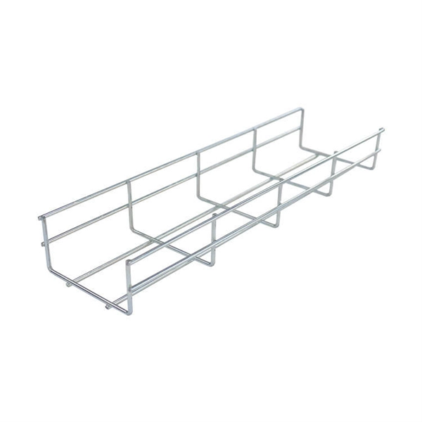
This complete guide explores everything you need to know about ODFs — from their structure, types, and key components, to installation best practices and modern design trends. Whether you're building a central office, data center, or FTTx distribution network, understanding the right ODF. In modern data centers and enterprise networks, Optical Distribution Frames (ODF) serve as the backbone for organizing, terminating, and managing fiber optic connections. This article explores the types, components, applications, installation, and maintenance best practices, providing a. An Optical Distribution Frame (ODF) is the central hub for fiber splicing, termination, patching, and cable protection in modern optical networks. As data centers, enterprises, telecom operators, and smart-building infrastructures deploy increasingly dense fiber links, ODFs provide the structured. Achieve successful cable management, handle high amounts of fiber cable and add density to fiber frames with the new DCX Optical Distribution Frame (ODF) System which features innovations like flippable cassettes, modular frame design and multiple configuration options. The ODF System Components. Optical distribution frames (ODFs) are an all-important network element at the heart of a fiber network. They provide efficient fiber optic management, connectivity, and protection.
[PDF]
Picking up the best router for fiber internet isn't just about going to the market and choosing one of the best wireless routers. Instead, you need to carefully look at its specs, performance, and the type of securit.
[PDF]
The projected fiber optic splicer job growth rate is 6% from 2018-2028. About 13,600 new jobs for fiber optic splicers are projected over the next decade. — (September 22, 2025)—Today the Fiber Broadband Association (FBA) and NCTI, a leading broadband and network training solutions provider, unveiled the results of a joint workforce preparedness survey. The findings have been published in a paper titled, “Employer Workforce. The fiber optic splicer market is experiencing robust growth, driven by the expanding global telecommunications infrastructure and the increasing demand for high-speed internet connectivity. The market's Compound Annual Growth Rate (CAGR) is estimated at 7% for the period 2025-2033, indicating a. Government broadband funding is flowing, but the technicians and engineers to build fiber networks don't exist in sufficient numbers. Telecoms are getting creative with recruiting. The Bipartisan Infrastructure Law allocated $42. 5 billion for broadband deployment through the BEAD program. State. Data-driven look at fiber optic and broadband technician careers, including the 178,000-worker shortage driven by $42. 5B in federal broadband investment, salary data, certification paths, and why this may be the best-timed trade career in a generation. Fiber network deployments in the US, while hitting a bit of a slowdown, are proceeding apace and will ramp up significantly as grants start.
[PDF]
A variety of optical fiber connectors are available, but SC and LC connectors are the most common types of connectors on the market. Typical connectors are rated for 500–1,000 mating cycles. The main differences among types of connectors are dimensions and. An optical fiber connector is a device used to link optical fibers, facilitating the efficient transmission of light signals. They come in various types like SC, LC, ST, and MTP, each designed for specific. Fiber connector types LC, SC, FC, ST, MTP, and MPO are widely used in past and present. What are the differences between them? Who is the most popular one? Find the answer in the article. What is a Fiber Connector? The optical fiber connector is a kind of detachable passive optical component used. Fiber optic cable assembly quality hinges on selecting the right connector type—most commonly LC, SC, or ST—to match device ports and installation environment. When selecting the appropriate optical module for a network application, one crucial factor to consider is the type of fiber connector it employs. Fiber optic connectors are used to the mechanical and optical means for cross connecting fibers. There have been many types of connectors developed for fiber cable. With the demands of different application scenarios.
[PDF]
The os3150 and os3155 are rugged, spot-weldable optical strain gage based on fiber Bragg grating (FBG) technology, with optional integrated temperature compensation. The os3100 Optical Strain Gage is designed to make fiber handling easy and sensor installation fast and repeatable. Its stainless steel carrier holds the FBG in tension, using no epoxy. SCAIME has developed a complete range of fibre-optic strain gauges for monitoring complex structures. Since there are no. What are Optical Strain Sensors? Optical strain sensors (or strain gauges) are sensors for compressive and/or tensile mechanical strain (deformation) which are based on optical technology — in most cases, on fiber optics. They can be based on different operation principles as explained in the. Fiber Bragg grating strain gages can be delivered pre-laminated for measuring strain on stiff surfaces. They are suitable for being fixed easily onto the measurement object, like concrete beams, or rocks. These sensors possess great sensitivity and reliability, which explains their growing popularity across various engineering and monitoring applications. The fiber optic strain gauge is directly attached onto the.
[PDF]
This guide compares the main eLife plans and Neo/Neo Fusion options, explains key numbers like Mbps vs Gbps and real-world performance, and shows where promotions (Amazon Prime, TV packages, Smiles Points, free installation) can change the value of a subscription. Only 4 left in stock - order soon. TLG F1110SB 25A/B Fiber Optic Ethernet Media Converter, Singlemode 10/100Base TX to 100Base FX, RJ45 to SC, Fiber Optic Transceiver Up to 25KM. Linksys Velop. Phone : 04 28. Leading. With TP-Link routers you get a stable, efficient and effective high speed internet connectivity while providing safety and security. You can shop from a range of TP-Link routers for your home or office online on Sharaf DG. Giving you a seamless internet connectivity for your binge watching. Welcome to our comprehensive guide on finding the best fiber optic cable suppliers and installation services in the UAE. At Al Hutaib, we understand the importance of a reliable and efficient fiber optic network for businesses and individuals in the UAE. Our goal with this article is to provide you. Types of routers: wired routers, wireless routers, core routers, edge routers. Integrated security features. Free remote installation support. There are no reviews yet. Buy Cisco Routers Online at the Best Prices in UAE. Find networking devices for sale, ideal for business use, in Dubai and across the UAE.
[PDF]
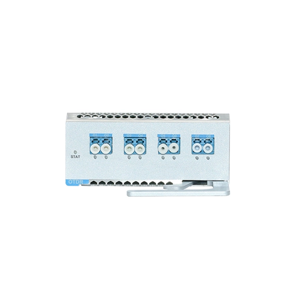
This simple step resolves many issues with sfp optical transceivers in access switches and core routers. Test with a known-good module or patch cable. If the issue persists, suspect either the switch port or external fiber path. Read TX/RX power, bias current, voltage, and. Optical transceivers play a crucial role in modern data communication networks, enabling the transmission and reception of optical signals across fiber-optic cables. However, like any other electronic component, optical transceivers can encounter issues that may affect network performance. This guide. This guide provides a deep technical overview of how to troubleshoot sfp optical transceivers and other optical transceivers module types effectively in 2025. These compact devices convert electrical signals to optical signals and vice versa, enabling data transmission over fiber optic cables. We'll discuss how to identify the issue, possible causes of optical transceiver issues, troubleshooting steps, and. Have you ever experienced an unexpected network outage due to the failure of an SFP/SFP+ optical transceiver? Network outages can bring your ability to communicate and work to a halt, and your IT team will likely be frantically looking for a solution. It is important to understand how to.
[PDF]