One-line diagrams and detailed network data (lines, transformers, buses). Short-circuit models, including fault current calculations under various system configurations. Protective relay settings and coordination curves. Historical. presentation of protection and control relaying. The report will identify methodology behind these practices, present issues raised by the integration of microprocessor relays and the internal logic and external communication configurations, ying. Schematic diagrams of protection relays are essential tools for power engineers in the power generation, transmission, and distribution industry. This includes AC schematics and DC schematics and diagrams that prominently feature relaying. There are other equally important types of drawings that are not the subject. Power System Protective Relays: Principles & Practices Presenter: Rasheek Rifaat, P. Eng, IEEE Life Fellow IEEE/IAS/I&CPSD Protection & Coordination WG Chair Jacobs Canada, Calgary, AB rasheek. com IEEE Southern Alberta Section PES/IAS Joint Chapter Technical Seminar - November 2016. Recognized under 2(f) and 12 (B) of UGC ACT 1956 (Affiliated to JNTUH, Hyderabad, Approved by AICTE - Accredited by NBA & NAAC – 'A' Grade - ISO 9001:2015 Certified) Maisammaguda, Dhulapally (Post Via. Kompally), Secunderabad – 500100, Telangana State, India To introduce all kinds of circuit.
[PDF]
In telecommunications, an eye pattern, also known as an eye diagram, is an oscilloscope display in which a digital signal from a receiver is repetitively sampled and applied to the vertical input (y-axis), while the data rate is used to trigger the horizontal sweep (x-axis). It is so called because, for several types of coding, the pattern looks like a series of eyes between a pair of rails. It is a too. CalculationThe first step of computing an eye pattern is normally to obtain the waveform being analyzed in a quantized form. This may be done by measuring an actual electrical system with an oscilloscope of sufficient bandwidth,. Each form of baseband modulation produces an eye pattern with a unique appearance. The eye pattern of a signal should consist of two clearly distinct levels with smooth tra. Many properties of a can be seen in the eye pattern. applied to a signal produces an additional level for each value of the signal, which is higher (for pre-emphasis) or lower (for de-emp.
[PDF]
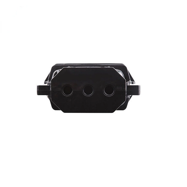
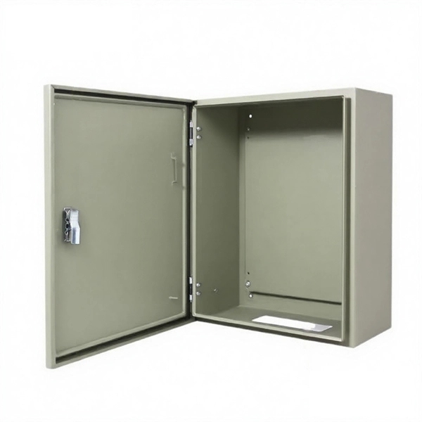
This AutoCAD DWG file includes a complete Single Line Diagram (SLD) of a Distribution Board, showing circuit breakers, wiring connections, and load distribution for lighting, power, and mechanical systems. An electrical panel box, also known as a breaker box or a distribution board, is a crucial component of any electrical system. It serves as a central hub for distributing electricity throughout a building, ensuring that power is delivered safely and efficiently to all the required locations. And all the switching and protective devices are installed in the. A distribution box is a key part of electrical systems in buildings. Inside, you'll find parts like circuit breakers and fuses that protect the system from problems like overloads and short circuits. Today, electrical systems are essential for homes and industries. Electrical Distribution board is used for controlling of utilization of power in the end point like as lighting circuit, power circuit and other equipment like as TV, fridge and airconditioning. The incomer supply is received from distribution panel. In this board, balance load is distributed as.
[PDF]
Download a comprehensive set of Cable Tray Installation CAD Blocks in DWG format, ideal for electrical engineers, MEP designers, and industrial layout planners. This article shares simple ways to plan your cable trays and wiring. We want to help electrical engineers, technicians, and anyone working with electrical setups build safe and good systems. This collection includes installation details for ladder trays, perforated trays, solid-bottom trays, and wire mesh trays, along with. This guide provides step-by-step instructions on installing a cable tray on a wall, covering different types of cable trays, tools needed, and safety tips. The Ladder Tray features light, rugged, tubular steel construction. It is designed for. In industrial settings, electrical and instrumentation (E&I) cable trays or bridge racks play a critical role in organizing and supporting power, control, and signal cables across facilities. An effective layout ensures safety, minimizes interference, reduces maintenance time, and keeps the overall. ALL TO BE CLEANED WITH A COMMERCIALLY AVAILABLE CLEANSER PRIOR TO ALL MARKERS AFFIXED PRIOR TO INSTALLATION OF ANY CABLE. BONDING JUMPER SHALL BE INSTALLED FOR ELECTRICAL CONTINUITY ACROSS ALL DETAIL AT INTERFACES AND/OR CONDUIT BUSHINGS SHALL INSTALLED FCR ENTRY OF CABLES.
[PDF]
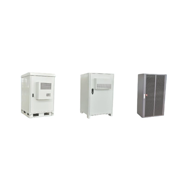
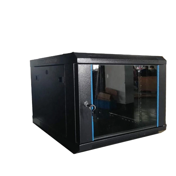
They are characterized by numerous ports and high bandwidth, offering greater reliability, redundancy, throughput, and lower latency compared to access and aggregation switches. For a network with over 100 computers, a core switch is indispensable for ensuring stability and high. Data center-grade switches are characterized by high-quality business assurance and control recognition capabilities. They feature end-to-end flow control and backpressure mechanisms, ensuring stable and reliable data transmission, and smoothing out network surges. They offer higher reliability and. Aggregating Data Traffic: Accumulates data from the distribution and access layers and manages their routing and switching. High Performance: Guarantees dependable and quick data delivery, supporting substantial traffic with low latency. Redundancy and Fault Tolerance: This feature ensures network. A Core Switch is a critical device that operates in the backbone portion of a network, primarily used for high-speed data switching. It is part of the commonly used Network Switch hardware architecture and serves as a port device in the core layer.
[PDF]
Energy & Financial Markets: What Drives Crude Oil Prices? Greenhouse gas data, voluntary reporting, electric power plant emissions. Maps, tools, and resources related to energy disruptions and infrastructure. State energy information, including overviews, rankings, data, and. Energy is at the heart of today's geopolitical tensions, with traditional risks to fuel supply now accompanied by restrictions affecting supplies of critical minerals. International. The IEA examines the full spectrum of energy issues including oil, gas and coal supply and demand, renewable energy technologies, electricity markets, energy efficiency, access to energy, demand side management and much more. Through its work, the IEA advocates policies that will enhance the. The Energy Institute Statistical Review of World Energy™ analyses data on world energy markets from the prior year. Previously produced by bp, the Review has been providing timely, comprehensive and objective data to the energy community since 1952. By submitting your email you agree to receive. Reducing energy consumption and achieving energy savings is essential to deliver the European Green Deal. Energy from renewable sources reduces greenhouse gas emissions and lowers our dependence on imported fossil fuels.
[PDF]
This research investigates the strain transfer characteristics of embedded FBG in pavement structure and materials by using the relevant theoretical models. Results indicate adhesive layer thickness and sheath modulus are the primary factors influencing the strain transfer coefficient. Fiber Bragg Grating Sensors (FBGS) are gaining increasing attention in the field of experimental stress analysis. They are very well suited to the new materials of glass and carbon fiber reinforced composites which are often used for highly stressed constructions, e. in airplanes and wind power. Fiber Bragg grating (FBG) exhibits strong resistance to electromagnetic interference and excellent linear strain response, making it highly promising for structural health monitoring (SHM) in pavement. The samples were made by the direct pressing method from fiberglass prepregs. Strain sensors based on FBGs are becoming an essential part of smart factory. Due to the difference in the physical and mechanical properties between the optical fiber, protective layer, adhesive layer, and the host material, the strains measured by a fiber Bragg grating (FBG) sensor may not be the actual strains of the host material, which impedes the reliable applications. Fiber Bragg Grating Sensors (FBGS) are gaining increasing attention in the field of experimental stress analysis. in airplanes and wind power.
[PDF]
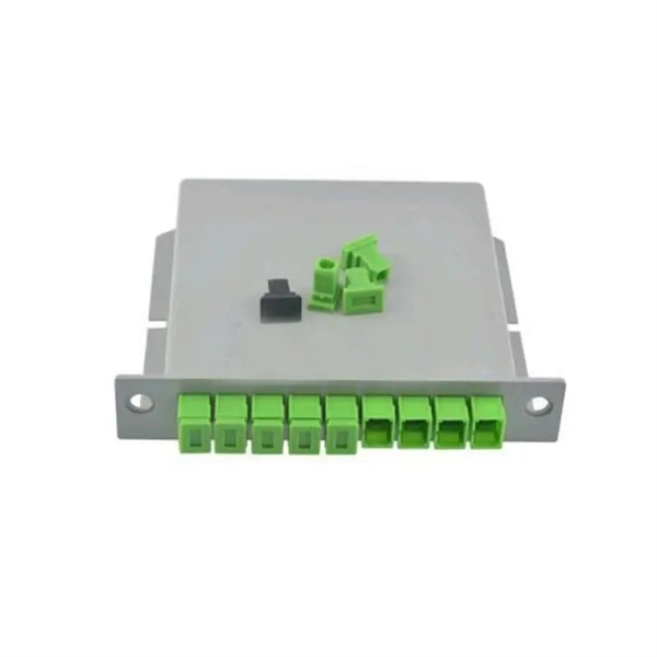
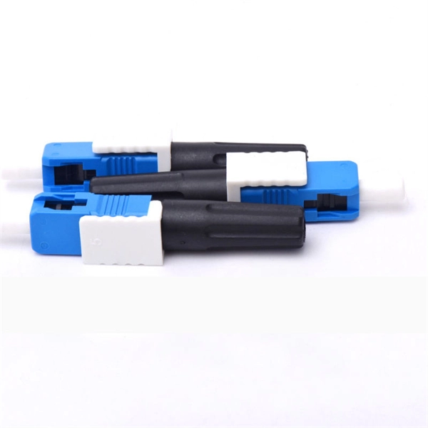
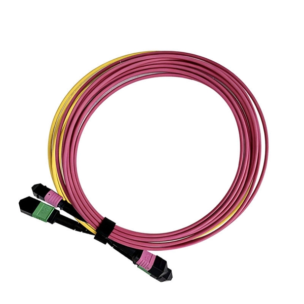
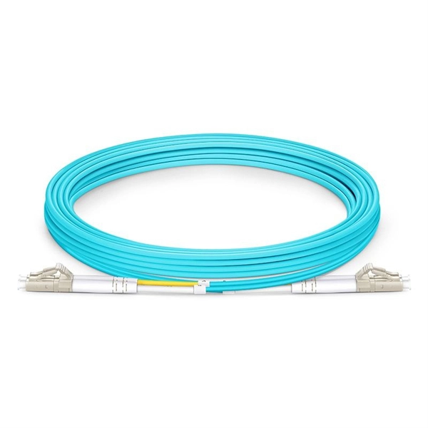
This guide will help you understand how to evaluate suppliers and make an informed decision when sourcing fiber optic patch cords for your projects — from FTTH deployments and Data Centers to Industrial Networks and Telecommunications Infrastructures. The Global Waterproof Fiber Patch Cord Market size was valued at USD 805. 2 Million in 2025 and is anticipated to expand consistently, reaching USD 885. This impressive rise indicates a CAGR of 10. Market research provides details on what people want (demand) and what's available (supply). This market is expected to grow by 9. 8%% each year, from 2026 to 2033. Tip: Many high-quality fiber patch cord. Introduction of Waterproof Fiber Patch Cord and its Technical Aspects A waterproof fiber patch cord is a specialized type of fiber optic cable that is designed to withstand exposure to water and other moisture. It is commonly used in outdoor or harsh environment applications where the cable may be. Waterproof Fiber Patch Cord by Application (Network, Telecommunications, Military and Aerospace), by Types (Single-mode Fiber Optical Patch Cord, Multimode Fiber Optical Patch Cord), by North America (United States, Canada, Mexico), by South America (Brazil, Argentina, Rest of South America), by.
[PDF]
Trapezoidal Cable Tray: Trapezoidal cable trays are characterized by their trapezoidal structure consisting of two side rails connected by a crosspiece. This design allows for excellent ventilation and heat dissipation, making them ideal for high-capacity cable management. Fiberglass - Technical Data Structural Characteristics of Cable Tray and Supports When viewed in its installed condition, any cable tray system performs functionally as a beam under a uniformly distributed load. There are four basic beam configurations typically found in a cable tray installation. -piece tray istypically used in applications where visual esthetics are important. It is available with a ventilated or solid bottom. Channel tray can protect against. Steel cable trays come in various types, each offering unique features and catering to different applications. Among them, the stainless steel cable tray is highly recommended for use in the petroleum, chemical as well as television industries. Its lightweight nature, elegant appearance, easy. This appendix provides the design criteria for seismic Category I cable trays and their supports. Seismic Category II cable trays and their supports are also designed utilizing the design criteria of this appendix. These trays have large space and good ventilation performance. Structural Design and Flexibility: The structural.
[PDF]
Simple 3-phase distribution board wiring diagram for home use, showing safe connection of power supply, breakers, neutral, and earth for residential electrical systems. Hey, in this article we are going to see the Three (3) Phase Distribution Board Wiring Diagram and Connection Procedure. The three-phase distribution board is used to distribute power to the three-phase loads and circuits such as three-phase motors, three-phase machinery, three-phase to. In a newly constructed residential area, a 10kV power line is introduced into the substation. After stepping down the voltage through the transformer's low-voltage side (0. The following is a detailed introduction about it: - **First-level Distribution. Utilities may have some control over and access to the energy stored in electric vehicles attached to the grid. ndards and conformity assessment activities in the United States. ANSI facilitates and promotes voluntary consensus standar rty or economic loss due to fire, electrical and related hazards. They deliver information and knowledge through more than 300 consensus codes and nspection to protect people.
[PDF]
To find the best routerfor fiber internet, we used our expertise to select items based on key specs, such as speeds, coverage, wireless standards, security, weight, and additional features. We've also delve.
[PDF]