This video shows 2D wave simulations of optical fibers and presents differences between single-mode and multi-mode light propagation. more Audio tracks for some languages were automatically generated. Learn more. This applet is called FIMOC (fiber-optic mode online calculator). With it you will be able to calculate and visualize the propagating modes of any step-index fiber of your choice. If you want to go directly to the software, scroll to the bottom, but if you are interested in where these modes come. Optical fiber sensors have attracted significant interest in the sensing field. This paper presents a C-shaped optical fiber sensor sensitivity enhancement through design. RP Fiber Power is a powerful software for simulation, design and optimization of fiber devices — in particular, fiber amplifiers and lasers as well as other types of waveguide lasers (and even many bulk lasers), but also fiber couplers, multi-core fibers, helical core fibers, tapered fibers and. In this proposed workflow, we couple Ansys Mechanical TM with Ansys Lumerical TM, creating an innovative workflow that can detect the position of a random mechanical strain along an optical fiber. In this proposed workflow, DFOS utilizes standard single mode optical fiber as a sensing element. 1Department of Mechanical and Aerospace Engineering, University of Texas at Arlington, 500 W.
[PDF]
In fiber-optic communications, wavelength-division multiplexing (WDM) is a technology which multiplexes a number of optical carrier signals onto a single optical fiber by using different wavelengths (i.e., colors) of laser light. This technique enables bidirectional communications over a single strand of fiber (also called wavelength-division duplexing) as well as multiplication of capacity. The. SystemsA WDM system uses a at the to join the several signals together and a at the to split them apart. With the right type of fiber, it is possible to have a device that does both s. Originally, the term coarse wavelength-division multiplexing (CWDM) was fairly generic and described a number of different channel configurations. In general, the choice of channel spacings and frequency in these co.
[PDF]
It enables uniform, shadow-free lighting by directing light along the same optical axis as the lens. When integrated into specialised lenses, the beam splitter divides the incoming light into two paths: one beam illuminates the object, while the other is used for image capture. Beamsplitters are fundamental components in optical engineering, serving to precisely divide a single input beam of light into two distinct output beams. This division allows for the simultaneous analysis or utilization of the light's properties along two separate paths. Additionally, beamsplitters can be used in reverse to combine two different beams into a single one. In practice, the reflective layer absorbs some light. It is a crucial part of many optical experimental and measurement systems. A cube beam splitter is, at its essence, an optical device that splits an incoming light beam into two sections. What are beamsplitters and how are they used in optics and photonics applications ? Beamsplitters are optical components that are used to. The beam splitter splits and then recombines infrared radiation, while the detector picks up the resulting signal. It's sensitive to both intensity and frequency. Together, they decide just how accurately an instrument captures those unique infrared “fingerprints” from different substances.
[PDF]
Typically made of glass, a beam splitter divides the light passing through it at a ratio. Usually, half of the light is reflected at an angle, and the other half is transmitted to the opposite side of the light source. A beam splitter or beamsplitter is an optical device that splits a beam of light into a transmitted and a reflected beam. It is a crucial part of many optical experimental and measurement systems, such as interferometers, also finding widespread application in fibre optic telecommunications. This division allows for the simultaneous analysis or utilization of the light's properties along two separate paths. a laser beam) into two (or sometimes more) beams, which may or may not have the same optical power (radiant flux).
[PDF]
The worker must then connect one end of the fiber optic cable to a light source. Then, once they have done this they will turn on the light source and press the button on the. When it comes to testing fiber optic cables, a Visual Fault Locator (VFL) is an essential tool in your toolkit. A VFL is used to detect faults, breaks, or bends in fiber optic cables by emitting a bright red light that is visible even through the fiber's jacket. It's a cost-effective and. How to use fiber optic red light pen? It can be seen from the above that the red light pen has many uses, but its most common use is to detect the connectivity of the optical fiber and locate the fault point of the optical fiber. more How to use a VFL to identify a fiber optic cable from end to end. Viavi VFL:https://amzn. to/3L7cL6RTools I use:3 Hole Strippershttps://amzn. Within the pen, a small but powerful laser sends out an intense red light. Here is how the pen helps detect errors. If the fiber optic cable is appropriately intact and. The RPEN-210 is a necessity tool that should not be missing from any fiber plant manager or fiber optic installing technician. The Visual Fault Locator (VFL) Pen has a visible red light source centered on 650nm. Tool sends visible light over a fiber strand with a 10mW power, good enough to reach.
[PDF]
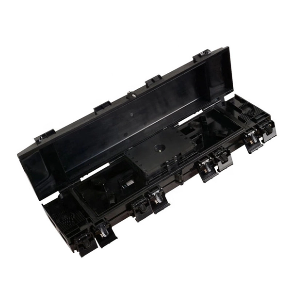
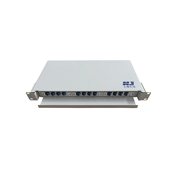
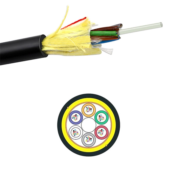
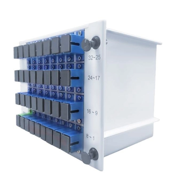
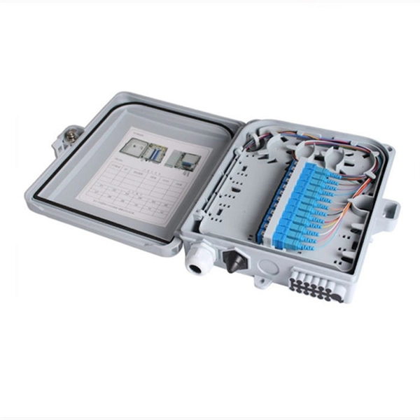
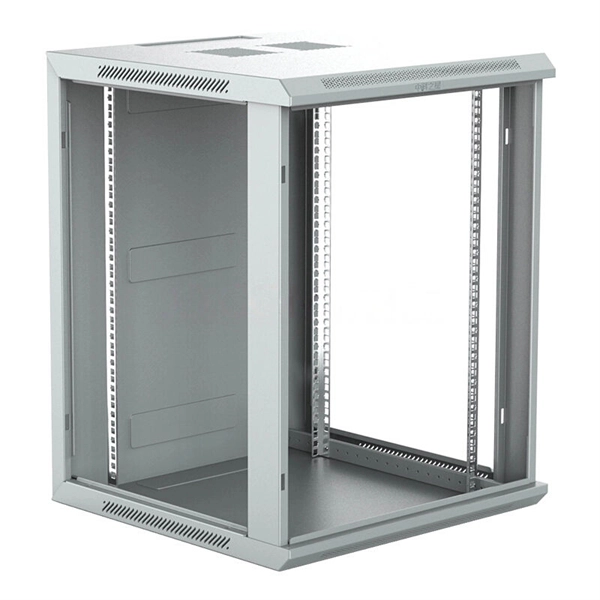
Through the adapter in the distribution box, the optical signal is led out by the optical jumper to realize the optical wiring function. An optical cable consists of three primary parts: the core, the cladding, and the protective sheath. The core is at the center of the optical cable and serves as the pathway for transmitting light signals. Surrounding the core is the cladding, which has a lower refractive index than the core. In the complex architecture of fiber optic networks, the Optical Distribution Frame (ODF) serves as the linchpin for organizing, protecting, and distributing optical signals. Whether in data centers, telecom central offices, or enterprise network rooms, ODFs enable efficient fiber management. The optical fiber distribution box is to protect the connection point where the optical cable is connected to the user end, so that the optical cable access point is stable, dustproof and waterproof. What is a fiber distribution box? 2. The. A fiber distribution box (FDB) functions as a central hub in fiber optic networks where the main cable is split into multiple individual fibers for distribution to end users. These boxes protect sensitive fiber connections from environmental factors while providing an organized framework for.
[PDF]
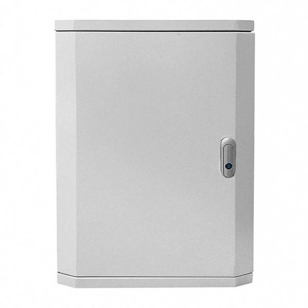
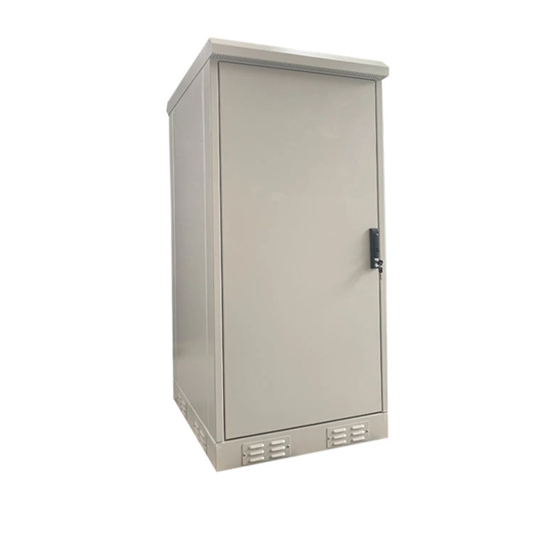
Find reliable optical fiber distribution frame prices for various needs. Shop high-quality, durable ODFs and patch panels for efficient communication networks. Understanding the landscape of main distribution frame (MDF) pricing is crucial for network architects and procurement professionals. The market is dynamic, influenced by technological upgrades and shifting demand across industries. Strategic purchasing requires a clear view of these forces. Pre-terminated ODFs with cables are pre-installed with connectors and cable for quick and easy installation. Units with pre-terminated cables offer. Fiber distribution box is suitable for the wiring connection of optical cable and optical communication equipment, through the adapter in the wiring box, the optical jumper leads the optical signal, and realizes the optical wiring function. OTRANS strives to provide you with professional, reliable. Max. Capacity: Company Info. Capacity Once receive your question, the supplier will answer you as soon as possible. Enter between 20 to 4,000 characters. The fibre optic distribution frame is a high-capacity fibre distribution frame designed for fibre termination, cross connection, and distribution in optical access networks. It enables efficient connection, routing, and management. HIGH DENSITY FLOOR STANDING. This fiber optic distribution.
[PDF]
The Light Cube can be dyed using any color cube. Upon merging, it adopts the color of the cube used. Each dye attempt increases a dye counter, tracking how many times it's been recolored. 💡 Note: These items transform when fused with a Light Cube. The glow effect varies based on dye count. or if you want to see a video, then here: https://www. Each dye. This is a light cube DIY kit that you need to weld and assemble by yourself. The bottom plate comprises a circuit board and component parts. The 512 LED lights make up a stereo space. A variety of cool model showing a three-dimensional effect. It's better to watch in the night. Installation Manual:. 8x8x8 LED Cube Kit DIY Electronic Kit Soldering Project Kit, User Needs to Solder The LED, and The Displayed Content Can Be Modified. (GZT-64) Shop products from small. The dot matrix component features 25 RGB color light clusters, arranged in a 5x5 grid. Each individual light bead offers 16000K color variations, all of which can be controlled via an APP. When these 25 light beads come together, they provide an infinite array of color possibilities. It can craft some pretty decent weapons and it can make my favorite structure, Lantern! I hope you enjoy! :D. A light source has been placed inside to create interesting shadows. The pieces in this project can connect to each other without using any glue (however using glue.
[PDF]
Wavefront shaping enables precise control of light propagation through multimode fibers, facilitating diffraction-limited focusing for applications such as high-resolution single-fiber imaging and high-power fiber amplifiers. While the theoretical intensity enhancement at the focal point is. Light from a high-power laser diode is coupled into a multi-mode fiber (diam:100 um, NA = 0. A de-speckle unit can be turned on and off to reduce any speckles that appear after light leaving the multi-mode fiber. A collimating lens (CL) after the fiber collimates the light to a certain. We present laboratory measurements demonstrating how the output beam profile from multimode fiber can be affected by the beam entry angle. In some applications, an alternative beam distribution such as a top hat or donut is desired instead of the inherent Gaussian distribution provided by typical. Light transport in a highly multimode fiber exhibits complex behavior in space, time, frequency, and polarization, especially in the presence of mode coupling. The newly developed techniques of spatial wavefront shaping turn out to be highly suitable to harness such enormous complexity: a spatial. What are the conditions for efficiently launching light into a multimode fiber? What happens to the intensity profile of light during propagation in a multimode fiber? How do bending and other disturbances affect the output beam profile? What are the challenges of maintaining single-mode.
[PDF]
The AOI impacts the amount of light being reflected and transmitted. For example, most plate beam splitters have an AOI of 45 degrees, which may limit those who need more flexibility. A beam splitter or beamsplitter is an optical device that splits a beam of light into a transmitted and a reflected beam. It is a crucial part of many optical experimental and measurement systems, such as interferometers, also finding widespread application in fibre optic telecommunications. a laser beam) into two (or sometimes more) beams, which may or may not have the same optical power (radiant flux). Their precision and versatility make them indispensable in a variety of scientific, industrial, and technological applications. Beamsplitters are often classified according to their construction: cube or plate. Beamsplitters are fundamental components in optical engineering, serving to precisely divide a single input beam of light into two distinct output beams. This division allows for the simultaneous analysis or utilization of the light's properties along two separate paths. The device is purely. The beam splitter splits and then recombines infrared radiation, while the detector picks up the resulting signal. It's sensitive to both intensity and frequency. Together, they decide just how accurately an instrument captures those unique infrared “fingerprints” from different substances.
[PDF]
Resolving these issues involves steps like checking cable connections, soft resets, updating firmware, and specific solutions for different router brands like ASUS and Spectrum. It often indicates that something is wrong with your internet connection or the device itself. Fortunately, diagnosing and resolving these issues doesn't have to be complicated. In this comprehensive guide, we will walk you through the common causes of a red light on your router and provide. A router showing a red light can mean different things, like a service outage, misconfiguration, or loose connection, all of which can lead to a broken internet connection. Fortunately, there are heaps of ways to fix a red blinking light on your router. One of the first things you should try is to. Turn off the router and disconnect the power cord. Check that the PON cable is free from damage or sprains. Even if you have the best router, you may experience a loss of connection or other issues and see that dreaded red light. When it's green and steady, everything is fine. However, when it blinks red or stays solid red, it signifies a Loss of Signal, a problem preventing your router from communicating.
[PDF]
This comprehensive guide will equip you with the knowledge and steps needed to safely test a lighting circuit using a multimeter. We will cover the essential safety precautions, different testing methods, interpreting the results, and troubleshooting common issues. Understanding the principles. Multimeters are versatile tools used by electricians and hobbyists alike to diagnose electrical problems and ensure the proper function of electrical devices. We'll explain how to measure AC and DC voltage, test for continuity, measure capacitance, measure frequency, and test diodes. Hence the 'multi'-'meter' (multiple measurement) name. The most basic things we measure are voltage. Here is a step-by-step guide on how to test a light fixture with a multimeter for beginners: Step 1: Turn Off the Power Before you begin testing the light fixture, it is crucial to turn off the power to the fixture at the circuit breaker. It's an indispensable tool for troubleshooting and maintaining electrical circuits. Different types of multimeters offer varying degrees of precision and. An easy way to test a light fixture is to remove the bulb and replace it with one that you know is working. If you don't happen to have a working bulb handy, you can use a light socket tester or test the fixture with a multimeter.
[PDF]