We recommend a 'clear space' of 3 ½ inches high, and 4 inches wide on self-mailer pieces. This space is used to display the delivery address, postage, and return address. For folded self-mailers, the fold must be on the bottom or leading edge of the piece. According to the USPS mailing requirements, you have a standard range of dimensions for all your self-mailers. The standard sizes for your self-mailers are mentioned in the table below. Note: It is worth noting that it is okay for your business to use a self-mailer with 0. 009 thickness as long as. The NEC requirements for flush-mounted box installations can be found in Sec. First-Class Mail: 13 ounces. Periodicals: 20 ounces for pieces prepared under 201. A conduit body is a removable-cover section of a conduit system that provides access at junctions or termination points. Article 314 applies to: These. Done right, it ensures safety, compliance, and long-lasting performance. In this guide, we'll break down everything you need to know to install a distribution box correctly and confidently. Choose the right box based on environment (indoor/outdoor), load capacity, and durability. Check for proper. for disconnects, and meter socket enclosures. Notice that these rules cover the cabinets and enclosures that contain electrical equipment su h as panel boards— not the equipment itself ided with a fra for disconnect d telescoping w rfere with succes rs hub, or conn more than 1⁄4 in.
[PDF]
Generally, standard trays require supports every 6 to 10 feet, while heavy-duty, long-span trays can handle distances of up to 20 feet between supports. To determine the proper spacing, consult the manufacturer's load capacity chart, which accounts for the total weight of the. The following are a few points to consider when dealing with cable tray and the National Electrical Code. This is a description of how to select, install, and support these metal or plastic frames, on which electrical wires are installed. You should consider it as a series of instructions that make the buildings resistant to. Support spacing for cable trays must align with the manufacturer's instructions, as outlined in NEC 392. This spacing is crucial for adequate maintenance access, ease of inspection, and ensuring proper airflow for effective heat dissipation. It also helps reduce the risk of. In this installment of our Code Corner series, Ryan Mayfield focuses on the 2023 National Electrical Code (NEC) changes concerning cable trays, particularly section 690. Historically, the NEC has allowed cable trays, but has lacked specific guidelines for sizing conductors and using smaller. This guide covers the critical steps, from selecting the right electrical cable tray and performing accurate cable fill calculations to managing a safe cable pull through and ensuring all bonding and grounding requirements are met. For licensed electricians, mastering these principles is essential.
[PDF]
This document outlines the Philippine Electrical Code (PEC) and its regulatory framework, including laws, objectives, and standards for electrical installations. It emphasizes safety, compliance, and the roles of various government authorities in enforcing these regulations. The Philippine Electrical Code (PEC) is a set of standards and regulations that govern the safe and proper installation, operation, and maintenance of electrical systems in the Philippines. It provides guidelines for electrical design, wiring, equipment selection, grounding, protection, and other. Members of each committee meet several times, discuss proposed changes, accepting some and rejecting others, and rewrite (as required) the sections of the Code that were assigned to their committee. ❑ Regularly revised (every three years) to reflect the evolution of products, materials, and. The purpose of this Code is the practical safeguarding of persons and property from hazards arising from the use of electricity. This Code contains provisions that are considered minimum requirements necessary for safety. Compliance therewith and proper maintenance will result in an. ALL ELECTRICAL WORKS HERE IN SHALL BE EXECUTED IN ACCORDANCE WITH THE LATEST EDITION OF THE PHILIPPINE ELECTRICAL CODE (PEC). THE NEW ELECTRICAL ENGINEERING LAW (R. LAWS AND ORDINANCES OF THE LOCAL GOVERNMENT UNIT AND RULES AND REGULATIONS OF THE LOCAL ELECTRICAL POWER UTILITY COMPANY. Philippine Electrical.
[PDF]
Underground fiber optic cable installation follows specific standards that govern burial depth, testing methods, installation techniques, and safety requirements. Underground cables are pulled in conduit that is buried underground, usually 1-1. 2 meters (3-4 feet) deep to reduce the likelihood of accidentally being dug up. In extreme cold climates, cables may need to be buried at greater depths where there temperatures are colder and frost penetrates to. The Fiber Optic Association, Inc. (FOA) was founded in 1995 to help develop the workforce to build the fiber optic networks to support a rapid expansion in communications and the Internet. The charter of the FOA was to promote professionalism in fiber optics through education, certification, and. This guide walks through each stage of underground fiber installation—from route planning and conduit selection to splicing, termination, and testing—to help ensure long-term network performance and reliability. These standards, established by organizations like the National Electrical Code (NEC), National Electrical Safety Code (NESC), and. Installing underground fiber optic cables is critical to establishing high speed internet infrastructure that delivers reliable connectivity for businesses nationwide. Unlike traditional copper systems, fiber optic cables require specialized handling techniques and precise installation methods to.
[PDF]
This article provides a comprehensive framework that governs various aspects of cable tray installations, including the types of cables that are deemed acceptable for use, requirements for grounding and bonding, and stipulations regarding tray fill capacity. en completely installed, without damage either to conductors or structural system use maintain spacing or to keep cables in place when the tray is ect the minimum bend ra-dius for cables as they exit the bottom of the cable tray. A rung spacing of 6 to 9 inches (150 to 230 mm) is preferable when. The use and installation of cable trays is covered by legally enforceable OSHA regulations in 29 CFR 1910. 305(a)(3), or comparable standards promulgated by States operating OSHA-approved State plans. Additionally, it addresses critical. Article Summary: A compliant cable tray installation requires a thorough understanding of NEC Article 392, proper structural support, and precise installation techniques. This guide covers the critical steps, from selecting the right electrical cable tray and performing accurate cable fill. Instrumentation cable trays are critical for organizing and protecting electrical and signal cables in industrial environments. The following pages address the 2014 National Electrical Code® requirements for cable tray systems as well as design solutions from practical experience. The information has been organized for.
[PDF]
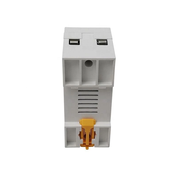
Calculate and select the right number and spacing of cables for junction boxes using NEC guidelines to ensure safe, code-compliant electrical installations. Electrical clearances set the minimum safe distances for panels, overhead lines, pools, and buried wiring — and ignoring them has real consequences. 7* Class A and Class X circuits using physical conductors (e., metallic, optical fiber) shall be installed such that the outgoing and return conductors, exiting from and returning to the control unit, respectively, are routed separately. The outgoing and return (redundant) circuit conductors. Above finished grade or sidewalks, or from any platform or projection from which they might be reached. (If these areas are accessible to other than pedestrian traffic, then one of the other conditions applies). This step keeps your project safe and. In this guide, we'll break down everything you need to know to install a distribution box correctly and confidently. Choose the right box based on environment (indoor/outdoor), load capacity, and durability. Check for proper IP/NEMA ratings and material quality. Ensure safe placement: install in. When looking into electrical panel clearance safety, you need to start by looking at the requirements put in place by the national electric code, or NEC. The relevant section of the national electric code here is NEC 110. This set of code identifies how much clearance is needed around any type.
[PDF]
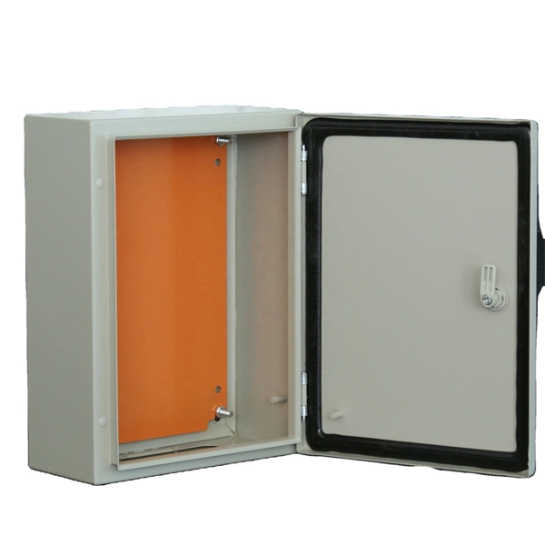
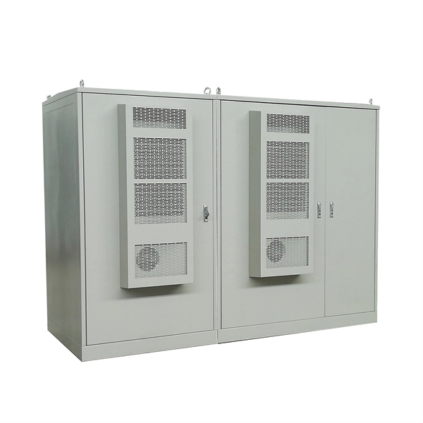
Design requirements for low voltage distribution boxes cover NEC, IEC, and safety standards to ensure reliable, compliant electrical installations. You must make safety your top priority when working with low voltage distribution boxes. Among the most widely recognized frameworks governing electrical panel design are the IEC (International Electrotechnical Commission) standards, particularly the IEC 61439 series, which defines the requirements for low-voltage switchgear and controlgear assemblies. In this blog, we explore the. Standards are for reference only. All new extension or modifications require an approved design and a preconstruction meeting with EWEB prior to installation. Need more information on how to get a design? Contact us at distributionengineering@eweb. NEC Article 408 covers switchboards, switchgear, and Panelboards installation and applications. Redesigned to improve safety, product longevity and appearance over time. Note: Eaton recommends mounting redesigned enclosures with at least six inches of clearance between adjacent structures to provide adequate access to side bolts. a Applicable for type LWPQ only. A distribution box is the heart of any electrical system. It takes the incoming power and safely distributes it to different circuits throughout your building. Whether in a home or an industrial facility, this box keeps.
[PDF]
Find detailed information on Electrical Equipment Manufacturing companies in Argentina, including financial statements, sales and marketing contacts, top competitors, and firmographic insights. Telconet, an Argentine company, specializes in high-technology equipment provisioning and offers structured cabling solutions for voice and data networks, which directly relates to the query about "Wire And Cable. Dun & Bradstreet gathers Electrical Equipment Manufacturing business information from trusted sources to. List of Electrical equipment suppliers in Argentina? There are 371 Electrical equipment suppliers in Argentina as of April, 2026. The highest number of Electrical equipment suppliers of Argentina are in Buenos Aires Province and Buenos Aires with 145 businesses and 56 businesses, respectively.
[PDF]
As shown in the figure below, the main cable consists of three conductor wires extending from the top of the motor flat lead extension to the wellhead banded to the production tubing. The ESP cable carries current (amperage) from the motor controller at the surface down to the motor. CAVALCADE™ ESP power cable meets the high-quality standards required for any oil and gas industry specification–even the most challenging unconventional applications–to deliver the electrical requirements of your ESP and to extend system run life. Get cable built with solid copper conductors. Typically, it is banded or clamped to the production tubing from below the wellhead to the ESP unit because it is not designed to support its own weight. It is a specially constructed three-phase power. Levare is one of few artificial lift equipment providers manufacturing the complete ESP system including power cable. The total facilities capacity is approximately 10,000 kilometers (over 6,200 miles) of power and motor lead extension (MLE) cables annually. It is a specially constructed three-phase power cable designed. When performing well interventions, the choice of a suitable cable is critical to ensure well control is maintained while deploying wireline through pressure control equipment (PCE). Depending on the well conditions, many considerations should be taken into account for choosing the best cable.
[PDF]
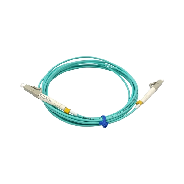
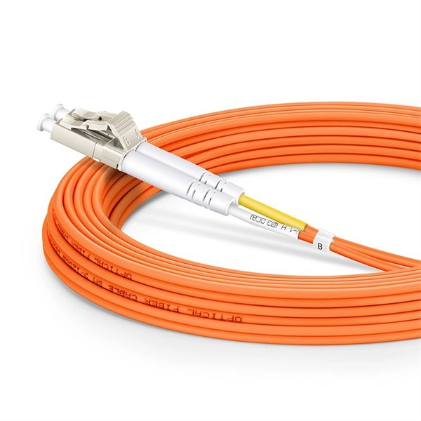
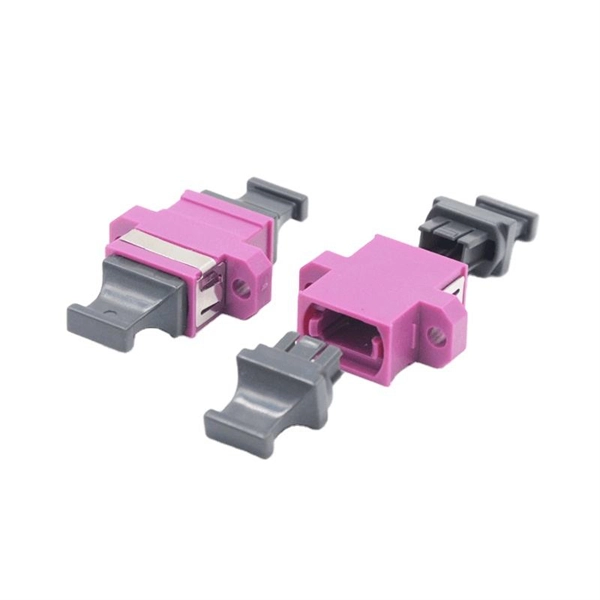
With a variety of kit options available, you can choose between the easy-to-use Quick Clean™ Cleaners, the convenient cleaning cube/card, and the best optic solvent pen to clean both patch cords and fiber.
[PDF]
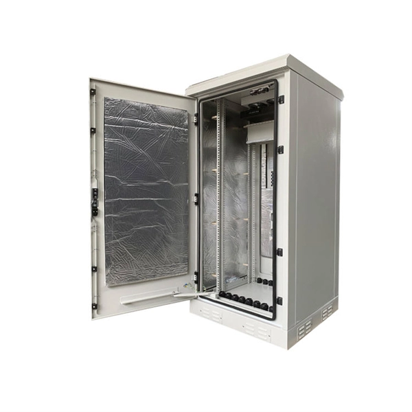
In this article, we'll explore the best practices for installing and maintaining fiber optic cables in data centers, ensuring optimal performance, reliability, and scalability for years to come. Master data center fiber optic implementation with detailed technical specifications, installation procedures, and optimization strategies. Explore advanced configurations, testing protocols, and industry best practices. Modern data centers represent the pinnacle of fiber optic technology. As data centers continue to grow in complexity and scale, efficient fiber optic cabling is essential for maintaining high performance, reliability, and scalability. You'll learn how to: Disorganized cabling creates direct financial consequences. Before a single cable is laid, thorough planning and design are crucial for a successful fiber optic. The Fiber Optic Association, Inc. (FOA) was founded in 1995 to help develop the workforce to build the fiber optic networks to support a rapid expansion in communications and the Internet. The charter of the FOA was to promote professionalism in fiber optics through education, certification, and.
[PDF]
The generally accepted and code-compliant height for switches is typically 48 inches (4 feet) from the finished floor to the top of the switch box. This standard helps ensure accessibility and consistency across installations. While the National Electrical Code (NEC) doesn't specify a mandatory standard outlet height for most general-use receptacles, established industry best practices and accessibility laws provide clear guidance. The NEC (Article 210. 52) specifies where receptacles must be placed (spacing along walls, required. The commercial electrical code requires switches at 42 to 48 inches and receptacles at 18 inches above finished floor in most applications. This height is an ergonomic choice, aligning well with the average reach.
[PDF]
The corrosion resistance of the cable trays is based on the UNE-EN IEC 61537 standard and is verified by the continuous salt spray test (ISO 9227). Both procedures are certified and audited by AENOR, which guarantees full compliance with national and international standards. This guide provides detailed insights into preventing corrosion and extending the lifespan of cable trays. Corrosion can weaken cable trays, leading to failures that disrupt operations and pose safety risks. This treatment is ideal for environments requiring: Selecting the right Cable Trays Surface Treatment depends on several factors: Environmental Conditions: Evaluate exposure to moisture, chemicals, UV, or extreme temperatures. Budget Constraints: Balance performance requirements with cost. This white paper compares the High Resistance (HR) and Hot-Dip Galvanising (HDG) solutions and highlights the new High Resistance range, ZnAl wiremesh, ZnMg metal cable trays and accessories and ZnNi screws and bolts. Presentation pictures do not always include Personal Protective Equipment (PPE). association representing the major electrical equipment manufac-turers in the U. The protection classes. Cable trays are often exposed to: Without proper protection, corrosion can lead to: A corroded cable tray is not just a maintenance issue — it is a safety risk. Choosing the right finish depends on the installation environment. The most commonly used options are: GI trays are made from.
[PDF]
Its entrance shall be from the ground floor level and its height shall not be more than 2. Scope Definitions General requirements for electrical installations Customer service point Excess current protection Earthing and earth leakage protection Wiring and distribution arrangements 700 Wires and cables 701 Flexible cords and cables 702 Joints, connections and terminations 703 Bunching. The EWA has adopted many of the clauses from the latest editions of the IEC, IEE & KUWAIT Regulations, modifying them to suit Bahrain conditions where necessary. It is the intention of the EWA to re- examine these Regulations periodically and to issue amendment sheets whenever it is considered. EWA's Standards and Regulations outlines essential guidelines and requirements to ensure the safe, sustainable, and efficient management of resources and services. The first version of the Unified Guidebook of Building Permit Regulations was issued to cover the prerequisites and. For any complaints or comments regarding published and unpublished decisions and regulations in the Unified Building Code, please contact us at the following numbers:. This document presents a revised edition of the Regulations for Electrical Installations, superseding the 1985 version. Updated according to international standards while considering the local context in Bahrain, it establishes guidelines for electrical installations, including coordination between.
[PDF]
This article explains eight of the most important global fiber and cable standards — ITU-T, IEC, TIA, ISO/IEC, and Telcordia — covering their scope, applications, and why they matter in real-world deployments. Fiber optic network design refers to the specialized processes leading to a successful installation and operation of a fiber optic network. It includes determining the type of communication system(s) which will be carried over the network, the geographic layout (premises, campus, outside plant. Our expert OSP Network Designers in FTTH, FTTx designs and standards enables us to provide top quality services to EPC companies all over the world. For New Network builds, we have experience ranging from Single and Multi-dwelling Units, Commercial Units FTTH Fibre-to-the-Home networks, Outside. Fiber optic networks are built on well-defined standards that ensure quality, performance, and interoperability. 8 billion in 2022 and is expected to reach $11. This is the dominant broadband access technology across half of OECD countries today. Source: OECD broadband.
[PDF]