This step-by-step guide aims to provide a comprehensive understanding of the techniques and considerations involved in successfully connecting optical fibers, offering invaluable insights for professionals and enthusiasts in the field. In high-speed data networks, the seamless integration of fiber optic cables with SFP (Small Form-Factor Pluggable) modules is critical for reliable signal transmission. SFP transceivers bridge electrical and optical signals, making them indispensable in data centers, telecom networks, and. Proper connection of fiber optic cables is essential to harness these benefits fully, as even minor errors can lead to significant performance issues like signal loss. This article will guide you through the necessary tools, materials, and methods on how to connect fiber optic cables effectively. This section describes how to install optical transceivers on the SFP or SFP+ ports and connect them to the ports of the peer device using optical fibers according to the network plan. The USG supports both 1 Gbit/s, 10 Gbit/s, and 40 Gbit/s optical modules. The optical modules at both ends are. There are many types of fiber optic connectors, including SC, LC, FC, ST, D4, MU, MT/MPO, etc. These connectors can be divided into single-mode and multi-mode fiber optic connectors according to their structure and purpose. In this tutorial.
[PDF]
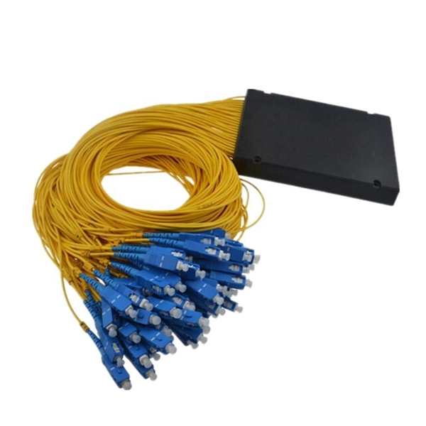
The most common operating principle of a directional fiber coupler is evanescent wave coupling in a configuration where two fiber cores come close to each other. Such a device can be made by heating two bare fibers such that the glass begins to melt and the fibers fuse together. The tutorial has the following parts: Figure 1: A 2-by-2 fiber coupler. When using fiber optics, one often needs to use fiber. Fiber optic couplers, also known as fiber optic splitters, are devices used to split or combine optical signals in fiber optic networks. They play a crucial role in various applications, such as telecommunications, data centers, and fiber-to-the-home (FTTH) installations. In simple terms, they serve as the 'traffic managers' of the light that carries information within the fiber optic network. It functions by dividing a single incoming light path into multiple outgoing paths, or by combining light from several input paths into a single output fiber. This capability is fundamental. This tab provides a brief explanation of how we determine several key specifications for our 1x2 couplers. 1x2 couplers are manufactured using the same process as our 2x2 fiber optic couplers, except the second input port is internally terminated using a proprietary method that minimizes back.
[PDF]
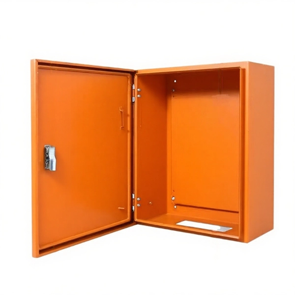
Open Frame Rack: A rack structure without doors or side panels, allowing easy access and better airflow. A data center server rack is the physical foundation of modern IT infrastructure, enabling the organized installation of servers, switches, PDUs, UPS systems, and structured cabling. There are three primary rack types - open-frame racks, enclosed cabinets, and wall-mount racks, each suited for. Understanding data center racks, chassis, and their differences is crucial for efficient server deployment. This guide clarifies common terminology confusion and design implications. Modern data center racks house multiple server chassis in standardized dimensions, enabling efficient space. IT racks are the backbone of any data center, housing critical infrastructure like servers, networking equipment, and storage devices. Whether you are designing a new setup or optimizing an existing one, understanding key IT rack terminologies is essential. This article provides an overview of the. A server rack, also known as a server cabinet, is a specialized metal frame structure designed to store and organize IT equipment. It supports hardware, enhances cooling, and ensures efficient power distribution. This guide covers everything you need for. Recommended (Suitable for all four classes; explore data center metrics in this paper for conditions outside this range. Classes A3, A4, B, and C are.
[PDF]